basale Eve Plus Wall Base 24v
Instruction Manual

Safety instructions
Before installing the unit, read this manual thoroughly and retain it for future reference. The device should be installed in compliance with official regulations valid in the country of use. The device may only be installed and connected by qualified electricians. Ensure that electricity is switched off when installing or unmounting the device. Do not open, dismantle, alter or modify the device.
Components
Wall base0130-01Eve Plus Cover(not included)
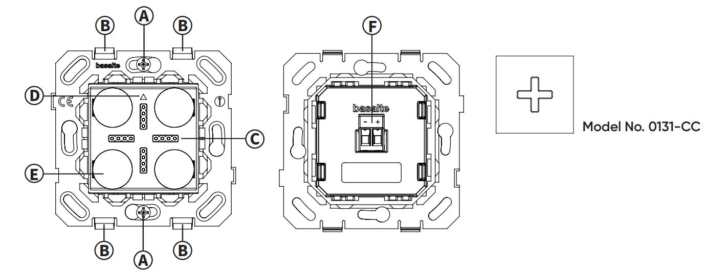
A Opening to fix the outlet to the wall boxB Clips to mount the cover plateC Charging connector for Eve Plus sleeveD This sign upE Aligning magnetsF 24V DC power connector
Wall boxes
The wall base should be installed in European wall boxes with screws. The distance between the screws needs to be 60mm, and a minimum depth of 45 mm is required. Square wall boxes size 60 x 60 mm are compatible with the sockets. Round wall boxes should have an inner diameter of 64mm or more.The following round wall boxes are compatible with the Basalte sockets:
- Helia round with cut hole 68 mm (type 247, 261).
- Kaiser round with cut hole 68 mm (type 9063-xx, 9064-xx, 9062-xx).
- Legrand beatbox round (ref 080051, 080061, 080052, 080053).
- ABB round Hafobox MD4050 and hollow wall boxes HW-50, HW50-G, HW52-F (Except HW52-F IGD and HW52-F BW).
![]() When using other round boxes, please verify the compatibility upfront.
When using other round boxes, please verify the compatibility upfront.
Do not use the following wall boxes:
- Helia O-range
- Kaiser (1055-xx 1056-xx)
- ABB 3040
- ABB HW52-F IGD and HW52-F BW
Installation instructions
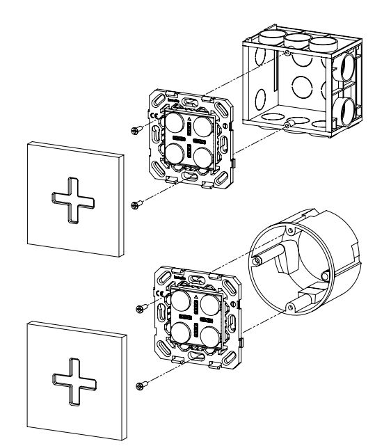
- Install square wall box (60mm) or compatible round wall box. The wall box should have screws with a vertical distance of 60mm and a minimum depth of 45mm.
- Connect the 24V DC power lines using the terminals.
- Fix the wall base to the wall box with 2 screws using the holes on the vertical axis.
- Mount the cover using the clips (see drawing below).
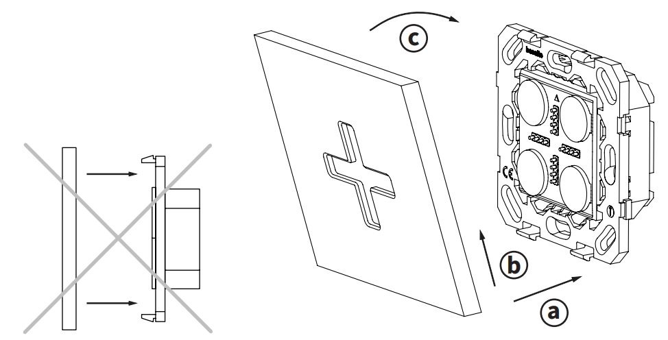
A Place the frame over the lower clipsB Push the frame upwards and tilt towards the wallC Attach the frame over the top clips
![]() Pushing the frame straight into the clips without pushing upwards and lifting, might damage the wall base.
Pushing the frame straight into the clips without pushing upwards and lifting, might damage the wall base.
Cabling
The cable between the DC power supply and wall base must have a cable section of at least 0.8mm2 and a maximum of 1.5mm2. The applicable maximum cable lengths are specified both 12V and 24V. To limit power loss in the cable, we recommend using star wiring from the power supply to each single wall base. We advise automatically put the iPad in standby mode when not in use to reduce power consumption.
Maximum cable length between DC power supply and wall base
Cable type0.8mm2 (AWG 19)1.0mm2 (AWG 18)1.5mm2 (AWG 17)
12V DC50m (164ft)60m (197ft)90m (295ft)
24V DC300m (984ft)400m (1312ft)500m (1640ft)
How to remove the Socket front cover
(see drawing below)
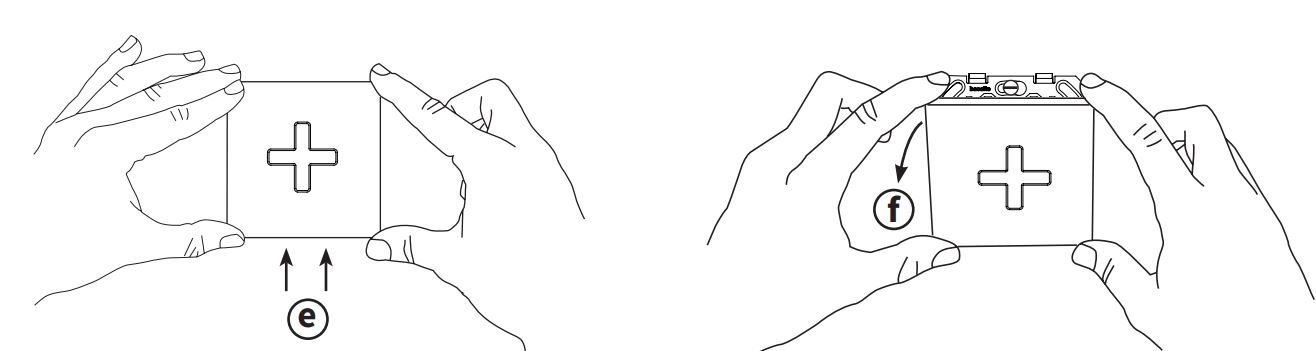 E Push the frame upwardsF Tilt the frame away from the wall
Technical data
Power supply: 10 – 30 V DCConsumption: Input power 15WOperating temperature: 0°C – +35°C
basalte bv | hundelgemsesteenweg 1A | 9820 merelbeke | belgium t +32 (0)9 385 78 38 | f +32 (0)9 329 66 95 | www.basalte.be | [email protected] ![]()
References
[xyz-ips snippet=”download-snippet”]