BEHA AMPROBE ®
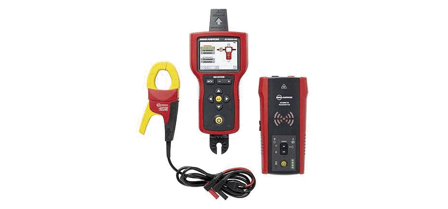
AT-8000-EUR Advanced Wire TracerUser Guide

Reliable, precise breaker/fuse identification Tested by Fluke and safety certified by 3rd party labs
Intuitive Transmitterautomatically senses whether the system is energized or de-energizedMost accurate wire tracing in its class with 10 sensitivity modes.
Tracing Energized Wires – Smart SensorTM
1. Set-up: Test Leads

- Plug the green and red test leads into the Transmitter.
- Connect the green wire to a separate neutral.
- Connect the red test lead to the wire being traced, For receptacles, make sure to connect the test lead to the line/phase wire. For Energized systems the signal will ONLY be transmitted between the load-side to which the Transmitter is connected and the source of power.
2. Set-up: Transmitter
![]()
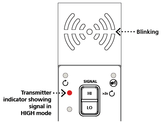
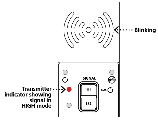
- Turn on the Transmitter.
- Verify that the test leads are properly connected; the red LED voltage status light should be on for circuits with voltage above 30 V AC/DC.
- Select HIGH signal mode by pressing HI.
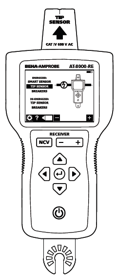
Receiver:
Energized Smart SensorTM Mode
The Smart SensorTM enables easier wire tracing by showing the direction and position of the wire and is the recommended method for tracing Energized wires.
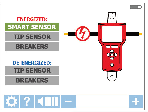
- Turn on the Receiver and select SMART SENSORTM mode using the directional arrows.
- Hold the Receiver with the Smart SensorTM facing the target area.
- Move the Receiver in direction indicated by the arrow on the screen. If the screen flashes a “?”in a red target then either no signal is detected or the signal is not adequate enough to display direction; increase the sensitivity using the “+” button on the Receiver.
- Press ENTER when complete to return to the home screen.

TIP: For best results, keep the Receiver at least 1 m (3 feet) from the Transmitter and its test leads to minimize signal interference and improve wire tracing results. Select the “Long” Smart Sensor TM Range in the Settings Menu if working with wires that are greater than 1 m (3 feet) deep.
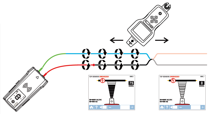
Tracing Energized and De-energized Wires – Tip Sensor
1. Set-up: Test Leads

- Plug the green and red test leads into the Transmitter.
- Connect the green wire to a separate neutral.
- Connect the red test lead to the wire being traced, For receptacles, make sure to connect the test lead to the line/phase wire. For Energized systems the signal will ONLY be transmitted between the load-side to which the Transmitter is connected and the source of power
2. Set-up: Transmitter
- Turn on the Transmitter.
- Verify that the test leads are properly connected; the red LED voltage status light should be on for circuits with voltage above 30 V AC/DC, and it should be off for De-energized circuits below 30 V AC/DC.
- Select HIGH signal mode by pressing HI.
Receiver:
Energized and De-energized Tip Sensor Modes
Use this mode for pinpointing a wire in a bundle or tracing in corners and confined spaces such as junction boxes and inside enclosures.
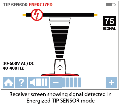
- Turn on the Receiver and select either Energized or De-energized TIP SENSOR mode using the directional arrows.
- Hold the Receiver with the Tip Sensor facing the target area.
- Scan the target area with the Tip Sensor to find the highest signal level, then begin tracing the detected wire. Increase or decrease sensitivity of the Receiver by pressing + or – on the keypad as necessary.
- Press ENTER when complete to return to the home screen.
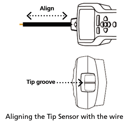
TIP: In Energized mode, align the groove on the Tip Sensor with the wire direction for best results; the signal may not be detected without this alignment. De-energized mode uses a different antenna in the Tip Sensor than Energized mode. Specific alignment of the Tip Sensor groove to the wire is not required. De-energized wire tracing results are based only on how close the Tip Sensor is to the wire.
Connecting Transmitter to an Energized Working System
![]()
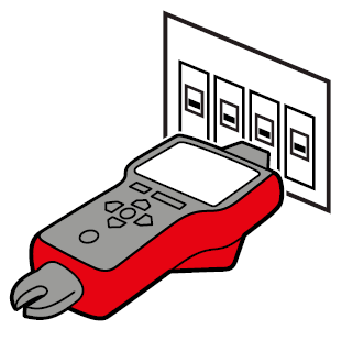
The Transmitter, with the red test lead, can be directly connected to the live wire of the working electrical equipment under load (motor, electronics, etc). Tracing can be performed without needing to turn off the equipment or switching power off.
Identifying Energized and De-energized Breakers and Fuses
1. Set-up: Test Leads

- Plug the green and red test leads into the Transmitter.
- Connect the green wire to a separate neutral.
- Connect the red test lead to the wire being traced, For receptacles, make sure to connect the test lead to the line/phase wire. For Energized systems the signal will ONLY be transmitted between the load-side to which the Transmitter is connected and the source of power.
Note: Simplified direct connection can also be used to connect the Transmitter (refer to the user manual for further instructions).
2. Set-up: Transmitter
- Turn on the Transmitter.
- Verify that the test leads are properly connected; the red LED voltage status light should be on for circuits with voltage above 30 V AC/DC, and it should be off for De-energized circuits below 30 V AC/DC.
- Select HIGH signal mode by pressing HI.
Identifying Energized and De-energized Breakers and Fuses
Receiver:
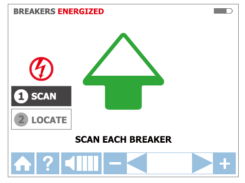
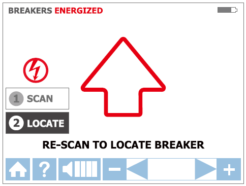
BREAKERS Mode
Tracing breakers/fuses is a two-step process:
- SCAN – Scan each breaker/fuse for one second. The Receiver will record tracing signal levels.
- LOCATE – The Receiver will indicate the single breaker/fuse with the strongest recorded signal.
Correct alignment of the Tip Sensor to the breaker/fuse
Step 1 – 1 SCAN
- Turn on the Receiver and select either Energized BREAKERS mode or De-Energized BREAKERS mode using the directional arrows.
- Align the groove on the Tip Sensor with the breaker/fuse lengthwise.
- Scan each breaker/fuse by touching it with the Tip Sensor. To assure sufficient time between the scans, wait for active green arrow and audible alert before moving to the next breaker/fuse. The order of scanning does not matter. You can scan breakers/fuses multiple times. The Receiver records the highest detected signal.
Step 2 – 2 LOCATE
- Select LOCATE mode by using the directional arrows.
- Rescan each breaker by touching each with the Tip Sensor for one second. Active red arrow indicates scanning process. Scan all breakers until solid green arrow and audible alert (continuous beep) indicates that the correct breaker was found.
- Press ENTER when complete to return to the home screen.

Receiver: NCV Mode
The NCV (Non-Contact Voltage) mode is used to verify that a wire is Energized. This method does not require the use of the Transmitter. The Receiver will detect an Energized cable if the voltage is between 90 V and 600 V AC and between 40 Hz and 400 Hz. No current flow is necessary.
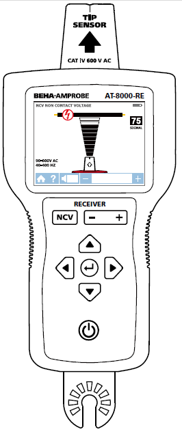
1. Turn on the Receiver and press the NCV button.
2. Hold the Receiver with the Tip Sensor facing the target area.
3. Scan the target area with the Tip Sensor to find the highest signal level, then begin tracing the detected wire. For precise pinpointing of line/phase wire versus neutral wire, increase or decrease sensitivity by pressing + or – on the keypad.
4. Press ENTER when complete to return to the home screen.Note: For safety, before working with wires, always verify that they are De-energized with an additional voltage tester.
Finding Breaks and Opens
1. Set-up: Transmitter

- Turn on the Transmitter.
- bthat the test leads are properly connected; the red LED voltage status light should be off for De-energized circuits below 30 V AC/DC.
- Select HIGH signal mode by pressing HI.
2. Set-up: Receiver
1. Turn on the Receiver and perform tracing in De-energized TIP SENSOR mode

Tracing a cable to find breaks or opens
- Start tracing the cable until the signal stops.
- Verify the place of the fault: move the Transmitter to the other end of the wire and repeat tracing from the opposite end. If the signal stops at the exact same location the fault has been located.
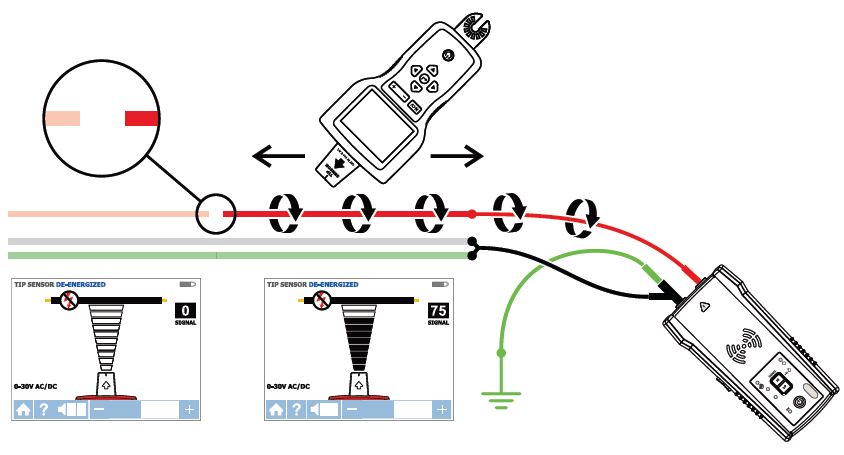
Note: For best results, ground all De-energized wires that run in parallel with the black test lead.
Finding Shorts
1. Set-up: Transmitter

- Turn on the Transmitter.
- Verify that the test leads are properly connected; the red LED voltage status light should be off for De-energized circuits below 30 V AC/DC.
- Turn the Transmitter to Loop mode by pressing HIGH button for two seconds. Verify that the Loop LED is ON.
2. Set-up: Receiver
- Turn on the Receiver and perform tracing in Energized TIP SENSOR mod
Tracing a cable to find shorts
- Start tracing the cable until the signal stops.
- Verify the place of the fault: move the Transmitter to the other end of the wire and repeat tracing from the opposite end. If the signal stops at the exact same location the fault has been located.
Note: This method will be affected by signal cancellation effect. Expect a relatively weak signal.
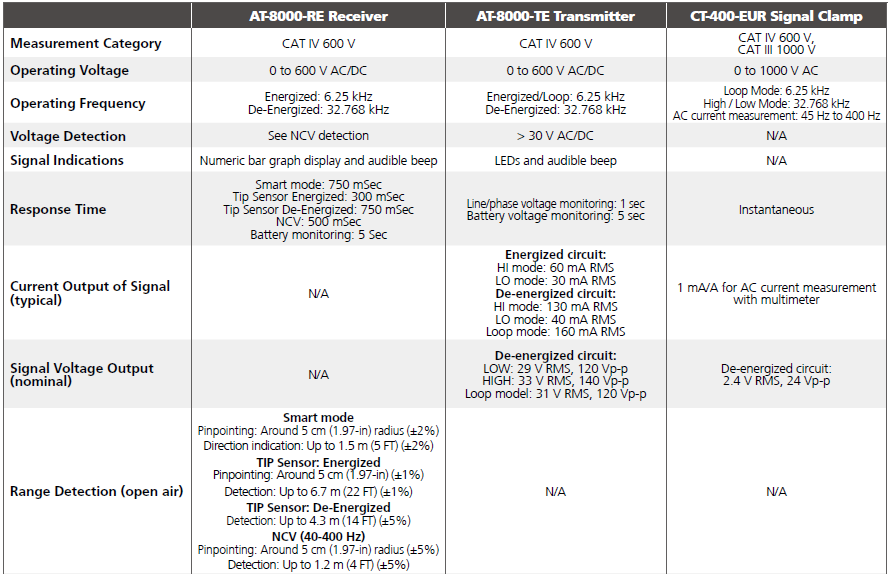
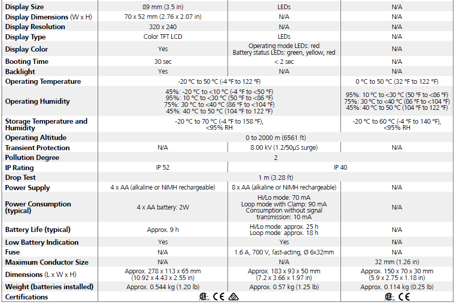
Specifications
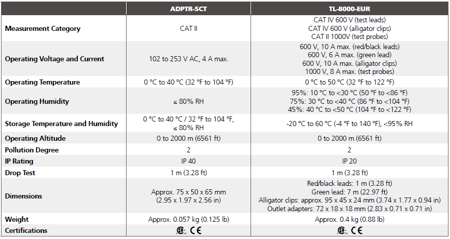
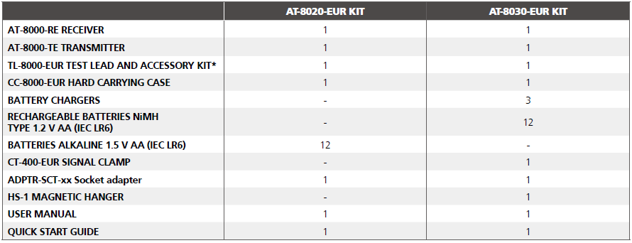
Accessory Specifications
Included in Wire Tracer Kits
*TL-8000-EUR test lead and accessory kit includes:
- 2 x 1 m test leads (red, black): CAT IV 600 V
- 1 x 7 m test lead (green): CAT IV 600 V
- 2 x Alligator clips (red, black): CAT IV 600 V
- 2 x Outlet blade adapters (red, black): CAT II 300 V
- 2 x Outlet round adapters (red, black): CAT II 300 V
Optional accessories:
HS-1 Magnetic hangerTL-8000-25M Test leadCT-400-EUR Signal clamp
Beha-Amprobe©
Division of Fluke Corp. (USA)c/o Fluke Europe BV
In den Engematten 1479286 Glottertal, GermanyTel. +49 (0) 7684 – 8009-0beha-amprobe.de
Science Park Eindhoven5110 NL-5692 EC SonThe NetherlandsTel. +31 (0) 40 267 51 00beha-amprobe.com
52 Hurricane WayNR6 6 JB United KingdomE-mail: beha-amprobe.com
References
[xyz-ips snippet=”download-snippet”]