behringer 110 VCO/VCF/VCA Legendary Analog VCO/VCF/VCA Module for Eurorack User Guide
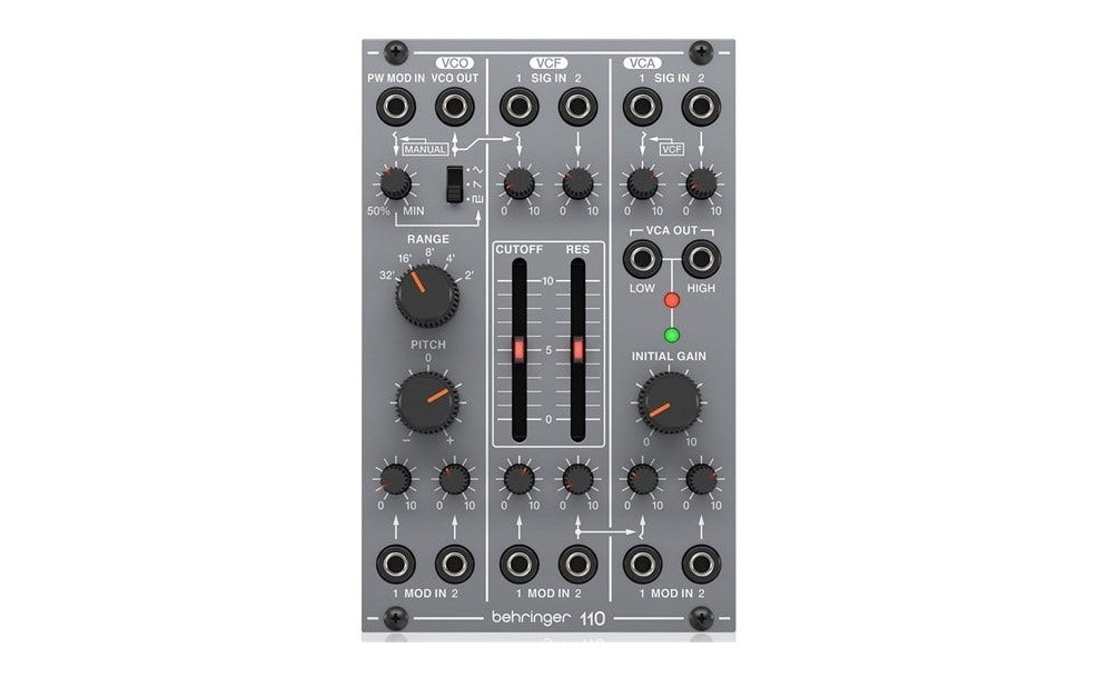
110 VCO/VCF/VCA Controls
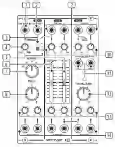
- PW MOD – Accepts a voltage from another module to control the pulse width. When a jack is inserted the MOD MANUAL control acts as a MOD input level control.
- VCO OUT – Send the VCO signal to another source via 3.5 mm TS cable.
- WAVEFORM – Select triangle, sawtooth or pulse waveforms for the VCO.
- MOD MANUAL – Sets the ratio between the upper and lower portions of the pulse wave.
- RES – Boosts the resonance frequencies selected with the CUTOFF FREQ slider, potentially causing VCF oscillation.
- CUTOFF FREQ – Adjusts the cutoff frequency of the low-pass filter.
- RANGE – Sets the pitch range of the VCO in octave steps.
- PITCH – Fine tunes the pitch.
- VCF/VCA SIG IN – Connect incoming signals via 3.5 mm TS cables.
- SIG LEVEL – Adjust the level of the signals connected to the inputs.
- VCA OUT – Sends the VCA signal via 3.5 mm TS cable with either high or low signal levels.
- INITIAL GAIN – Adjusts the initial gain level when there is no control voltage present. The adjacent LEDs will light to indicate signal (green) and overload (red).
- MOD LEVEL – Adjusts the level of the signal connected to the associated MOD IN jack.
- MOD IN – Accepts voltages that control or modulate the VCO, VCF or VCA
Power Connection
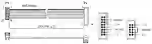
The module comes with the required power cable for connecting to a standard Eurorack power supply system. Follow these steps to connect power to the module. It is easier to make these connections before the module has been mounted into a rack case.
- Turn the power supply or rack case power off and disconnect the power cable.
- Insert the 16-pin connector on the power cable into the socket on the power supply or rack case. The connector has a tab that will align with the gap in the socket, so it cannot be inserted incorrectly. If the power supply does not have a keyed socket, be sure to orient pin 1 (-12 V) with the red stripe on the cable.
- Insert the 10-pin connector into the socket on the back of the module. The connector has a tab that will align with the socket for correct orientation.
- After both ends of the power cable have been securely attached, you may mount the module in a case and turn on the power supply
Installation
The necessary screws are included with the module for mounting in a Eurorack case. Connect the power cable before mounting.
Depending on the rack case, there may be a series of fixed holes spaced 2 HP apart along the length of the case, or a track that allows individual threaded plates to slide along the length of the case. The free-moving threaded plates allow precise positioning of the module, but each plate should be positioned in the approximate relation to the mounting holes in your module before attaching the screws.
Hold the module against the Eurorack rails so that each of the mounting holes are aligned with a threaded rail or threaded plate. Attach the screws part way to start, which will allow small adjustments to the positioning while you get them all aligned. After the final position has been established, tighten the screws down.
Specifications
| Inputs | |
| Pulse width mod | |
| Type | 3.5 mm TS jack, DC coupled |
| Impedance | >70 kΩ, unbalanced |
| Maximum input level | 0 V to +10 V, 4% per volt |
| Signal input | |
| Type | 4 x 3.5 mm TS jacks, AC coupled |
| Impedance | >50 kΩ, unbalanced |
| Max input level | +17 dBu @ unity gain |
| VCO mod input | |
| Type | 2 x 3.5 mm TS jacks, summed |
| Impedance | >50 kΩ, unbalanced |
| CV range | 0 V to +10 V, 1 V/oct |
| VCF mod input | |
| Type | 2 x 3.5 mm TS jacks, summed |
| Impedance | >50 kΩ, unbalanced |
| CV range | 0 V to +10 V, 1 V/oct |
| VCA mod input | |
| Type | 2 x 3.5 mm TS jacks,summed |
| Impedance | >50 kΩ, unbalanced |
| CV range | 0 V to +10 V, typically 1 V per 10 dB |
LEGAL DISCLAIMER
Music Tribe accepts no liability for any loss which may be suffered by any person who relies either wholly or in part upon any description, photograph, or statement contained herein. Technical specifications, appearances and other information are subject to change without notice. All trademarks are the property of their respective owners. Midas, Klark Teknik, Lab Gruppen, Lake, Tannoy, Turbo sound, TC Electronic, TC Helicon, Be hringer, Bugera, Oberheim, Auratone, Aston Microphones, Aston Microphones and Cool audio are trademarks or registered trademarks of Music Tribe Global Brands Ltd. © Music Tribe Global Brands Ltd. 2021 All rights reserved.
LIMITED WARRANTY
For the applicable warranty terms and conditions and additional information regarding Music Tribe’s Limited Warranty, please see complete details online at musictribe.com/warranty.
 Hereby, Music Tribe declares that this product is in compliance with Directive 2014/30/EU, Directive 2011/65/EU and Amendment 2015/863/EU, Directive 2012/19/ EU, Regulation 519/2012 REACH SVHC and Directive 1907/2006/EC.
Full text of EU DoC is available at https://community.musictribe.com/
EU Representative: Music Tribe Brands DK A/SAddress: Ib Spang Olsens Gade 17, DK – 8200 Aarhus N, Denmark

[xyz-ips snippet=”download-snippet”]