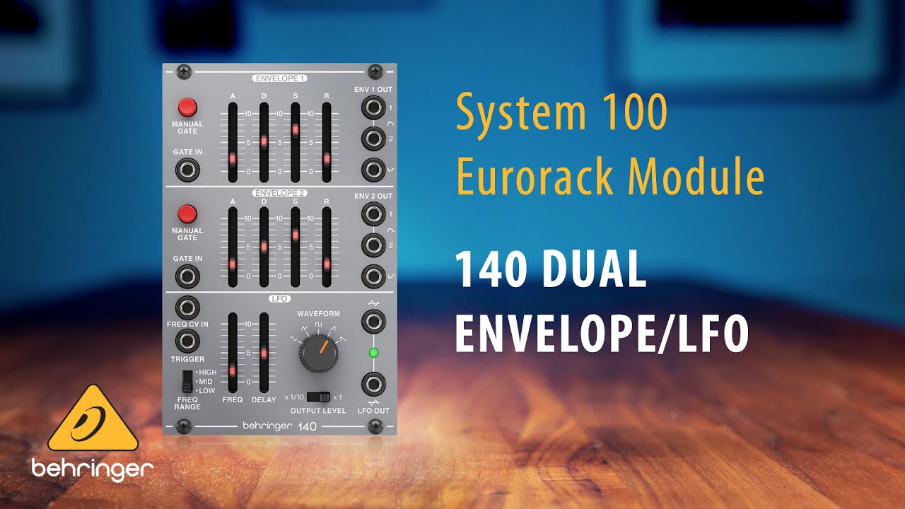
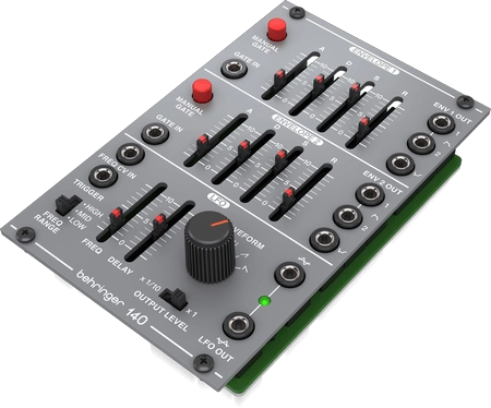
behringer 140 DUAL ENVELOPE/ LFO Legendary Analog Dual Envelope/LFO Module for Eurorack
LEGAL DISCLAIMER
Music Tribe accepts no liability for any loss which may be suffered by any person who relies either wholly or in part upon any description, photograph, or statement contained herein. Technical specifications, appearances and other information are subject to change without notice. All trademarks are the property of their respective owners. Midas, Klark Teknik, Lab Gruppen, Lake, Tannoy, Turbosound, TC Electronic, TC Helicon, Behringer, Bugera, Oberheim, Auratone, Aston Microphones, Aston Microphones and Coolaudio are trademarks or registered trademarks of Music Tribe Global Brands Ltd. © Music Tribe Global Brands Ltd. 2021 All rights reserved.
LIMITED WARRANTY
For the applicable warranty terms and conditions and additional information regarding Music Tribe’s Limited Warranty, please see complete details online at musictribe.com/warranty
140 DUAL ENVELOPE/ LFO Controls

- MANUAL GATE – Press and hold to start the envelope cycle.
- EXT GATE – Connect a gate signal to control the envelope cycle.
- ATTACK TIME – Adjusts the rate at which the envelope reaches its peak voltage.
- DECAY TIME – Adjusts the rate at which the envelope decays from its peak level to its designated sustain level.
- SUSTAIN LEVEL – Controls the level at which the envelope remains after its peak but before release, sustaining as long as the input signal is present or the manual gate switch is held down.
- RELEASE TIME – Controls how quickly the envelope falls after the input signal stops or the manual gate switch is released.
- ENV OUTPUTS – Send up to 2 positive waveforms and a negative waveform to other modules via these output connectors.
- FREQ RANGE – Sets the oscillating frequency range of the LFO in 3 steps.
- FREQ – Manually sets the oscillating frequency of the LFO.
- DELAY – Sets the time from when a trigger signal is received until the LFO begins operating again.
- FREQ CV IN – Accepts voltage for controlling the LFO frequency with an external source.
- TRIGGER – Connect a trigger signal to turn the LFO off until the end of the trigger cycle.This works along with the Delay slider, and the LFO recovery takes about 20 seconds. The rear panel features a jumper that can be removed if you don’t want the LFO to be re-triggered.
- OUTPUT LEVEL – Selects between standard or 1/10th output level for the LFO OUT jacks.
- WAVEFORM – Select between sine, triangle, pulse, sawtooth or reverse sawtooth for the LFO waveform output.
- LFO OUT – Sends the LFO output to other modules. The upper jack is non-inverting and the lower jacks is inverting.
Power Connection
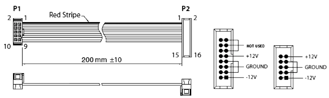
The 140 comes with the required power cable for connecting to a standard Eurorack power supply system. Follow these steps to connect power to the module. It is easier to make these connections before the module has been mounted into a rack case.
- Turn the power supply or rack case power off and disconnect the power cable.
- Insert the 16-pin connector on the power cable into the socket on the power supply or rack case.The connector has a tab that will align with the gap in the socket, so it cannot be inserted incorrectly.If the power supply does not have a keyed socket, be sure to orient pin 1 (-12 V) with the red stripe on the cable.
- Insert the 10-pin connector into the socket on the back of the module. The connector has a tab that will align with the socket for correct orientation.
- After both ends of the power cable have been securely attached, you may mount the module in a case and turn on the power supply.
Installation
The necessary screws are included with the module for mounting in a Eurorack case. Connect the power cable before mounting.Depending on the rack case, there may be a series of fixed holes spaced 2 HP apart along the length of the case, or a track that allows individual threaded plates to slide along the length of the case. The free-moving threaded plates allow precise positioning of the module, but each plate should be positioned in the approximate relation to the mounting holes in your module before attaching the screws.Hold the module against the Eurorack rails so that each of the mounting holes are aligned with a threaded rail or threaded plate. Attach the screws part way to start, which will allow small adjustments to the positioning while you get them all aligned. After the final position has been established, tighten the screws down.
Specifications
Input
| Ext gate | 3.5 mm jack, DC coupled |
| Impedance | 50 kΩ |
| Min input level | +3 V |
| Max input level | +10 V |
| Frequency CV input | 3.5 mm jack, DC coupled |
| Impedance | 100 kΩ |
| Max input level | +/-10 V |
| CV scaling | 1 V / octave |
| Ext LFO trigger | 3.5 mm jack, DC coupled |
| Impedance | 50 kΩ |
| Max input level | +10 V |
Output
| Envelope 1/2 out | 3.5 mm jack, DC coupled |
| Impedance | 1 kΩ |
| Max output level | +/-10 V |
| LFO output | 3.5 mm jack, DC coupled |
| Impedance | 1 kΩ |
| Max output level | 10 V pk-pk |
Controls
| Attack | 1.5 ms – 7.5 s |
| Decay | 4 ms – 15 s |
| Sustain | +/-10 V |
| Release | 4 ms – 15 s |
| Manual gate switch | Envelope cycle start |
| Frequency range switch | LFO low 0.05 – 1.8 Hz, |
| mid 0.2 – 9 Hz, | |
| high 0.5 – 30 Hz | |
| Frequency | LFO frequency, |
| 0.05 Hz – 30 Hz | |
| Delay | LFO operation delay, 0 – 7 s |
| Waveform rotary switch | Sine, triangle, pulse, sawtooth, rev sawtooth |
| Output level switch | 1 V pk-pk, 10 V pk-pk |
Hereby, Music Tribe declares that this product is in compliance with Directive2014/30/EU, Directive 2011/65/EU and Amendment 2015/863/EU, Directive 2012/19/ EU, Regulation 519/2012 REACH SVHC and Directive 1907/2006/EC.Full text of EU DoC is available at https://community.musictribe.com/EU Representative: Music Tribe Brands DK A/SAddress: Ib Spang Olsens Gade 17, DK – 8200 Aarhus N, Denmark
![]()
[xyz-ips snippet=”download-snippet”]