![]() Quick Start Guide150 RING MOD/NOISE/ S&H/LFOV 1.0
Quick Start Guide150 RING MOD/NOISE/ S&H/LFOV 1.0
Controls
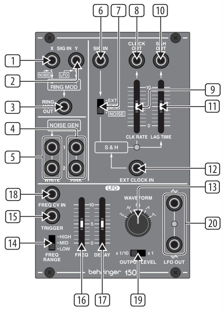
- EXT SIG X/NOISE jack routes audio signals or noise into the ring modulator. The audio signal or noise coming in throughthe EXT SIG X/NOISE jack is combined with and modulated by the carrier signal routed into the EXT SIG Y/LFO jack.
- EXT SIG Y/LFO jack routes the carrier signal into the ring modulator. The carrier signal can be in the audio range, such as a 500 Hz sine wave, or a signal from Low-Frequency Oscillator (LFO).
- R.M OUT jack sends out the final ring modulator signal.
- PINK output jacks offer dual white pink noise outputs for use in other modules.
- WHITE output jacks offer dual white noise outputs for use with other modules
- EXT SIG input jack routes external signals into the S&H circuit for processing. Use the EXT/LFO/NOISE switch to optimize the EXT SIG input for different types of signals.
- EXT/LFO/NOISE sliding switch optimizes the EXT SIG for use with control signals (EXT), signals from a Low-Frequency Oscillator (LFO), or noise signals (NOISE).
- CLOCK OUT jack sends out a clock signal generated inside the S&H circuit.
- CLOCK RATE slider controls the internal clock signal’s rate before the clock signal is routed out through the CLOCK OUT jack.
- S&H OUT jack sends out the final S&H (Sample & Hold) signal over cables with 3.5 mm TS connectors.
- LAG TIME slider can be used to smooth out the changes between control voltage values as the slider is raised, similar to a portamento or glide effect on a keyboard.
- EXT CLOCK IN input jack routes an external clock signal into the S&H circuit.
- WAVEFORM knob selects between sine, triangle, square, ramp, and sawtooth waveforms for the LFO.
- FREQ RANGE sliding switch selects between high (H), mid (M), and low (L) frequency ranges.
- TRIGGER jack allows a control voltage to trigger the LFO waveform by resetting the amplitude to 0. The waveform then returns to the original amplitude at a rate set by the DELAY slider.
- FREQ slider fine-adjusts the LFO frequency within the range chosen by the FREQ RANGE switch.
- DELAY slider controls the amount of time that elapses between the beginning of a new note and the LFO’s amplitude peak.
- FREQ CV IN input jack allows a control voltage to control the LFO frequency in place of the FREQ slider.
- OUTPUT LEVEL sliding switch selects between a full-strength LFO output signal (x1 setting) and a 1/10th-strength signal (x 1/10 setting).
- LFO OUT output jacks offer dual LFO outputs for use with cables with 3.5 mm TS connectors.
Power Connection
The 150 RING MOD/NOISE/S&H/LFO module comes with the required power cable for connecting to a standard Eurorack power supplysystem. Follow these steps to connect power to the module. It is easier to make these connections before the module has been mounted into a rack case.
- Turn the power supply or rack case power off and disconnect the power cable.
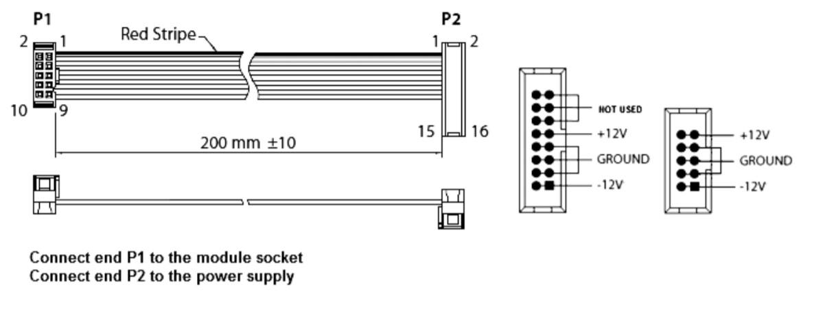
- Insert the 16-pin connector on the power cable into the socket on the power supply or rack case. The connector has a tab that will align with the gap in the socket, so it cannot be inserted incorrectly. If the power supply does not have a keyed socket, be sure to orient pin 1 (-12 V)with the red stripe on the cable.
- Insert the 10-pin connector into the socket on the back of the module. The connector has a tab that will align with the socket for correct orientation.
- After both ends of the power cable have been securely attached, you may mount the module in a case and turn on the power supply.
Installation
The necessary screws are included with the module for mounting in a Eurorack case. Connect the power cable before mounting.Depending on the rack case, there may be a series of fixed holes spaced 2 HP apart along the length of the case, or a track that allows individual threaded plates to slide along the length of the case.The free-moving threaded plates allow precise positioning of the module, but each plate should be positioned in approximate relation to the mounting holes in your module before attaching the screws.Hold the module against the Eurorack rails so that each of the mounting holes is aligned with a threaded rail or threaded plate. Attach the screws partway to start, which will allow small adjustments to the positioning while you get them all aligned. After the final position has been established, tighten the screws down.
Specifications
Signal Connections
Ring modulator
| Ext signal X /Y | 2 x 3.5 mm jack |
| X Impedance | 100 kO unbalanced |
| Y impedance | 100 kO unbalanced |
| Maximum level | +20 dBu |
| R.M out | 1 x 3.5 mm jack |
| Impedance | 100 0 unbalanced |
| Maximum level | +15 dBu |
Noise generator
| White | 2 x 3.5 mm jack |
| Impedance | 1 kO unbalanced |
| Output level | 0 dBu |
| Pink | 2 x 3.5 mm jack |
| Impedance | 1 k0 unbalanced |
| Output level | 0 dBu |
S & H
| Ext signal | 1 x 3.5 mm jack |
| Impedance | 100 kO unbalanced |
| Maximum level | + 17 dBu |
| Ext clock in | 1 x 3.5 mm jack |
| Impedance | 100 kO unbalanced |
| Threshold | > 1 V |
| Clock out | 1 x 3.5 mm jack |
| Impedance | 1 kO unbalanced |
| S&Hout | 1 x 3.5 mm jack |
| Impedance | 1 kO unbalanced |
LFO
| Freq CV in | 1 x 3.5 mm jack |
| Impedance | 100 kO unbalanced |
| CV input range | 0 V to +10 V |
| LFO out | 2 x 3.5 mm jack |
| Impedance | 1 kO unbalanced |
| Output level | 1 V p-p / 10 V p-p |
Controls
|
S & H |
|
| Clock rate | 1 x slider, 2 Hz – 25 Hz |
| Lag time | 1 x slider, 0 – 8 seconds |
| Ext / LFO / noise | 3-way sliding switch |
|
LFO |
|
| Freq range | 3-way sliding switch High / mid / low, selectable |
| Frequency | 1 x slider, 0.03 Hz – 30 Hz in 3 ranges |
| Delay | 1 x slider, 4 ms to 8 seconds |
| Waveform | 5-way switch sine/triangle/ square / sawtooth /inverted sawtooth, selectable |
| Output level | 2-way sliding switch x3/40/ x1, selectable |
|
Power |
|
| Power supply | Eurorack |
| Current draw | 60 mA (+12 V), 50 mA (-12 V) |
|
Physical |
|
| Dimensions (H x W x D) | 44 x 81 x 129 mm (1.7 x 3.2 x5.1″) |
| Rack units | 16 HP |
| Weight | 0.16 kg (0.35 Ibs) |
LEGAL DISCLAIMER
Music Tribe accepts no liability for any loss which may be suffered by any person who relies either wholly on or in part upon any description, photograph, or statement contained herein. Technical specifications, appearances, and other information are subject to change without notice. All trademarks are the property of their respective owners.Midas, Klark Teknik, Lab Gruppen, Lake, Tannoy, Turbosound, TC Electronic, TC Helicon, Behringer, Bugera, Oberheim, Auratone, Aston Microphones and Coolaudio are trademarks or registered trademarks of Music Tribe Global Brands Ltd.© Music Tribe Global Brands Ltd. 2021 All rights reserved.
LIMITED WARRANTY
For the applicable warranty terms and conditions and additional information regarding Music Tribe’s Limited Warranty, please see complete details online at musictribe.com/warranty.
 Hereby, Music Tribe declares that this product is in compliance with Directive 2014/30/EU, Directive 2011/65/EUand Amendment 2015/863/EU, Directive 2012/19/EU, Regulation 519/2012 REACH SVHC and Directive 1907/2006/EC.Full text of EU DoC is available at https://community.musictribe.com/EU Representative: Music Tribe Brands DK A/SAddress: Ib Spang Olsens Gade 17, DK – 8200 Aarhus N, DenmarkWe Hear You
![]()
[xyz-ips snippet=”download-snippet”]