![]() Quick Start Guide2600 Semi-Modular Analog Synthesizer with 3 VCOs andMulti-Mode VCF in 8U Rack-Mount Format
Quick Start Guide2600 Semi-Modular Analog Synthesizer with 3 VCOs andMulti-Mode VCF in 8U Rack-Mount Format
Important Safety Instructions

 Terminals marked with this symbol carry an electrical current of sufficient magnitude to constitute a risk of electric shock.Use only high-quality professional speaker cables with ¼” TS or twist-locking plugs pre-installed. All other installation or modifications should be performed only by qualified personnel.This symbol, wherever it appears, alerts you to the presence of uninsulated dangerous voltage inside the enclosure – voltage that may be sufficient to constitute a risk of shock.
 This symbol, wherever it appears, alerts you to important operating and maintenance instructions in the accompanying literature. Please read the manual.CautionTo reduce the risk of electric shock, do not remove the top cover (or the rear section).No user-serviceable parts inside. Refer servicing to qualified personnel.CautionTo reduce the risk of fire or electric shock, do not expose this appliance to rain and moisture. The apparatus shall not be exposed to dripping or splashing liquids and no objects filled with liquids, such as vases, shall be placed on the apparatus.Caution These service instructions are for use by qualified service personnel only.To reduce the risk of electric shock do not perform any servicing other than that contained in the operation instructions. Repairs have to be performed by qualified service personnel.
- Read these instructions.
- Keep these instructions.
- Heed all warnings.
- Follow all instructions.
- Do not use this apparatus near water.
- Clean only with a dry cloth.
- Do not block any ventilation openings. Install in accordance with the manufacturer’s instructions.
- Do not install near any heat sources such as radiators, heat registers, stoves, or other apparatus (including amplifiers) that produce heat.
- Do not defeat the safety purpose of the polarized or grounding-type plug. A polarized plug has two blades with one wider than the other. A grounding-type plug has two blades and a third grounding prong. The wide blade or the third prong are provided for your safety. If the provided plug does not fit into your outlet, consult an electrician for the replacement of the obsolete outlet.
- Protect the power cord from being walked on or pinched particularly at plugs, convenience receptacles, and the point where they exit from the apparatus.
- Use only attachments/accessories specified by the manufacturer.

- Use only with the cart, stand, tripod, bracket, or table specified by the manufacturer, or sold with the apparatus. When a cart is used, use caution when moving the cart/apparatus combination to avoid injury from tip-over.
- Unplug this apparatus during lightning storms or when unused for long periods of time.
- Refer all servicing to qualified service personnel. Servicing is required when the apparatus has been damaged in any way, such as power supply cord or plug is damaged, liquid has been spilled or objects have fallen into the apparatus, the apparatus has been exposed to rain or moisture, does not operate normally, or has been dropped.
- The apparatus shall be connected to a MAINS socket outlet with a protective earthing connection.
- Where the MAINS plug or an appliance coupler is used as the disconnect device, the disconnect device shall remain readily operable.
- Correct disposal of this product: This symbol indicates that this product must not be disposed of with household waste, according to the WEEE Directive (2012/19/EU) and your national law. This product should be taken to a collection center licensed for the recycling of waste electrical and electronic equipment (EEE). The mishandling of this type of waste could have a possible negative impact on the environment and human health due to potentially hazardous substances that are generally associated with EEE. At the same time, your cooperation in the correct disposal of this product will contribute to the efficient use of natural resources. For more information about where you can take your waste equipment for recycling, please contact your local city office or your household waste collection service.
- Do not install in a confined space, such as a bookcase or similar unit.
- Do not place naked flame sources, such as lighted candles, on the apparatus.
- Please keep the environmental aspects of battery disposal in mind. Batteries must be disposed of at a battery collection point.
- This apparatus may be used in tropical and moderate climates up to 45°C.

LEGAL DISCLAIMER
Music Tribe accepts no liability for any loss which may be suffered by any person who relies either wholly on or in part upon any description, photograph, or statement contained herein. Technical specifications, appearances, and other information are subject to change without notice. All trademarks are the property of their respective owners. Midas, Klark Teknik, Lab Gruppen, Lake, Tannoy, Turbosound, TC Electronic, TC Helicon, Behringer, Bugera, Auratone, and Coolaudio are trademarks or registered trademarks of Music Tribe Global Brands Ltd. © Music Tribe Global Brands Ltd. 2020 All rights reserved.
LIMITED WARRANTY
For the applicable warranty terms and conditions and additional information regarding Music Tribe’s Limited Warranty, please see complete details online at musictribe.com/warranty.
Step 1: Controls
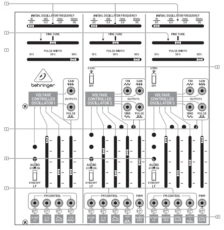
Pre-Wired ConnectionsThe panel silk-screening displays the various connections between modules that have been pre-wired at the factory.For example, in the VOLTAGE CONTROLLED FILTER/RESONATOR VCF section, pre-wired connections from Voltage Controlled Oscillators 1, 2, and 3 into the VCF block are indicated by the labeled boxes at the bottom of the section:

- These labeled, pre-wired inputs correspond to sliders on the panel directly above the label, which enables adjustment of the incoming signal strength.The input jacks directly above each labeled box disconnect the pre-wired connection whenever a 3.5 mm connector is placed into the jack, as indicated by this graphic:Voltage Controlled Oscillators (VCOs)The Voltage Controlled Oscillators (VCOs) electronically generate a repeating wave signal, in a variety of waveforms that can then be shaped, combined, and filtered
- INITIAL OSCILLATOR FREQUENCY – This slider chooses a VCO’s coarse operating frequency in four ranges for audio (10 Hz, 100 Hz, 1 kHz or 10 kHz) or four sub-audio frequency ranges (.03 Hz, .3 Hz, 3.0 Hz or 30 Hz) when the VCO operates as a Low-Frequency Oscillator (LFO). To choose between audio and LFO modes, use the AUDIO/LF sliding switch in the lower left of each VCO.
- FINE TUNE – Use this slider to tune the frequency chosen by the INITIAL OSCILLATOR FREQUENCY slider up or down as needed to find the precise frequency you need.
- PULSE WIDTH – Use this slider to set a default width for the waveform.
- SYNC ON/OFF – Use these sliding switches to lock VCO2 and/or VCO3 with VCO1 so that the synced oscillators act as a single large oscillator that follows the frequency of VCO1 to produce complex sounds.
- OUTPUTS – These output jacks allow you to send out either audio or LFO signals from the VCOs via cables with 3.5 mm connectors. The type of waveform is indicated by the silk-screening associated with the jacks (sawtooth, pulse, sine, triangle, and so on, depending on the specific VCO in use). The PULSE outputs can also be used to mix in signals from the lower LFO section (VCO1), the NOISE GENERATOR section (VCO2), or the ADSR ENVELOPE GENERATOR (VCO3) to produce a composite output signal.
- AUDIO/LF (KYBD ON/OFF) – This sliding switch chooses between audio and low (LFO) frequencies for adjustment with the INITIAL OSCILLATOR FREQUENCY, FINE TUNE, and PULSE WIDTH sliders. When using the VCO as a Low-Frequency Oscillator, keyboard control is automatically disabled. In the AUDIO position, keyboard control is enabled.
- FM CONTROL – Use these inputs to route in external control voltage signals via cables with 3.5 mm connectors. Placing a connector into one of these jacks disconnects the corresponding pre-wired connection indicated directly below the jack.
- PWM – Use this input when you want to route in external control voltages to control the pulse width in place of the PULSE WIDTH slider.Voltage Controlled Filter (VCF)/Resonator SectionThe VOLTAGE CONTROLLED FILTER (VCF)/RESONATOR uses a low-pass filter with a variable cutoff frequency (FC) and resonance (Q). The VCF can be ontrolled by panel controls or by voltage control signals.
- INITIAL FILTER FREQUENCY – This slider sets the low-pass filter to four coarse frequency points at 10 Hz, 100 Hz, 1 kHz, and 10 kHz, which can then be adjusted via the FINE TUNE slider.
- FINE TUNE – Use this slider to make further adjustments up or down from the filter cutoff point set by the INITIAL FILTER FREQUENCY slider.
- RESONANCE – Use this slider to adjust the filter’s Q setting. At the MAX setting, the frequency curve below the filter cutoff becomes sharp and the filter will ring in response to sharp pulses that pass through the filter.
- MODE (4012/4072) – This sliding switch chooses between two classic filter circuits, the 4012 filters (the original filter design with a 16 Hz maximum cutoff frequency) and the 4072 filters (which had a lower maximum cutoff frequency at 11 Hz).
- OUTPUTS – This jack allows you to route out the VCF output for use in other areas of the synthesizer via a cable with a 3.5 mm connector.
- AUDIO – These inputs allow you to route in audio signals via cables with 3.5 mm connectors. Each of these inputs breaks the pre-wired connection when a connector is inserted into the jack.
- CONTROL – Use these inputs for external control voltage signals via cables with 3.5 mm connectors. Each of these inputs breaks the pre-wired connection when a connector is inserted into the jack.AR/ADSR Envelope Generator SectionThese two envelope generators produce controllable, transient waveforms for use mainly with the Voltage Controlled Filter (VCF) and the Voltage Controlled Amplifier (VCA).The AR (Attack-Release) transient generator creates an adjustable transient envelope every time the generator is activated by a gate or trigger voltage. The voltage transient is shaped by the ATTACK TIME and RELEASE TIME sliders, and the AR transient envelope is available at all pre-wired connections with this label:
- ATTACK TIME – This slider controls the shape of the note attack up to an initial fixed peak when a key is depressed or a gate/trigger control voltage enters the circuit.
- RELEASE TIME – Use this slider to control the envelope shape following the key release or release of the gate/trigger voltage.
- MANUAL – Press this button to manually produce a gate signal to trigger both the AR and ADSR circuits.
- TIME FACTOR (x2/x1/x0.5) – Use this sliding switch to choose between three basic time durations for the overall length of the envelope.
- ROUTING SWITCH – Use this sliding switch to choose between the S/H CLOCK pre-wired connection, the GATE IN input or the TRIG IN input. The signal chosen at this switch is also routed through to the ADSR generator.
- OUTPUT – Use this jack to send out an additional AR voltage envelope for use where a pre-wired AR connection is not available.
- S&H CLOCK – This input allows you to substitute another external signal for the Sample & Hold circuit’s output via a cable with a 3.5 mm connector.
- TRIG IN – This input jack allows you to route in a trigger voltage via a cable with a 3.5 mm connector.
- GATE IN – This input jack allows you to route in a gate voltage into the AR and ADSR circuits via a cable with a 3.5 mm connector.The ADSR (Attack-Decay-Sustain-Release) transient generator works similarly to the AR generator, but this circuit creates a more detailed voltage transient every time the generator is triggered by a gate or trigger voltage. The voltage transient is shaped by the ATTACK TIME, DECAY TIME, SUS LEVEL and REL TIME sliders, and the ADSR voltage transient is available at all pre-wired connections with this label:
- ATTACK TIME – This slider controls the shape of the note attack up to an initial fixed peak when a key is depressed a gate/trigger control voltage enters the circuit.
- DECAY TIME – Use this slider to control how quickly the envelope drops from the initial fixed peak.
- SUS LEVEL – This slider controls the level at which the envelope holds after the initial decay following the fixed peak.
- REL TIME – Use this slider to control the envelope shape following the key release or release of the gate/trigger control voltage.
- TIME FACTOR (x2/x1/x0.5) – Use this sliding switch to choose between three basic time durations for the overall length of the envelope.
- OUTPUT – Use this jack to send out an additional ADSR voltage envelope for use where a pre-wired ADSR connection is not available.
- GATE IN – Use this jack to route in a gate signal via a cable with a 3.5 mm connector.
- MANUAL – Press this button to manually produce a gate signal to trigger both the AR and ADSR circuits.
- ROUTING SWITCH – Use this sliding switch to choose between the S/H CLOCK pre-wired connection, the GATE IN input or the TRIG IN input. The signal chosen at this switch is also routed through to the ADSR generator.Voltage Controlled Amplifier SectionThe Voltage Controlled Amplifier (VCA) offers further tone-shaping possibilities in parallel with the Voltage Controlled Filter (VCF) before both are blended in the Mixer section. At maximum gain, the VCA passes signals through at unity gain. At minimum gain, the VCA circuit will not pass a signal.
- INITIAL GAIN – This slider sets the overall gain for the VCA circuit.
- AUDIO – Use these inputs to route audio signals into the VCA and adjust the signal gain using the slider immediately above the inputs. Inserting the 3.5 mm connectors into the jacks will disable the pre-wired VCF and RING MOD connections.
- CNTRL (LIN/EXPL) – These inputs can accept control voltage signals via cables with 3.5 mm connectors. The left input has a linear response, while the right input features an exponential response. Inserting 3.5 mm connectors into these jacks will disable the pre-wired AR and ADSR connections.
- OUTPUT – Use this output to route the final VCA signal out for use where a pre-wired VCA signal is not available.Mixer/Reverb SectionThe Mixer section accepts two inputs that are balanced via the two sliders and then summed into a single signal. After being summed, the combined signal can then be panned before going to the stereo outputs. The Mixer section is prewired with inputs from the VCF and VCA. NOTE: 2600 uses a digital reverb, while BLUE MARVIN eatures a real, onboard spring reverb.
- AUDIO – Use these two inputs to route audio signals into the Mixer via cables with 3.5 mm connectors. Inserting 3.5 mm connectors into these jacks will disable the pre-wired VCF and VCA connections.
- POST-ATTENUATOR OUTPUTS – These two outputs allow you to send signals out immediately following the attenuator sliders, which means the sliders can be used to attenuate audio or control voltage signals for use elsewhere.
- POST-MIXER OUTPUT – This input breaks the signal connection from the Mixer to the PAN slider when a 3.5 mm connector is inserted. Use this input to route in an outside signal for use by the PAN slider. The Mixer output still goes to the Reverb circuit via a pre-wired connection.
- PAN – Use this slider to place the summed Mixer signal where desired in the left-right stereo field before final output.
- MIXER OUT – This output is an additional Mixer output that taps the prewired Mixer connection which feeds into the Reverb circuit.
- REVERB OUT – This output taps the right Reverb signal for use elsewhere.
- LEFT INPUT – Use this input to add an additional signal to the Reverb circuit’s left output. The additional signal will be summed with the left Reverb output and panned hard left in the stereo field.
- RIGHT INPUT – Use this input to add an additional signal to the Reverb circuit’s right output. The additional signal will be summed with the right Reverb output and panned hard right in the stereo field.
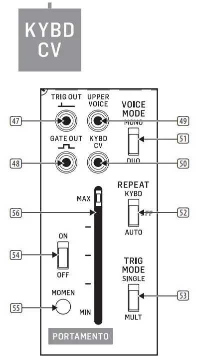
- LOUTPUT/R OUTPUT – The final stereo left-right outputs each have matching parallel pairs of ¼” and 3.5 mm connections. The ¼” outputs can be used to send the final mix to external amplifiers, speakers, or other processing equipment. The parallel 3.5 mm jacks can be used to send the left and right outputs to other synth circuits for further processing.Keyboard/Portamento SectionThe Keyboard section determines how the built-in Low-Frequency Oscillator (LFO) unit works with an external keyboard.The keyboard control voltage is available as a pre-wired connection wherever you see this label:
- TRIG OUT – Use this output to send out a trigger control voltage for use elsewhere via a cable with a 3.5 mm connector.
- GATE OUT – This output can be used to send out a gate control voltage via a cable with a 3.5 mm connector.
- b – This output sends out a control voltage based on the highest note being played on the keyboard while in DUO voice mode.
- KYBD CV – This output sends out the complete keyboard control voltage signal for use elsewhere.
- VOICE MODE(MONO/DUO) – Use this sliding switch to determine whether the keyboard plays one voice at a time (MONO) or two voices simultaneously (DUO).
- REPEAT (KYBD/OFF/AUTO) – Use this sliding switch to control how the keyboard sends trigger signals. When the switch is set to the KYBD position, the keyboard will send out repeating trigger pulses as long a key is held down. In the AUTO setting, the keyboard will send out a stream of trigger pulses based on the synthesizer’s LFO setting. When the switch is in the center OFF position, the keyboard will generate only one trigger pulse per keypress (i.e., the keyboard will revert to “normal” keyboard functionality).
- TRIG MODE (SINGLE/MULT) – When this switch is set to SINGLE, the keyboard will only generate a trigger pulse when a key is played while no other keys are being played. In MULT mode, the keyboard will generate a trigger pulse every time any key is pressed down, even if previously pressed keys are held down.The Portamento function allows one pitch to change gradually to a second pitch at a predetermined rate.
- ON/OFF – This switch turns the Portamento function on or off.
- MOMEN – Pressing this button temporarily activates the Portamento function for as long as the button is held down.
- MAX/MIN – This slider controls the strength of the Portamento effect. The MAX setting provides the most gradual and smooth effect.Low-Frequency Oscillator (LFO) SectionThe unit includes a purpose-built Low-Frequency Oscillator (LFO) primarily meant to function with a keyboard. The LFO has a pre-wired connection to VCO1, as indicated by this label:
- LFO (SAW) – This output allows you to route a sawtooth LFO signal out for use elsewhere via a cable with 3.5 mm connectors.
- LFO (SQUARE) – This output allows you to route a square wave LFO signal out for use elsewhere.
- EXT VIB IN – This input allows you to route in an external LFO signal for blending with the delayed LFO sine wave.
- LFO (SINE) DELAYED – This output can be used to send out a copy of the LFO’s pre-wired sine wave output for use elsewhere. This output signal is delayed at a rate controlled by the VIB DELAY slider.
- LFO SPEED – Controls the base speed of the LFO oscillation.
- VIB DELAY – This slider controls the amount of delay applied to the LFO sine wave.
- VIB DEPTH – This slider controls the intensity of the vibrato effect created by the delayed sine wave LFO signal.Envelope Follower SectionThe Envelope Follower generates an output voltage based on an input signal, depending on the average amplitude of the input signal. The generated control voltage’s characteristics can be adjusted to create various effects when the output is routed to the VCF, VCA, or the VCOs.The input signal can be adjusted via the Preamp, which feeds into the Envelope Follower via a pre-wired connection.The Envelope Follower’s output does not have a pre-wired connection to other sections of the synthesizer.
- PREAMP INPUT – Use this input to route an external signal into the Preamp via a cable with a 3.5 mm connector.
- RANGE (X1000/X100/X10) – Use this sliding switch to determine the base amount of amplification applied to the input signal and then adjusted via the GAIN slider.
- GAIN – This slider determines how strongly the input signal is amplified.
- PREAMP OUTPUT – This output sends out a copy of the Preamp signal for use elsewhere in the synth.
- PREAMP INPUT – This input allows you to bypass the Preamp and route an external signal directly into the Envelope Follower. Alternately, the input signal can be blended with the signal coming into the Envelope Follower via the pre-wired connection.
- SENSITIVITY – This slider controls the sensitivity of the Envelope Follower circuit.
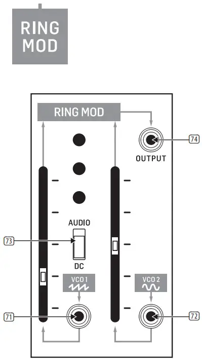
- OUTPUT (ENVELOPE FOLLOWER) – Use this output to route the final Envelope Follower signal out for use elsewhere in the synthesizer via a cable with a 3.5 mm connector.Ring Modulator SectionThe Ring Modulator is a voltage multiplier that combines two input signals to produce a variety of exotic timbres. By default, the two pre-wired signals come into the circuit from VCO1 (sawtooth) and VCO2 (sine).The Ring Modulator output is available as a pre-wired connection wherever you see this label:
- VCO 1 – This input jack allows you to route in an external signal for blending with the pre-wired VCO1 sawtooth signal. The overall gain for this combined signal is adjusted by the adjacent slider.
- VCO 2 – This input jack allows you to route in an external signal for blending with the pre-wired VCO2 sine wave signal. The overall gain for this combined signal is adjusted by the adjacent slider.
- AUDIO/DC – Use this switch to optimize the VCO1 signal path for audio (AUDIO) or control voltage (DC) signals.
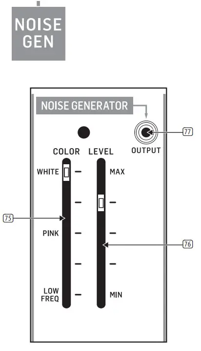
- RING MOD OUTPUT – This jack can be used to send out the final, summed Ring Modulator for use elsewhere where a pre-wired connection is not available.Noise Generator SectionThe Noise Generator produces a noise signal that can be adjusted between white, pink, and low-frequency types of noise, each of which has distinct characteristics and can then be processed in other sections of the synth to design sounds.The Noise Generator output is available as a pre-wired connection wherever you see this label:
- COLOR – Use this slider to move between white noise (WHITE), pink noise (PINK), and low-frequency noise (LOW FREQ).
- LEVEL – This slider controls the overall attenuation of the noise signal prior to output.
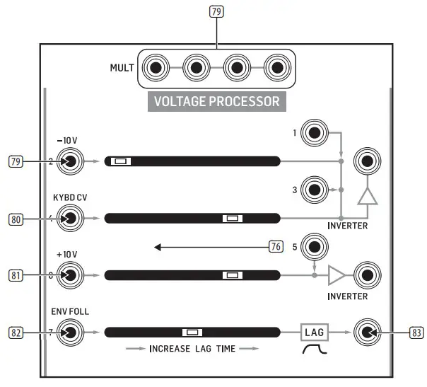
- NOISE GENERATOR OUTPUT – Use this output to send the final noise signal out for use in the synth where a pre-wired connection is not available.Voltage Processor SectionThe Voltage Processor offers three different processors for both audio and control voltage signals. Two of the processors are for mixing and inverting signals, while the third processor applies a variable lag to the signal.The Voltage Processor’s output is not available elsewhere in the synth as a prewired signal, and so requires cables.
- MULT – These linked parallel connections can be used as a patch bay to duplicate and combine signals. The MULT connections can function as both inputs and outputs.Inverter 1Inverter 1 accepts four different inputs, which are summed and then inverted.For example, a +10 V input to INPUT 1 will leave Inverter 1 with a value of -10 V, while an audio signal will be output with the phase reversed 180°.
- -10 V – This input attenuates the input signal by 10 V.
- KYBD CV – This input is optimized for a control voltage signal from a keyboard.Inverter 2Inverter 2 can accept two signals, which are then summed and inverted for output.
- +10 V – This input boosts the input signal by +10 V.Lag ProcessorThe Lag Processor responds to sudden changes in input voltage and slows down those changes by an amount controlled by the slider. For audio signals, the Lag The processor will cut off treble frequencies by increasing amounts, similar to a lowpass filter.
- ENV FOLL – This input can accept both control voltages and audio signals but is optimized to process the Envelope Follower output signal.
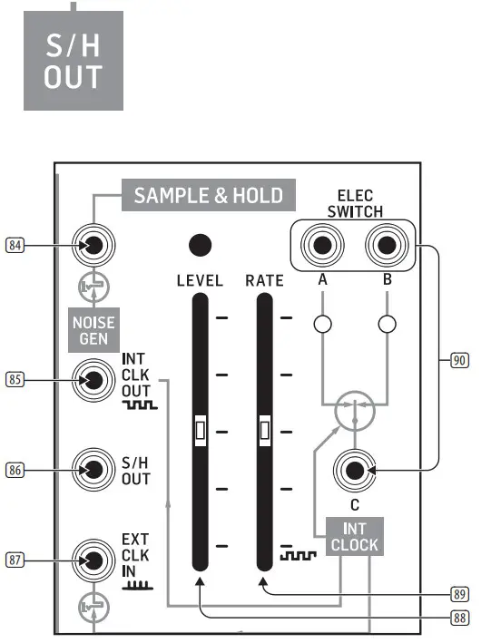
- LAG – This jack sends out the final signal from the Lag Processor.Sample & Hold/Electronic Switch SectionSample & HoldThe Sample & Hold circuit takes an input signal and converts that signal into a stepped output by taking samples of the input signal at set intervals. For example, a smooth sine wave input will appear at the output as a squared-off, approximate version of the original smooth waveform. This stepped waveform can then be sent to other areas of the synthesizer to create exotic sounds and textures.This Sample & Hold circuit has an internal clock generator and a pre-wired connection from the Noise Generator circuit.The Sample & Hold circuit’s output is available as a pre-wired connection wherever you see this label:
- NOISE GENERATOR – This input jack interrupts the Noise Generator input signal when a 3.5 mm connector is inserted into the jack. Use this jack to substitute another signal for the Noise Generator signal.
- INT CLOCK OUT – Use this jack to export the internally generated clock signal for use in other parts of the synthesizer.
- S/H OUT – Use this jack to send out the Sample & Hold circuit’s final signal for use elsewhere in the synthesizer where a pre-wired connection is not available.
- EXT CLK IN – This jack can be used to import an external clock signal to run the Sample & Hold circuit. Placing a 3.5 mm connector into this jack will disable the internal clock generator. Any square or pulse wave generated in other areas of the synthesizer, as well gate or trigger signals from the keyboard can be routed into this jack and used as a clock signal.
- LEVEL – This slider attenuates the input signal before it goes into the Sample & Hold circuit.
- RATE – This slider controls the speed of the internal clock generator and therefore controls how often the Sample & Hold circuit takes a measurement of the input signal. When the internal clock signal is interrupted by the use of the EXT CLK IN input, the RATE slider will not function.Electronic SwitchThe Electronic Switch connections are bidirectional. This circuit can alternate a single input from C between the A and B outputs, or the circuit can route two signals into the A and B jacks and then alternate the C output between the A and B input signals. The rate of back-and-forth switching in both of these scenarios is controlled by the Sample & Hold circuit’s internal clock (or an external clock source-routed in through the EXT CLK IN jack.
- ELEC SWITCH A/B/C – These jacks route signals in and out over cables with 3.5 mm connectors.Phones/Power
- PHONES – Use this jack to connect headphones that use 1/8” plugs and control the output level with the knob immediately below the jack. The headphone jack is connected to the Mixer output.
- POWER – Press this switch to turn the synthesizer on or off. Make sure all the connections are made before turning on the unit.Back Panel
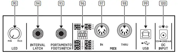
- LED – Use this rotary knob to control the brightness of the LEDs on the front panel.
- INTERVAL LATCH – Use this ¼” jack with an external footswitch to temporarily turn on the interval function. When the VOICE MODE switch is in the DUO position, playing two notes and depressing the footswitch maintains the two-note interval while you play further single notes.
- PORTAMENTO FOOTSWITCH – Use this ¼” jack with an external footswitch to turn the Portamento function on or off.
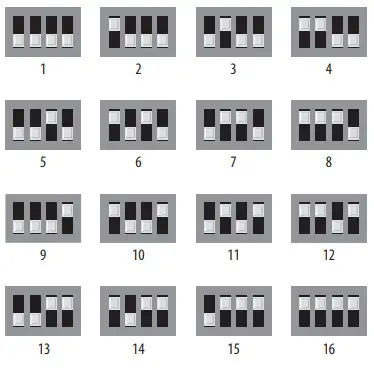
- MIDI CHANNEL SWITCHES – These 4 switches allow you to set the MIDI Channel number from 1 to 16 (see the table printed in this document or refer to the silk-screened switch matrix printed on the back panel).
- MIDI IN – This port receives MIDI data from an external source over a 5-pin DIN connector. This external source will commonly be a MIDI keyboard, an external hardware sequencer, a computer equipped with a MIDI interface, and so on.
- MIDI THRU – This port uses a 5-pin DIN jack is used to pass through MIDI data received at the MIDI IN jack. This MIDI data will commonly be sent to another synthesizer or to a drum machine assigned to a different MIDI Channel.
- USB PORT – This jack allows connection to a computer over a USB type B connection. This synthesizer will show up as a class-compliant USB MIDI device, capable of supporting MIDI in and out.
- DC INPUT – Connect the supplied 12V DC power adapter here. The power adapter can be plugged into an AC outlet capable of supplying from 100V to 240V at 50 Hz/60 Hz. Use only the power adapter supplied.
 Voltage Controlled Filter (VCF)/Resonator SectionThe VOLTAGE CONTROLLED FILTER (VCF)/RESONATOR uses a low-pass filter with a variable cutoff frequency (FC) and resonance (Q). The VCF can be ontrolled by panel controls or by voltage control signals.


Specifications
| Inputs | |
| VCO 1 /2 /3 | |
| Frequency modulation (FM) control | 11 x 33 mm TS jacks, CV range: -10 V to +10V |
| Pulse width modulation (PWM) | 2 x15 mm TS jack, CV range: -S V to +5 V, 1V/1096 |
| VCF | |
| Audio | 5 x3.5 mm TS jacks, SO I& unbalanced |
| Control | 3×3.5 mm TS jacks, CV range: -10 V to +10V |
| ADSR/ AR envelope generator | |
| S&H clock | 1 x3.5 mm TS jack, threshold: > 6V |
| Gate in | 1 x3.5 mm TS jack, threshold: +4 V |
| Trig in | 1 x15 mm TS jack, threshold: +5 V |
| VCA | |
| Audio | 2 x15 mm TS jacks, SO kil unbalanced |
| Control (linear) | 1 x3.5 mm TS jack, CV range: -10 V to +10V |
| Control (exponential) | 1 x3.5 mm TS jack, CV range: -10V to +10V |
| Mixer/ Reverb | |
| Audio | ?KIS mm ‘Wachs SO I& unbalanced |
| Left/ right inputs | 2 x15 mm TS jacks, SO ke unbalanced |
| LFO | |
| Extvib in 1 x IS mm TS jack, SO kD unbalanced | |
| Envelope Follower | |
| Input | 1 x IS mm TS jack, 100k0 unbalanced |
| Preamp input | 1 x3.5 mm TS jack, 100k0 unbalanced |
| Ring Modulator | |
| VCO 1 input | 1 x3.S mm TS jack 100 k0 unbalanced |
| VCO 2 input | I x3.S mm TS jack 100 kO unbalanced |
| Voltage Processor | |
| -10 V input | I x15 mm TS jack, max_ input level: +10V |
| Inputs 1 / 3 / S | 3 x15 mm TS jacks, max. input level: +10V |
| Keyboard CV input | I x15 mm TS jack, max. input level: +10V |
| +10 V input | 1 x3.S mm TS jack, max. input level: +10V |
| Env follower input | 1 x3.S mm TS jack, max. input level: +10V |
| Sample & Hold | |
| Noise gen input | 1 x15 mm Jack, 50 kfl unbalanced |
| Ext clock in | 1 x15 mm Mack, threshold: > 3 V |
| Back Panel | |
| Interval latch | 1 x Mr IRS |
| Portamento footswitch | 1 x14″ IRS |
| OutputsVCO 1/2/3 | |
| Outputs (saw) | 3 x 3.5 mm TS jacks, 1 kO unbalanced |
| Outputs (pulse) | 3 x 3.5 mm TS jacks, 800 ft unbalanced |
| Outputs (tri) | 2 x 3.5 mm TS jacks, 1 Id/ unbalanced (VCO 2 / 3 only) |
| Outputs (sine) | 2 x 3.5 mm TS jacks, 1 kO unbalanced (VCO 2 / 3 only) |
| VCF | |
| Outputs | 1 x 3.5 mm TS jack, 1 kit unbalanced |
| ADSR / AR Envelope Generator | |
| Output | I 2 x 3.5 mm TS jacks, CV range:0 V to +10 V |
| VCA | |
| Output | 1 x 3.5 mm TS jack, 1 Id) unbalanced |
| Mixer /reverb | |
| Post-attenuator outputs | 2 x 3.5 mm TS jacks, 1 kit unbalanced |
| Post-mixer output | 1 x 3.5 mm TS jack, 1 Id) unbalanced |
| L / R outputs | 2 x 3/4″ TS, 5000 unbalanced2 x 3.5 mm TS jacks, 500 II unbalanced |
| LFO | |
| LFO (triangle) | 1 x 3.5 mm TS jack, 1 kO unbalanced |
| LFO (square) | 1 x 3.5 mm TS jack, 1.8 kO unbalanced |
| LFO delayed (sine) | 1 x 3.5 mm TS jack, 1 kit unbalanced |
| Envelope follower | |
| Output (preamp x1000) | 1 x 3.5 mm TS jack, max. output gain: +60 dBu |
| Output (preamp x100) | 1 x 3.5 mm TS jack, max. output gain: +40 dBu |
| Output (preamp x10 ) | 1 x 3.5 mm TS jack, max. output gain: +20 dBu |
| Output (env follower) | 1 x 3.5 mm TS jack, max. output level: +14 V |
| Ring modulator | |
| Output | 1 x 3.5 mm TS jack, output level: -10Y to +10 V |
| Noise generator | |
| Output | 1 x 3.5 mm TS jack, output level: -10Y to +10 V |
| Voltage processor | |
| Inverter 1 output | 1 x 3.5 mm TS jack, output level: -10 V to +10 V |
| Inverter 2 output | 1 x 3.5 mm TS jack, output level: -10Y to +10 V |
| Lag output | 1 x 3.5 mm TS jack, output level: -10V to +10 V |
| Sample & hold | |
| Internal dock out | 1 x 3.5 mm TS jack, max. output level: +10 V |
| S/11 out | 1 x 3.5 mm TS jack, max. output level: +14 V |
| Portamento / keyboard | |
| Trig out | 1 x 3.5 mm TS jack, output level: +14V |
| Upper voice | 1 x 3.5 mm TS jack, max. output level: +10 V |
| Gate out | 1 x 3.5 mm TS jack, output level: +10 V |
| Keyboard CV output | 1 x 3.5 mm TS jack, max. output level: +7 V |
| Phones | |
| Type 1 x1411 TRS jack, stereo | |
| Max. output level 5 dBu | |
| Output impedance 80Dual Inputs / OutputsVoltage Processor | |
| Mu It inputs/outputs | 4x 3.5 mm TS jacks, all direct connection. |
| Sample & Hold | |
| Elec switch A / B/C | 3 x 3.5 mm TS jacks, A / C on or B/C on |
| MIDI in /thru | 2 x 5-pin DIN, 16 channels |
| USB (MIDI) | Type B |
| Controls | |
| VC01/2/3 | |
| Sliders | Initial oscillator frequency 10 (0.03)Hz / 100 (0.3) Hz / 1(3.0 Hz) kHz;10 (30 Hz) kHz, selectable Fine tunePulse width: 10% to 90% Audio / II (Kybd on /off) Sync on / off (W02 / 3 only) S /H slider (VCO 1 / 2 only) ADSRLEO (VCO 1 only)VCO 1 (pulse, VCO ? only) VCO 2 (sine, VCO 3 only) Noise generator (WO 2 / 3 only) |
| Switches | audio/LI (kybd on /off) Sync on /off (VCO 1 / 2 only) |
| VCF /Resonator | |
| Sliders | Initial filter frequencyFine-tuneResonanceRing modulator VCO I (pulse) VCO 2 (pulse) VCO 3 (saw) Noise generator Keyboard CV ADSRVCO 2 (sine) |
| Switches | Mode.4012 /4072, selectable |
| AR / ADSR envelope generator | |
| Sliders | “Attack time Decay time Sus levelRelease time Time factor, Manual.’ |
| Switches | Time factor. x0.5 /x1 /x2, selectable |
| VCA | |
| Sliders | Initial gainYuRing modulator ARADS |
| Mixer/reverb | |
| Sliders | VCF VCA Reverb I. / RPan |
| LFO | |
| Sliders | LEO speedVd) delayVia depth |
| Envelope follower | |
| Sliders | Input gain Preamp gain |
| Switches | Gain range:x10 (20 d6) /x100 (40 dB)/ x1000 (60 d13) , selectable |
| Ring modulator | |
| Sliders | VCO I (saw)VCO 2 (sine) |
| Noise generator | |
| Sliders I Color create / pink/white, adjustable Level |
| Controls | |
| Voltage processor | |
| -10 V gainSliders Keyboard CV gain+10 V gainIncrease lag time | |
| Sample & hold | |
| Sliders | Level Rate |
| Portamento | |
| Sliders | Portamento: min to max |
| Switches | On /off Momen |
| Keyboard | |
| Switches | Voice mode: mono / duo, selectable Repeat: keyboard /off/ auto, selectable Trig mode: single / multi, selectable |
| Phones level | 1 x rotary knob: 0 to 10 |
| Power | 1 x rocker switch |
| Back panel | |
| LED | 1 x rotary knob: min to max |
| MIDI channel switches | 4x DIP switches |
| Synthesizer Architecture | |
| Number of voices | Multiphonic |
| Type | Analog |
| VCO | 3 (0.03 Hz to 40 kHz in 4 overlapping ranges) |
| LFO | 1(0.25 Hz to 25 Hz) |
| VCF | 1 x 4-pole low pass (24 dB/Oct. slope) |
| VCA | 1 |
| Envelopes | AR, ADSR |
| Effects | Digital spring reverb |
| USB | |
| Type | Class-compliant USB 2.0, type B |
| Supported operating systems | Windows 7 or higher Mac OS X 10.6.8 or higher |
| Power | |
| External power adapter | 12 V DC, 2000 mA |
| Power consumption | Max. 15 W |
| Physical | |
| Standard operating temperature range | 5° C to 40°C (41° F to 104° F) |
| Dimensions | 482 x 356 x 108 mm (19 x 14 x 4.3″) |
| Rack units | 95 HP |
| Weight | 5.1 kg (11.22 lbs) |

FEDERAL COMMUNICATIONS COMMISSION COMPLIANCE INFORMATION
 Responsible Party Name: Music Tribe Commercial NV Inc.Address: 901 Grier Drive Las Vegas, NV 89118 USAPhone Number: +1 747 237 50332600This equipment has been tested and found to comply with the limits for a Class B digital device, pursuant to part 15 of the FCC Rules. These limits are designed to provide reasonable protection against harmful interference in a residential installation. This equipment generates, uses, and can radiate radio frequency energy and, if not installed and used in accordance with the instructions, may cause harmful interference to radio communications. However, there is no guarantee that interference will not occur in a particular installation. If this equipment does cause harmful interference to radio or television reception, which can be determined by turning the equipment off and on, the user is encouraged to try to correct the interference by one or more of the following measures:
- Reorient or relocate the receiving antenna.
- Increase the separation between the equipment and receiver.
- Connect the equipment into an outlet on a circuit different from that to which the receiver is connected.
- Consult the dealer or an experienced radio/TV technician for help.
This device complies with Part 15 of the FCC rules. Operation is subject to the following two conditions:
- this device may not cause harmful interference, and
- this device must accept any interference received, including interference that may cause undesired operation.
 report this ad
Important information:Changes or modifications to the equipment not expressly approved by Music Tribe can void the user’s authority to use the equipment.
We Hear You![]()
[xyz-ips snippet=”download-snippet”]