
Quick Start Guide
921 VOLTAGE CONTROLLED OSCILLATORLegendary Analog VCO Module for Eurorack
Controls
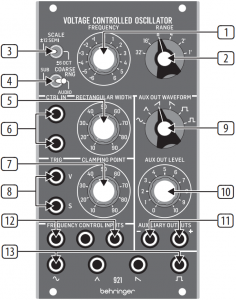
- FREQUENCY – Use this knob to set the oscillator frequency. The frequency settings for this knob are controlled by the COARSE RNG and SCALE toggle switches, as well as the RANGE rotary switch.
- RANGE - This knob sets the general frequency range of the oscillator in one-octave steps, which can then be adjusted up or down with the FREQUENCY knob.
- SCALE – This switch controls whether the frequency knob scale is ±6 octaves or ±12 semitones, which gives finer frequency control.
- COARSE RNG – This switch controls whether the oscillator frequency functions in the audio range or in a lower frequency range that extends below the audio threshold.
- RECTANGULAR WIDTH – Use this knob to set a default width for the rectangular waveform. The width can then be further controlled and varied by control voltages routed in via the CNTRL IN jacks.
- CNTRL IN – These summed jacks allow control voltage and modulation signals for the rectangular waveform to be routed in via cables with 3.5 mm TS connectors.
- CLAMPING POINT – Use this knob to set the point at which the oscillator waveform resets.
- TRIG (V/S) – These jacks allow control signals for the clamping point to be routed in via cables with 3.5 mm TS connectors. The clamping point can be triggered with a V-Trig (voltage trigger) signal via the V jack, or a S-Trig (switch trigger) signal via the S jack.
- AUX OUT WAVEFORM – Use this knob to select a waveform for the auxiliary output signal, including sine, triangular, sawtooth, inverted sawtooth, square and inverted square waveforms.
- AUX OUT LEVEL - Use this knob to adjust the output level for the AUXILIARY OUTPUT jacks.
- AUXILIARY OUTPUTS - Use these jacks to route an auxiliary waveform signal out of the module via cables with 3.5 mm TS connectors.
- FREQUENCY CONTROL INPUTS – Use these summed jacks to route control voltage and modulation signals into the oscillator via cables with 3.5 mm connectors.
- WAVEFORM OUTPUTS – Use these jacks to route oscillator signals out of the module via cables with 3.5 mm jacks. Four waveforms are available: sine, triangular, sawtooth and rectangular.
Power Connection

The 921 VOLTAGE CONTROLLED OSCILLATOR module comes with the required power cable for connecting to a standard Eurorack power supply system. Follow these steps to connect power to the module.It is easier to make these connections before the module has been mounted into a rack case.
- Turn the power supply or rack case power off and disconnect the power cable.
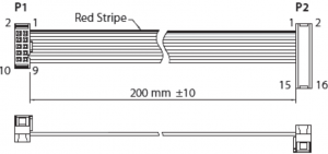
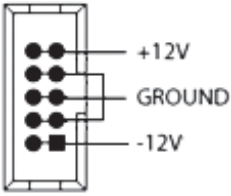
- Insert the 16-pin connector on the power cable into the socket on the power supply or rack case. The connector has a tab that will align with the gap in the socket, so it cannot be inserted incorrectly. If the power supply does not have a keyed socket, be sure to orient pin 1 (-12 V) with the red stripe on the cable.
![]()
2 921 VOLTAGE CONTROLLED OSCILLATOR
3. Insert the 10-pin connector into the socket on the back of the module. The connector has a tab that will align with the socket for correct orientation.4. After both ends of the power cable have been securely attached, you may mount the module in a case and turn on the power supply.
Installation
The necessary screws are included with the module for mounting in a Eurorack case. Connect the power cable before mounting.
Depending on the rack case, there may be a series of fixed holes spaced 2 HP apart along the length of the case, or a track that allows individual threaded plates to slide along the length of the case. The free-moving threaded plates allow precise positioning of the module, but each plate should be positioned in the approximate relation to the mounting holes in your module before attaching the screws.
Hold the module against the Eurorack rails so that each of the mounting holes are aligned with a threaded rail or threaded plate. Attach the screws part way to start, which will allow small adjustments to the positioning while you get them all aligned. After the final position has been established, tighten the screws down.
Tuning Procedure
This procedure tunes the 921 VOLTAGE CONTROLLED OSCILLATOR module’s “octave scaling” to an exact 1 V/oct. calibration to facilitate precise control.
- Power up the 921 module and allow it to warm up for a few minutes.
- Prepare the following control settings on the 921 module:a. Set the SCALE toggle switch to the ±12 SEMI position.b. Set the RANGE toggle switch to the AUDIO position.c. Set the RANGE rotary switch to 2′.d. Set the FREQUENCY control knob so that the sawtooth output is exactly 640 Hz as measured with an accurate frequency meter.e. Make sure none of the FREQUENCY CONTROL INPUTS jacks are connected.Note: All adjustment trimmers are accessible from the 921 module’s underside. Note the positions of the SCALE and HI ADJ multi-turn trimmers, and make sure you have suitable tools to adjust the trimmers if required.
- Fine-tune the 921 oscillator’s low-frequency scaling via the following steps:a. Apply exactly -2 V to a FREQUENCY CONTROL INPUTS input jack. (A 921A module can be used to supply the -2 V or use a similar low-impedance stable-voltage source.)b. Trim the SCALE trimmer to set 160 Hz, then remove the -2 V input and readjust the FREQUENCY knob to 640 Hz.c. Repeat this cycle until both 160 Hz and 640 Hz are accurate to ±1 Hz when the -2 V is plugged in and out of the FREQUENCY CONTROL INPUTS jack.
- Fine-tune the 921 oscillator’s high-frequency scaling via the following steps:a. With no FREQUENCY CONTROL INPUTS jack connected, check the frequency is still set for 640 Hz output, then apply exactly +2 V to the FREQUENCY CONTROL INPUTS input.b. Trim the HI ADJ trimmer to set the 921 sawtooth output to exactly 2.560 kHz.c. Re-check that 640 Hz is still correct when the +2 V input is removed.d. Repeat as required.
Specifications
Signal Connections
| Frequency control inputs | 3 x 3.5 mm jacks, summed, 1 V/oct. |
| Rectangular width control inputs | 2 x 3.5 mm jacks, summed, 1 V/15% |
| Input Impedance | 100 kΩ, unbalanced |
| Maximum input level | -6 to +6 V |
| Clamping point trigger inputs | 2 x 3.5 mm jacks (1 x V-trig, 1 x S-trig) |
| V-trig input impedance | 10 kΩ, unbalanced |
| S-trig input impedance | 30 kΩ, unbalanced |
| Maximum input level | +12 V |
| Auxiliary outputs | 1 x 3.5 mm jack, mono, +/- polarity |
| Output Impedance | 50 Ω, unbalanced |
| Maximum output level | +10 dBu |
| Waveform outputs | 4 x 3.5 mm jacks, mono |
| Waveforms | Sine, triangular, sawtooth, rectangular |
| Output Impedance | < 800 Ω, unbalanced |
| Output level | Typically -4 dBu |
Controls
| Scale | 1 x toggle switch ±6 octaves / ±12 semitone, selectable |
| Coarse range | 1 x toggle switch Sub-audio range, typically 0.01 Hz to 800 Hz Audio range, typically 1 Hz to 80 kHz |
| Frequency | 1 x rotary knob ±6 octaves |
| Range | 1 x rotary switch 32′ / 16′ / 8′ / 4′ / 2′ / 1′, selectable |
| Rectangular width | 1 x rotary knob 10% to 90%, selectable |
| Clamping point | 1 x rotary knob 10% to 90%, selectable |
| Aux out waveform | 1 x rotary switch Sine / triangular / inverted sawtooth / sawtooth / rectangular / inverted rectangular, selectable |
| Aux out level | 1 x rotary knob Off to +10 dBu, selectable |
Power
| Power supply | Eurorack |
| Current draw | 50 mA (+12 V), 50 mA (-12 V) |
Physical
| Dimensions | 45 x 71 x 129 mm (1.8 x 2.8 x 5.1″) |
| Rack units | 14 HP |
| Weight | 0.18 kg (0.40 lbs) |
LEGAL DISCLAIMER
Music Tribe accepts no liability for any loss which may be suffered by any person who relies either wholly or in part upon any description, photograph, or statement contained herein. Technical specifications, appearances and other information are subject to change without notice. All trademarks are the property of their respective owners. Midas, Klark Teknik, Lab Gruppen, Lake, Tannoy, Turbosound, TC Electronic, TC Helicon, Behringer, Bugera, Auratone and Coolaudio are trademarks or registered trademarks of Music Tribe Global Brands Ltd. © Music Tribe Global Brands Ltd. 2020 All rights reserved.
LIMITED WARRANTY
For the applicable warranty terms and conditions and additional information regarding Music Tribe’s Limited Warranty, please see complete details online at musictribe.com/warranty.
Zhongshan Eurotec Electronics LimitedNo. 10 Wanmei Road, South China Modern Chinese Medicine Park, Nanlang Town, 528451, Zhongshan City, Guangdong Province, China
We Hear You
![]()
References
[xyz-ips snippet=”download-snippet”]