
![]()
Important safety instructions
![]()
 Terminals marked with this symbol carry an electrical current of sufficient magnitude to constitute a risk of electric shock. Use only high-quality professional speaker cables with ¼” TS or twist-locking plugs pre-installed. All other installation or modifications should be performed only by qualified personnel.
This symbol, wherever it appears, alerts you to the presence of uninsulated dangerous voltage inside the enclosure – voltage that may be sufficient to constitute arisk of shock.
This symbol, wherever it appears, alerts you to important operating and maintenance instructions in the accompanying literature.Please read the manual.
CautionTo reduce the risk of electric shock, do not remove the top cover (or the rear section). No user-serviceable parts inside. Refer servicing to qualified personnel.
CautionTo reduce the risk of fire or electric shock, do not expose this appliance to rain and moisture. The apparatus shall not be exposed to dripping or splashing liquids and no objects filled with liquids, such as vases, shall be placed on the apparatus.
CautionThese service instructions are for use by qualified service personnel only. To reduce the risk of electric shock do not perform any servicing other than that contained in the operation instructions. Repairs have to be performed by qualified service personnel.
- Read these instructions.
- Keep these instructions.
- Heed all warnings.
- Follow all instructions.
- Do not use this apparatus near water.
- Clean only with a dry cloth.
- Do not block any ventilation openings. Install in accordance with the manufacturer’s instructions.
- Do not install near any heat sources such as radiators, heat registers, stoves, or other apparatus (including amplifiers) that produce heat.
- Do not defeat the safety purpose of the polarized or grounding-type plug. A polarized plug has two blades with one wider than the other. A grounding-type plug has two blades and a third grounding prong. The wide blade or the third prong is provided for your safety. If the provided plug does not fit into your outlet, consult an electrician for the replacement of the obsolete outlet.
- Protect the power cord from being walked on or pinched particularly at plugs, convenience receptacles, and the point where they exit from the apparatus.
- Use only attachments/accessories specified by the manufacturer.

- Use only with the cart, stand, tripod, bracket or table specified by the manufacturer, or sold with the apparatus. When a car is used, use caution when moving the cart/apparatus combination to avoid injury from tip-over.
- Unplug this apparatus during lightning storms or when unused for long periods of time.
- Refer all servicing to qualified service personnel. Servicing is required when the apparatus has been damaged in any way, such as power supply cord or plug is damaged, liquid has been spilled or objects have fallen into the apparatus, the apparatus has been exposed to rain or moisture, does not operate normally, or has been dropped.
- The apparatus shall be connected to a MAINS socket outlet with a protective earthing connection.
- Where the MAINS plug or an appliance coupler is used as the disconnect device, the disconnect device shall remain readily operable.
- Correct disposal of this product: This symbol indicates that this product must not be disposed of with household waste, according to the WEEE Directive (2012/19/EU) and your national law. This product should be taken to a collection center licensed for the recycling of waste electrical and electronic equipment (EEE). The mishandling of this type of waste could have a possible negative impact on the environment and human health due to potentially hazardous substances that are generally associated with EEE. At the same time, your cooperation in the correct disposal of this product will contribute to the efficient use of natural resources. For more information about where you can take your waste equipment for recycling, please contact your local city office or your household waste collection service.
- Do not install in a confined space, such as a bookcase or similar unit.
- Do not place naked flame sources, such as lighted candles, on the apparatus.
- Please keep the environmental aspects of battery disposal in mind. Batteries must be disposed of at a battery collection point.
- Use this apparatus in tropical and/or moderate climates.

LEGAL DISCLAIMERMusic Tribe accepts no liability for any loss which may be suffered by any person who relies either wholly on or in part upon any description, photograph, or statement contained herein. Technical specifications, appearances, and other information are subject to change without notice. All trademarks are the property of their respective owners. Midas, Klark Teknik, Lab Gruppen, Lake, Tannoy, Turbosound, TC Electronic, TC Helicon, Behringer, Bugera, Oberheim, Auratone, and Coolaudio are trademarks or registered trademarks of Music Tribe Global Brands Ltd. © Music Tribe Global Brands Ltd. 2019 All rights reserved.
LIMITED WARRANTYFor the applicable warranty terms and conditions and additional information regarding Music Tribe’s Limited Warranty, please see complete details online at musictribe.com/warranty.
Zhongshan Eurotec Electronics LimitedNo. 10 Wanmei Road, South China Modern ChineseMedicine Park, Nanlang Town, 528451, Zhongshan City,Guangdong Province, China.
MS-1 Hook-up
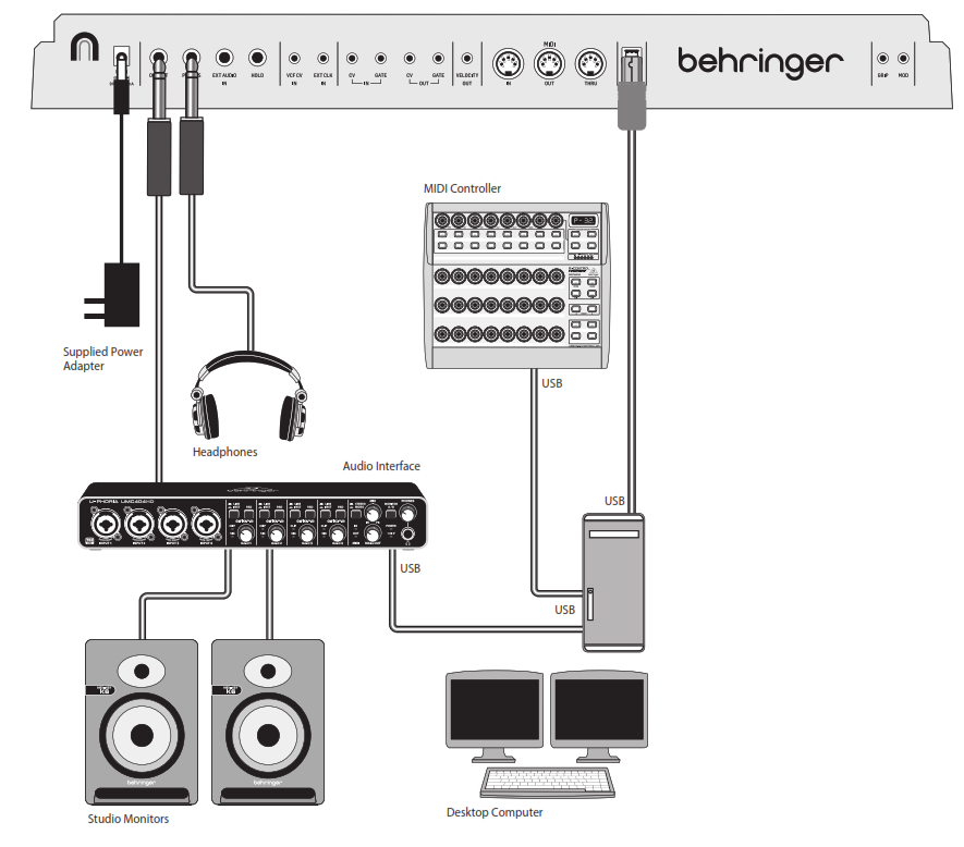
Step 1: Hook-Up
Studio System
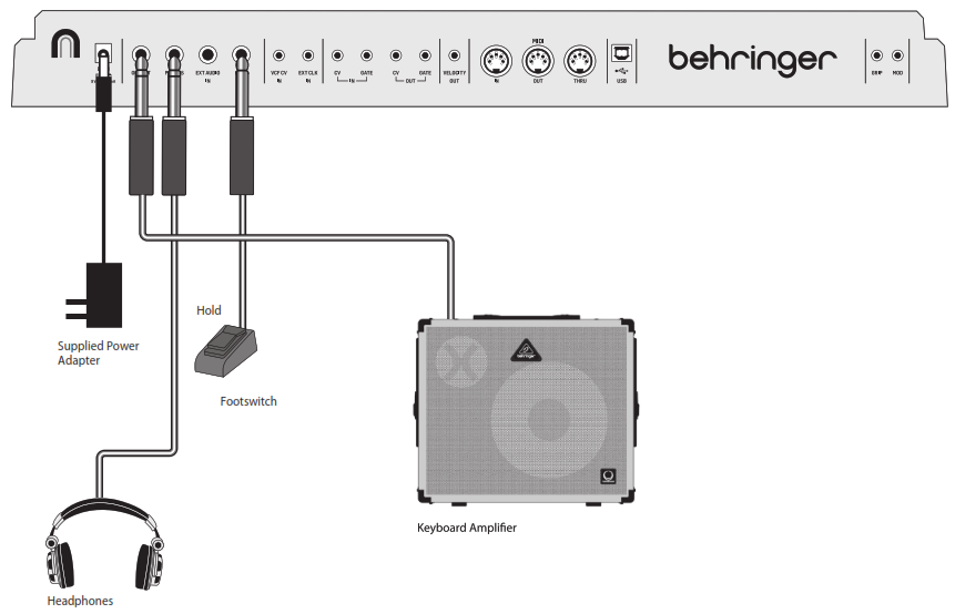
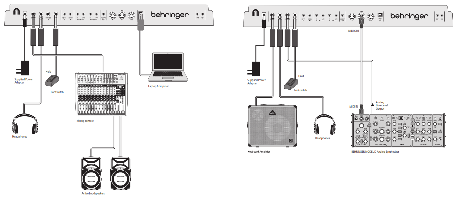
MS-1 Hook-up
Live System
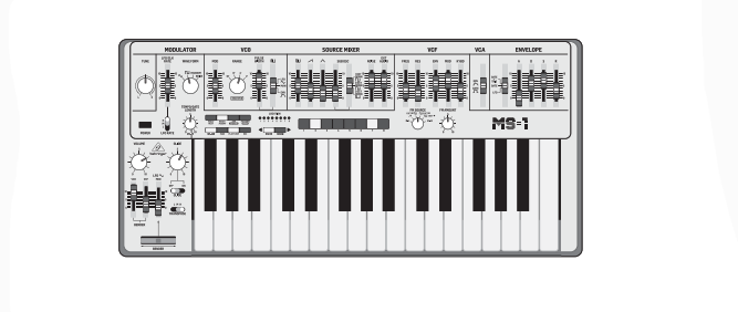
 MS-1 Controls
Step 2: Controls
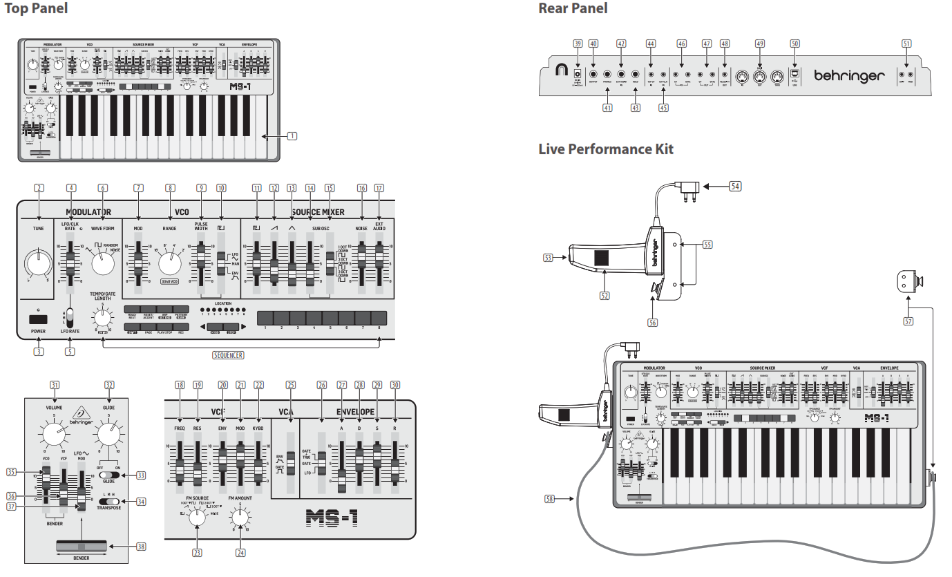
(1) KEYBOARD – the keyboard has 32 semi-weighted, full-size keys.(2) TUNE – adjust the frequency of the main VCO of the synthesizer.(3) POWER – turn the synthesizer on or off. Make sure all the connections are made before turning on the unit. The LED shows when power is applied and the unit is turned on.Modulator Section(4) LFO/CLK RATE – adjust the frequency of the modulation LFO. The LED blinks at the current rate.(5) LFO RATE – select the frequency range of the LFO rate fader from Low, Medium, or High.(6) WAVEFORM – select the waveform from triangular, square wave, random, or noise.VCO Section(7) MOD DEPTH – adjust the level of modulation of the VCO.(8) RANGE – select the overall frequency range (octave) of the VCO from 16’, 8’, 4’, and 2’.(9) PULSE WIDTH – adjust the pulse width of the VCO when the pulse modulation source switch is set to Manual. For LFO and ENV, it adjusts the effect of the modulation.(10) PULSE WIDTH MODULATION SOURCE– select from LFO triangular waveform, Manual, or Envelope.Source Mixer Section(11) PULSE – adjust the level of the pulse waveform.(12) SAW WAVE – adjust the level of the sawtooth waveform.(13) TRIANGULAR – adjust the level of the triangular waveform.(14) SUB OSCILLATOR – adjust the level of the sub-oscillator.(15) SUB OSC TYPE – select the type of sub-oscillator, from 1 octave down, 2 octaves down, or a narrower pulse width at 2 octaves down.(16) NOISE – adjust the level of noise.(17) EXT AUDIO – adjust the level of incoming audio from an external source.Sequencer SectionSEQUENCER – see details on pages 16 and 36.VCF Section(18) FREQ – adjust the cutoff frequency of the VCF. Frequencies above the cutoff are attenuated.(19) RES – adjusts the amount of volume level boost (resonance) given at the cut-off frequency.(20) ENV – adjust the amount of effect the envelope has on the VCF.(21) MOD – adjust the amount of effect the modulation has on the VCF.(22) KYBD – adjust the amount of effect the keyboard has on the VCF.(23) FM SOURCE – select the source of FM modulation on the VCF from pulse, sawtooth, 1 octave down square wave, 2 octaves down square wave, 2 octaves down pulse, and noise.(24) FM AMOUNT – adjust the effect of FM modulation on the VCF.VCA Section(25) ENV/GATE – select if the VCA is affected by the envelope controls, or by the gate.Envelope SectionWhen applied to the VCA, the ADSR envelope is used to control the level of the note being played over time. When applied to the VCF, the ADSR envelope is used to control the cut-off frequency of the filter for each note played over time. In addition, the ADSR envelope can also affect the VCO pulse width modulation.Note that the ATTACK, DECAY, and RELEASE stages are measured in units of time, and the SUSTAIN stage is measured in units of level.(26) GATE + TRIG – a new envelope is triggered at each keypress.GATE – when a new note is pressed, a new envelope is trigged after the current one is done.LFO – the envelope is triggered by the LFO.(27) A-ATTACK – this adjusts the time for the level to reach a maximum after a key is pressed.(28) D-DECAY – this adjusts the time to decay down to the SUSTAIN level after the attack time is over.(29) S-SUSTAIN – this sets the sustain level reached after the attack and decay time are over.(30) RE-RELEASE – this adjusts the time it takes for the signal to decay once the key is released.Control Section(31) VOLUME – adjust the volume level of the main output and headphones output. Turn this down before turning the power on, or before putting on headphones.(32) GLIDE – adjust the amount of Glide time (Portamento) between notes on the keyboard.(33) GLIDE ON/OFF – turn the GLIDE on or off.(34) TRANSPOSE – adjust the keyboard in one-octave steps, from Low, Medium, and High.(35) VCO FADER – adjust the effect of the bender controls on the VCO.(36) VCF FADER – adjust the effect of the bender controls on the VCF.(37) LFO MOD FADER – adjust the amount of LFO modulation added when the MOD switch on the grip is pressed, or the BENDER (38) is moved up.(38) BENDER – move left or right to adjust the frequency of the VCO and/or the cut-off frequency of the VCF. The level of the effect depends on the setting of the nearby VCO andVCF faders. Move it up to add LFO modulation. The modulation effect depends upon the setting of the LFO MOD fader and other LFO controls.Rear Panel(39) DC INPUT – Connect the supplied DC power adapter here. The power adapter can be plugged into an AC outlet capable of supplying from 100V to 240V at 50 Hz/60 Hz. Use only the power adapter supplied.(40) MAIN OUTPUT – connect this output to the line-level inputs of mixers, keyboard amplifiers, or powered speakers for example.(41) PHONES – connect your headphones to this output. Make sure the volume is turned down before putting on headphones.(42) EXT AUDIO INPUT – this input can be connected to the line-level audio output from an external audio device. Adjust the level using the EXT AUDIO fader in the SOURCE MIXER section.(43) HOLD – an optional footswitch can be connected here, to hold or release any pattern playing in the Sequencer, and in normal performance.(44) VCF CV INPUT – the VCF can be controlled by an external control voltage connected here.(45) EXT CLK INPUT – an external clock signal can be applied here.(46) CV/GATE INPUT – these inputs allow the connection of control voltage and gate signals from compatible external devices such as modular synthesizer equipment.(47) CV/GATE OUTPUT – these outputs allow the connection of control voltage and gate signals to compatible external devices such as modular synthesizer equipment.(48) VELOCITY OUT – outputs a variable control voltage based on the key velocity.(49) MIDI Connections – these 3 standard 5-pin DIN Jacks allow connections to other MIDI equipment in your system. MIDI IN – receives MIDI data from an external source. This will commonly be another MIDI keyboard, an external hardware sequencer, a computer equipped with a MIDI interface, etc. MIDI THRU – passes through MIDI data received at the MIDI INPUT. MIDI OUT – sends MIDI data to an application(50) USB PORT – This USB type B jack allows connection to a computer. The MS-1 will show up as a class-compliant USB MIDI device, capable of supporting MIDI in and out. USB MIDI IN – accepts incoming MIDI data from an application. USB MIDI OUT – sends MIDI data to an application.(51) GRIP/ MOD – the connector of the live performance, grip attaches here.Live Performance Kit(52) BENDER – adjusts the frequency of the VCO and/or the cut-off frequency of the VCF. The level of the effect depends on the setting of the VCO and VCF Bender faders. This control only increases the frequency. The main unit bender can also be used at the same time.(53) MOD – press and hold to add LFO modulation. The level of the effect depends upon the setting of the LFO mod fader and the other LFO controls.(54) CONNECTOR – fit into the GRIP and MOD connectors in the main unit rear panel.(55) MOUNTING HOLES – fit the supplied screws in these holes to secure the handle to the left side of the main unit.(56) STRAP POINT 1 – connect one end of the supplied strap here.(57) STRAP POINT 2 – secure this to the right side of the main unit with the supplied screws.(58) STRAP – the supplied strap attaches to the 2 strap points.
MS-1 ControlsStep 2: Controls
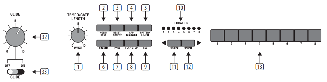
Sequencer Section(1) TEMPO/GATE LENGTH – this knob controls the sequencer and arpeggio tempo. During step editing, it also controls the GATE length. If SHIFT is held, then the knob also adjusts the SWING.(2) HOLD/REST – during pattern playback, this allows you to hold the current step. During step editing, it allows you to enter the rest.(3) RESET/ACCENT – during playback, this allows you to reset the pattern back to step 1. During step editing, you can add an accent to a step.(4) ARP (SET END) – In ARP mode, an arpeggio will play, based on the held notes on the keyboard.Double-press to play and hold the arpeggio. In Sequencer mode, pressing SHIFT and SET END together, followed by a STEP switch, will allow that step to become the end of the current pattern.(5) PATTERN (BANK) – This switch is used to access either the current pattern or bank number, as follows:PATTERN: Press PATTERN and one of the 8 LOCATION LEDs will show the current pattern number (from 1 to 8). To change to a different pattern number, keep the PATTERN switch held down and press any of the STEP switches (1 to 8), or press <KYBD to decrease, or STEP> to increase the pattern number.BANK: Press SHIFT and PATTERN, and one of the 8 LOCATION LEDs will show the current bank number (from 1 to 8). To change to a different bank number, keep both SHIFT and BANK held down, and press any of the STEP switches (1 to 8), or press <KYBD to decrease, or STEP> to increase the bank number.
(6) SHIFT – This is used to access the secondary features of some of the other sequencer controls, such as SET END, BANK, SWING, KYDB, and STEP. Hold down SHIFT and the other switch at the same time. For example, SHIFT + PATTERN (BANK) will show the current BANK number in the LOCATOR LEDs.(7) PAGE – each pattern can be up to 32 steps in length. This switch allows you to show each of the 4 pages of 8 steps each. The LOCATION LEDs 1 to 4, show which page you are on. If a pattern is playing, the STEP LEDs will show the steps in use on the current page.(8) PLAY/STOP – starts or stops the playback of the pattern. If SHIFT is held at the same time, then this is the start of the pattern saving procedure, described below.(9) REC – press this to begin the recording of a new pattern. This is also used with SHIFT during the pattern saving procedure.(10) LOCATION – these multi-colored LEDs show various details, such as the current PATTERN number, current BANK number, current PAGE, and GATE LENGTH. (11) KYBD – press SHIFT + KYBD to change the sequencer to keyboard mode.(12) STEP – press SHIFT + STEP to change the sequencer to STEP mode.(13) STEP SWITCHES – these multi-function switches allow you to view and select individual pattern steps, select a pattern number, select a pattern bank. They are used during the recording of a pattern to show the current step. Active steps are illuminated with a steady red LED, and the current step flashes red.(32) GLIDE – during step editing, this knob can be used to add a Ratchet by splitting the current step into 1, 2, 3, or 4 parts. Hold down SHIFT and turn the knob to split the current step into the number of parts shown by the LOCATOR LEDs (yellow) 1 to 4. The GLIDE switch (33) does not have to be on for the Ratchet to work.
MS-1 Getting startedStep 3: Getting startedOVERVIEWThis “getting started” guide will help you set up the MS-1 analog synthesizer and briefly introduce its capabilities.CONNECTIONTo connect the MS-1 to your system, please consult the connection guide earlier in this document. Caution: Do not overload the 3.5 mm inputs. They can only accept the correct level of voltages as shown in the specification tables. The 3.5 mm outputs should only be connected to inputs capable of receiving the output voltages. Failure to follow these instructions may damage the MS-1 or external units.SOFTWARE SETUPThe MS-1 is a USB Class Compliant MIDI device, and so no driver installation is required. The MS-1 does not require any additional drivers to work with Windows and MacOS.HARDWARE SETUPMake all the connections in your system. Apply power to the MS-1 using the supplied power adapter only. Ensure your sound system is turned down. Turn on the MS-1 power switch.WARM UPTIMEWe recommend leaving 15 minutes or more time for the MS-1 to warm up before recording or live performance. (Longer if it has been brought in from the cold.) This will allow the precision analog circuits time to reach their normal operating temperature and tuned performance.INITIAL SETUPThe following steps will help you get started making sound with the MS-1.1. With the power off, connect a pair of headphones and turn down the volume knob.2. In the Source Mixer section, turn up the sawtooth fader and turn down all the others. (If all these faders are down, then there will be no sources to listen to.)3. In the VCF section, turn up the FREQ fader. (If the fader is down, then the cutoff frequency of the low pass filter may be too low.)4. In the VCA section, set the switch to Gate. (If it is set to Envelope, then make sure to turn up the D (decay) fader or the S (sustain) fader.)5. Turn on the MS-1 and play notes on the keyboard as you adjust the volume level to a comfortable listening level. ”6. If you hear no sound, hold SHIFT + <KYBD to make sure you are in Keyboard mode and not Step mode. Check the REC switch LED is Off. SOURCE MIXER SECTION The MS-1 has three waveforms, a sub-oscillator, an internal noise generator, and an external source input. Each of these, and any combination, are used by the MS-1 to generate sound. The Source Mixer faders allow you to adjust the volume of each to create an overall mix.VCO SECTIONAdjust the Range knob and you will hear the sound of the various octaves. The MOD fader allows the VCO to be modulated by the LFO. Turn up the MOD fader, and then adjust the modulator controls such as the Rate fader, and the Waveform selector. The pulse width fader will adjust the pulse width if the switch is set to MANUAL. Turn up the Pulse fader in the Source Mixer section to hear the oscillator. If the switch is set to LFO (or envelope) then the pulse width is modulated by the LFO and its controls, (or the envelope controls) and the pulse width fader varies the amount of effect.VCF SECTION Play with the Frequency fader, and Resonance, and listen to their effect on the sound. The ENV fader will adjust the amount of effect the ADSR envelope controls have on the VCF. The MOD fader adjusts the amount of modulation on the VCF. Vary the fader, and adjust the Modulator LFO rate fader and the waveform. The KYBD fader adjusts how much the VCF is affected by the pitch of notes played. Select an FM Source and then turn up the FM Amount knob to suit. Listen to the various FM sources and their effect.VCA SECTIONThe VCA switch allows you to select if the VCA is affected by the envelope controls or the keyboard gate signal. ENVELOPE SECTIONThese faders adjust the VCA if the VCA switch is set to ENV. In this case, their effect is on the volume level, and its variation with time. These faders also adjust the VCF if the VCF’s ENV fader is above the minimum. In this case, their effect is on the cutoff frequency and its variation with time. The VCO pulse width can also be affected by the envelope controls if the switch in the VCO section is set to ENV.CONTROLLERS SECTIONThe GLIDE knob and on/off switch allow you to adjusthe glide time between different played notes.In order for the Bender and handle Bender to work, the nearby VCO and/or VCF bender faders have to be above minimum. The main Bender will change the VCO pitch and VCF in both directions, while the handle Bender wheel will only increase. Both Benders can be used at the same time. Press the MOD switch on the end of the handle, or move the main unit BENDER up, to add LFO modulation. The modulation effect depends upon the setting of the LFO MOD fader and other LFO controls.ARPEGGIATORTo use the arpeggiator, press the ARP switch in the sequencer section:1. Press it once to play the arpeggiator. (It stops when notes are released.)2. Press it twice to play and hold the arpeggiator(It continues when notes are released.)The arpeggiator rate is set by the TEMPO/GATELENGTH knob.The order in which the arpeggiator notes are played has 8 options, and this can be changed by pressing either <KYBD or STEP> when the arpeggiator is playing. The LOCATION LED shows the current order 1 to 8: 1. UP 1 5. UP 2 2. DOWN 1 6. DOWN 2 3. DOWN and UP 7. UP 3 4. RANDOM 8. DOWN 3ACCENT To use accent while playing, press the ACCENT switch in the sequencer:1. Press and hold to play the note with accent status. (It stops when the switch is released.)2. Press it twice to play and hold the accent status. (The LED flashes slowly.)NOTE PRIORITYIf more than one note is played at the same time, the note which is played (the note priority) depends on the setting of the slide switch in the ENVELOPE section: GATE+TRIG: the Last note is played GATE or LFO: the Lowest note is played. SEQUENCER The sequencer allows you to program up to 32 steps of notes and rests, and to save them as a pattern. Up to 64 patterns can be recorded, saved, and recalled in 8 banks of 8 patterns. The sequencer has two modes of operation: KEYBOARD mode, where you can create and storea pattern, and STEP mode, where you can interact while composing a pattern. Details of the Sequencer operation are shown on pages 16 and 36. FIRMWARE UPDATE Please check our website behringer.com regularly for any updates to the firmware of your MS-1 synthesizer. The firmware file can be downloaded and stored on your computer, and then used to update the MS-1. It comes with detailed instructions on the update procedure.HAVE FUNThe MS-1 has various Gate and CV inputs and outputs that allow for further experimentation and expansion to other MS-1 units and modular synthesizer equipment. With all these controls, the possibilities for musical creativity are endless. We hope that you will enjoy your new MS-1.
MS-1 Sequencer Operation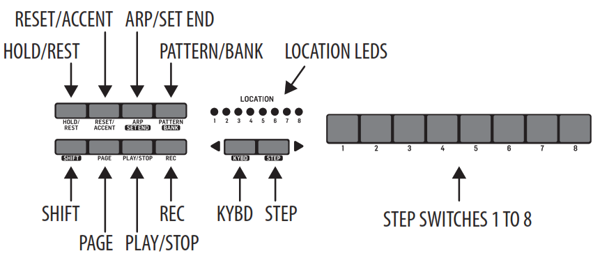 OVERVIEWThe following details show some of the basic operation of the sequencer. You can create a short pattern of 2 or 3 steps, before trying more complex patterns. Adjust a single parameter at a time, such as gate length, ratchet, accent, glide, rest, tie, or swing, and then listen to its effect during playback. It will help to choose a simple setting for the synthesizer, such as only one source, and no modulation of the VCO or VCF. The length of the step notes can be adjusted using the procedure shown on page 24. RECORDING A SIMPLE PATTERN 1. Press SHIFT and <KYBD to select the keyboard mode.2. Initialise the current pattern by pressing SHIFT, RESET, and PATTERN at the same time. This will delete any previous steps of the current pattern.3. Press REC, and the STEP 1 switch LED will begin flashing, indicating this is the current step about to be added and edited. (If you cannot select REC, then repeat step 1.)4. Press any note on the keyboard, or a rest as shown below.5. To enter a rest instead of a note, press the HOLD/REST switch. When a rest is added, the LOCATOR LED 8 will light.6. Press further notes. The next STEP switch LED will be flashing after each note or rest has been added.7. The gate length of a step can be adjusted using the TEMPO/GATE LENGTH control. The LOCATOR LEDs will turn red, showing the gate length from 1 to 8. If set to 8, this creates a tie with the next step. If the next step is the same note, this creates a longer note, as the 2 steps are tied.8. To create a “Ratchet,” hold SHIFT, and turn the GLIDE control. The locator LEDs will show the number of ratchets from 1 to 4, in yellow. For example, with a setting of 4, the single step is split into 4 equal parts. When a ratchet is applied, the LOCATION LED 6 will light.9. To turn the GLIDE on for a step, turn up the GLIDE control. To turn off, turn it all the way down. When GLIDE is on for a step, the LOCATION LED 5 will light.10. To increase the brightness or accent, press the RESET/ACCENT switch. When an accent is applied, the LOCATION LED 7 will light.11. Press REC when you have finished creating the pattern. It is not saved yet, but it can be played back. Caution: Do not turn off the unit, or create a new pattern, or the current unsaved pattern will be lost.PLAYING A PATTERN1. Press PLAY/STOP to listen to the current pattern.2. If you decide not to save it, you can repeat the recording steps above to record a new pattern. Alternatively, press PATTERN and RESET to recall the currently saved pattern, and discard any changes.3. If you decide to save the pattern, you must follow the “SAVING A PATTERN” procedure shown below, or it will not remain in memory if a new pattern is begun, or the power is turned off.4. To create a SWING for this pattern, hold SHIFT and adjust the TEMPO/GATE LENGTH control. In the center position, no swing is applied, if turned down, only the off-beats will play, and if all the way up, only the on-beats will play. The SWING setting for the pattern is saved when the pattern is saved as shown below.5. While playing a pattern: Press HOLD/REST to hold the current step. Press RESET/ACCENT to return to step 1. Press SHIFT and any STEP, and you can edit the gate length, rest, accent, ratchet, glide but not note. Press SHIFT and the same STEP again to exit step edit. (If playback is paused, the same operation can edit the note as well. Press PAGE to view the pattern page from 1 to 4. Press SHIFT and PAGE to return to automatic page-turning. Press SHIFT and ARP/SEND and a STEP to change the sequence end step. PLAY/STOP to pause playback.6. Press PLAY/STOP. SAVING A PATTERN1. Press and hold SHIFT + PLAY/STOP for 2 seconds until the LOCATOR LED of the current pattern number begins to flash green slowly.2. Press a STEP switch 1 to 8 to select the new desired pattern number.3. Press PATTERN + STEP switch 1 to 8 to select the desired bank number.4. Press SHIFT + REC to save the pattern and exit the save mode.RECALLING A SAVED PATTERN1. Press and hold PATTERN. The LOCATION LED will show the current pattern number. Use the <KYBD or STEP> switches to move up and down through the patterns 1 to 8, or press a STEP switch 1 to 8. You can also do this while a pattern is playing.2. Press and hold SHIFT and PATTERN. The LOCATION LED will show the current bank number. Use the <KYBD or STEP> switches to move up and down through the banks 1 to 8, or press a STEP switch 1 to 8. You can also do this while a pattern is playing. 3. Press PLAY/STOP to playback the current pattern.4. During playback, the LOCATION LEDs will show the current page of the pattern (1 to 4), and the STEP Switch LEDs will show thesteps moving.LIVE PERFORMANCEDuring playback, temporary adjustments can be made as follows. (None of these are saved with the pattern.)1. To add Ratchet to all steps of the pattern, press SHIFT and adjust the GLIDE control.2. To add SWING, press SHIFT and adjust the TEMPO control.3. To mute the pattern, press SHIFT + HOLD/ REST.4. To add an accent to all steps, press SHIFT + RESET/ACCENT.5. Use the TRANSPOSE switch to change the octave.EDITING A PATTERN1. To edit a pattern in Keyboard mode, press REC. The STEP switch LEDs will light.2. Press PAGE to select the pattern page from 1 to 4 to be edited. The green LOCATION LEDs 1 to 4 will show the current page.3. Press SHIFT and the STEP switch you want to edit. You can enter a new note, or a rest, and adjust any of the other parameters such as ratchet, glide on/off, and so on.4. Press SHIFT and the next STEP switch to be edited. (The steps will not automatically advance to the next step in line; you can choose which steps to edit next.)5. Press REC to exit the editing mode.6. Press PLAY/STOP to listen to the edited pattern.7. Remember to save the pattern using the “SAVING A PATTERN” procedure above.CREATING A PATTERN IN STEP MODE 1. Press SHIFT and STEP> to select the Sequencer’s STEP mode. The flashing LOCATION LED will turn from green (Keyboard mode) to yellow (Step mode).2. Initialise the current pattern by pressing SHIFT, RESET, and PATTERN at the same time. This will delete any previous steps of the current pattern. (If you want to use the current pattern instead, then do not initialise it.)3. Press PAGE to move to the desired page of your pattern. Then press SET END and a STEP switch to choose the length of the pattern. For example, if you are on page 1 and press SET END + 8, then the pattern length is 8 steps. If you press PAGE and reach page 4, and press SET END + 8, then the pattern will be 32 steps long (4 pages of 8 steps each).4. When the desired SET END is selected, all the STEP switch LEDs up to that step will be on solid red.5. Press SHIFT and any one of the STEP switches at the same time. It will begin to flash, indicating it is the current step about to be edited. You can now add a note, or rest, or any of the other functions described above in the Keyboard mode, such as Ratchet, Glide, Accent, change gate length and so on.6. Press SHIFT and the current STEP switch to finish editing that step. It will stop flashing.7. Repeat procedure steps 5 and 6 above, until all your required steps are good.8. Press PLAY/STOP to play the pattern.9. While playing, you can add temporary adjustments as shown in the “LIVE PERFORMANCE” procedure above. SAVING A PATTERN IN STEP MODE1. Patterns created in STEP mode are not saved in this mode.2. If you wanted to save it, first switch back to KEYBOARD mode by pressing SHIFT + <KYBD.3. Caution: Do not turn off the unit, or create a new pattern, or the current unsaved pattern will be lost.4. Save the pattern using the “SAVING A PATTERN” procedure shown above for the KEYBOARD mode.MS-1 MIDI Channel and Note Value
CHANGING THE MIDI CHANNELThe MIDI input and output channel may be changedusing the following procedure:1. Press SHIFT+ HOLD/REST + 8 to enter the setting mode. The LOCATION LED 1 will blink yellow.2. Press <KYBD or STEP> to select pages 1 or 2. The yellow LOCATION LED, shows the current page:3. Page 1 allows you to select the MIDI input channel, 1 to 16.4. Page 2 allows you to select the MIDI output channel, 1 to 16.5. Press STEP switches 1 to 8 to select numeric values from 1 to 8. The current value is indicated by a green LOCATION LED.6. To access values 9 to 16, press SHIFT + STEP switch 1 to 8. The current value is shown by a red LOCATION LED. Note: If a setting is on the same LED number as the current page LED, then the LED will flash alternately between the yellow page color and the green or red parameter color.7. Press SHIFT + HOLD/REST + 8 to exit the setting mode, and save any parameter changes.CHANGING THE SEQUENCER NOTE VALUEThe Note value used in the Sequencer may be changed using the following procedure:1. Press PLAY/STOP to play the current pattern.2. Press and hold the PATTERN/BANK switch and adjust the TEMPO control. Listen to the change in note value.3. The LOCATION LEDs will show the current note value in yellow, from 1 to 8 as follows:1: 1/1 note, 2: 1/2 note, 3: 1/2 note, 4: 1/4 note, 5: 1/4 note, 6: 1/8 note, ,7: 1/8 note, ,8: 1/16 note,4. Repeat this procedure at any time to change the note value.
ADSR EnvelopeThe stages of the ADSR envelope are shown in this simplified diagram below. The envelope can control the VCA level, the VCF cut-off frequency, and Pulse Width modulation of the VCO.

MS-1 SysEx informationSYSTEM EXCLUSIVE COMMANDSSome MS-1 parameters can be changed using MIDI system exclusive (SysEx) commands. A MIDI utility such as MIDI-OX can be used to send the SysEx command data string to the MS-1 using the USB MIDI connection between the computer and the MS-1.Please see the MS-1 section on our website for more details of the SysEx commands.
MS-1 MIDI
| Status | Second | Third | Parameter | Description | |
| Channel
Message |
8n | kk | vv | [0,7F] | Note Off |
| 9n | kk | vv | [0,7F] | Note On | |
| Bn | 5 | vv | [0,7F] | Glide Time | |
| Bn | 7B | — | [0,3FFF] | All Note Off | |
| En | bb | bb | Pitch Bend | ||
| SysRT | F8 | — | — | Timing Clock | |
| FA | — | — | Start | ||
| FB | — | — | Continue | ||
| FC | — | — | Stop |
MIDI ExamplesNote: (MIDI Input Channel 1)
| Function | Command |
| Note On | 90 3C 64 |
| Note Off | 80 3C 40 |
| Select glide time MIN | B0 05 00 |
| Select glide time MAX | B0 05 7F |
| All note off | B0 7B |
| Synthesizer Architecture | |
| Implementation | Analog |
| Keyboard | |
| Keys | 32 semi-weighted, full size keys |
| Keyboard sensing | Note on/off, velocity |
| VCO Section | |
| Knobs | Tune (±50 cent) |
| Range selector (16′, 8′, 4′, 2′) | |
| Faders | Modulation depth |
| Pulse width modulation (50% to minimum) | |
| Switches | PWM mode (LFO, manual, envelope) |
| Modulator Section | |
| Knobs | Waveform selector (triangular, square, random, noise) |
| Faders | LFO/CLK rate |
| Switches | LFO/CLK rate selector: low (0.1 Hz to 30 Hz), medium (0.2 Hz to 60 Hz), high (0.3 Hz to 120 Hz) |
| LED | Rate indicator |
| Source Mixer Section | |
| Faders | Pulse level |
| Sawtooth level | |
| Triangular level | |
| Sub oscillator level | |
| Noise level | |
| External audio level | |
| Switches | Sub oscillator waveform selector (1 octave down, 2 octave down, narrow 2 octave down) |
| VCF Section | |
| Faders | Cutoff frequency (10 Hz to 20 kHz) |
| Resonance (0 to self-oscillation) | |
| Envelope depth | |
| Modulation depth | |
| Keyboard follow (0 to 100%) | |
| Knobs | FM source selector (pulse, saw, sub osc 1 octave down, 2 octave down, narrow 2 octave down, noise) |
| FM depth | |
| VCA Section | |
| Switches | Envelope, gate selector |
| Envelope Section | |
| Faders | Attack time (2 ms to 4 s) |
| Decay time (2 ms to 10 s) Sustain level (0 to 100%)
|
|
| Release time (2 ms to 10 s) | |
| Switches | Gate-trigger selector (gate + trigger, gate, LFO) |
| Controllers Section | |
| Knobs | Volume |
| Glide time (0 to 5 s) | |
| Switches | Glide (on, off) |
| Transpose (low, medium, high) | |
| Faders | VCO bender sensitivity |
| VCF bender sensitivity | |
| LFO modulation | |
| Wheel/lever | Bender (with LFO MOD switch) |
| Handle Controls | LFO on/off switch |
| Bender thumbwheel (increase pitch only) | |
| Sequencer/Arpeggiator Section | |
| Steps | 32 steps maximum per pattern |
| Number of patterns | 64 patterns maximum |
| Memory storage | 8 banks with 8 patterns each |
| Switches | Hold/rest, reset/accent, arp/set end, pattern/bank, shift, page, play/stop, record, keyboard mode, step mode, steps 1-8 |
| Knob | |
| Connectivity | |
| DC Input Jack | 9 VDC, 600 mA |
| MIDI In/Out/Thru | 5-pin DIN / 16 channels |
| USB (MIDI) | USB 2.0, type B |
| Output | 1/4″ TS, max. +10 dBu |
| Headphones | 1/4″ TRS, max. +2 dBu @32 Ohm |
| External audio input | 1/4″ TS, max. +20 dBu |
| Footswitch (optional) | Sequencer hold (1/4″ TS) |
| 3.5 mm TS inputs | VCF control voltage (0 to 7 V) |
| External clock (+2.5 V or more) | |
| Control voltage (1 V/octave, 0 to 7 V) | |
| Gate (+2.5 V or more) | |
| 3.5 mm TS outputs | Control voltage (1V/octave, 0.417 to 5 V) |
| Gate (off= 0 V, on= 10 V) | |
| Velocity (0 to 5 V) | |
| 3.5 mm Handle connectors | Mod, grip |
| USB | |
| Type | Class-compliant USB 2.0, type B |
| Supported operating | Windows 7 or higher |
| systems | Mac OS X 10.6.8 or higher |
| Power Requirements | |
| External power adapter | 9 VDC, 1700 mA |
| Power consumption | |
| Environmental | 5.4 W maximum |
| Operating temperature | |
| range | 5°C – 40°C (41°F – 104°F) |
| Physical | |
| Dimensions (H x W x D) | 85 x 569 x 267 mm (3.4 x 22.4 x 10.5″) |
| Weight | 4.6 kg (10.1 lbs) |
| Shipping weight | 6.3 kg (13.9 lbs) |
Other important information1. Register online. Please register your new Music Tribe equipment right after you purchase it by visiting behringer.com. Registering your purchase using our simple online form helps us to process your repair claims more quickly and efficiently. Also, read the terms and conditions of our warranty, if applicable.2. Malfunction. Should your Music Tribe Authorized Reseller not be located in your vicinity, you may contact the Music Tribe Authorized Fulfiller for your country listed under “Support” at behringer.com. Should your country not be listed, please check if your problem can be dealt with by our “Online Support” which may also be found under “Support” at behringer.com. Alternatively, please submit an online warranty claim at behringer.com BEFORE returning the product.3. Power Connections. Before plugging the unit into a power socket, please make sure you are using the correct mains voltage for your particular model. Faulty fuses must be replaced with fuses of the same type and rating without exception.
FEDERAL COMMUNICATIONS COMMISSION COMPLIANCE INFORMATION Responsible Party Name: Music Tribe Commercial NV Inc.Address: 5270 Procyon Street, Las Vegas, NV 89118 USAPhone Number: +1 702 800 8290
MS-1complies with the FCC rules as mentioned in the following paragraph:This equipment has been tested and found to comply with the limits for a Class B digital device, pursuant to part 15 of the FCC Rules. These limits are designed to provide reasonable protection against harmful interference in a residential installation. This equipment generates, uses, and can radiate radio frequency energy and, if not installed and used in accordance with the instructions, may cause harmful interference to radio communications. However, there is no guarantee that interference will not occur in a particular installation. If this equipment does cause harmful interference to radio or television reception, which can be determined by turning the equipment off and on, the user is encouraged to try to correct the interference by one or more of the following measures:
- Reorient or relocate the receiving antenna
- Increase the separation between the equipment and receiver
- Connect the equipment into an outlet on a circuit different from that to which the receiver is connected
- Consult the dealer or an experienced radio/TV technician for helpThis device complies with Part 15 of the FCC rules. Operation is subject to the following two conditions:(1) this device may not cause harmful interference, and(2) this device must accept any interference received, including interference that may cause undesired operation.
Important information:Changes or modifications to the equipment not expressly approved by Music Tribe can void the user’s authority to use the equipment.
References
[xyz-ips snippet=”download-snippet”]