behringer EUROPOWER EP4000/EP2000 User Guide
Important Safety Instructions
![]() CAUTION: RISK OF ELECTRIC SHOCK!
CAUTION: RISK OF ELECTRIC SHOCK! ![]() DO NOT OPEN!
DO NOT OPEN!
![]() Terminals marked with this symbol carry electrical current of sufficient magnitude to constitute risk of electric shock.Use only high-quality professional speaker cables with ¼” TS or twist-locking plugs pre-installed. All other installation or modification should be performed only by qualified personnel.
Terminals marked with this symbol carry electrical current of sufficient magnitude to constitute risk of electric shock.Use only high-quality professional speaker cables with ¼” TS or twist-locking plugs pre-installed. All other installation or modification should be performed only by qualified personnel.![]() This symbol, wherever it appears, alerts you to the presence of uninsulated dangerous voltage inside the enclosure – voltage that may be sufficient to constitute a risk of shock.This symbol, wherever it appears, alerts you to important operating and maintenance instructions in the accompanying literature. Please read the manual.
This symbol, wherever it appears, alerts you to the presence of uninsulated dangerous voltage inside the enclosure – voltage that may be sufficient to constitute a risk of shock.This symbol, wherever it appears, alerts you to important operating and maintenance instructions in the accompanying literature. Please read the manual.![]() CautionTo reduce the risk of electric shock, do not remove the top cover (or the rear section).No user serviceable parts inside. Refer servicing to qualified personnel.
CautionTo reduce the risk of electric shock, do not remove the top cover (or the rear section).No user serviceable parts inside. Refer servicing to qualified personnel.![]() CautionTo reduce the risk of fire or electric shock, do not expose this appliance to rain and moisture. The apparatus shall not be exposed to dripping or splashing liquids and no objects filled with liquids, such as vases, shall be placed on the apparatus.
CautionTo reduce the risk of fire or electric shock, do not expose this appliance to rain and moisture. The apparatus shall not be exposed to dripping or splashing liquids and no objects filled with liquids, such as vases, shall be placed on the apparatus.![]() CautionThese service instructions are for use by qualified service personnel only. To reduce the risk of electric shock do not perform any servicing other than that contained in the operation instructions. Repairs have to be performed by qualified service personnel.
CautionThese service instructions are for use by qualified service personnel only. To reduce the risk of electric shock do not perform any servicing other than that contained in the operation instructions. Repairs have to be performed by qualified service personnel.
- Read these instructions.
- Keep these instructions.
- Heed all warnings.
- Follow all instructions.
- Do not use this apparatus near water.
- Clean only with dry cloth.
- Do not block any ventilation openings. Install in accordance with the manufacturer’s instructions.
- Do not install near any heat sources such as radiators, heat registers, stoves, or other apparatus (including amplifiers) that produce heat.
- Do not defeat the safety purpose of the polarized or grounding-type plug. A polarized plug has two blades with one wider than the other. A grounding-type plug has two blades and a third grounding prong. The wide blade or the third prong are provided for your safety. If the provided plug does not fit into your outlet, consult an electrician for replacement of the obsolete outlet.
- Protect the power cord from being walked on or pinched particularly at plugs, convenience receptacles, and the point where they exit from the apparatus.
- Use only attachments/accessories specified by the manufacturer.
 Use only with the cart, stand, tripod, bracket, or table specified by the manufacturer, or sold with the apparatus. When a cart is used, use caution when moving the cart/apparatus combination to avoid injury from tip-over.
- Unplug this apparatus during lightning storms or when unused for long periods of time.
- Refer all servicing to qualified service personnel. Servicing is required when the apparatus has been damaged in any way, such as power supply cord or plug is damaged, liquid has been spilled or objects have fallen into the apparatus, the apparatus has been exposed to rain or moisture, does not operate normally, or has been dropped.
- The apparatus shall be connected to a MAINS socket outlet with a protective earthing connection.
- Where the MAINS plug or an appliance coupler is used as the disconnect device, the disconnect device shall remain readily operable.
- Correct disposal of this product: This symbol indicates that this product must not be disposed of with household waste, according to the WEEE Directive (2012/19/EU) and your national law. This product should be taken to a collection center licensed for the recycling of waste electrical and electronic equipment (EEE). The mishandling of this type of waste could have a possible negative impact on the environment and human health due to potentially hazardous substances that are generally associated with EEE. At the same time, your cooperation in the correct disposal of this product will contribute to the efficient use of natural resources. For more information about where you can take your waste equipment for recycling, please contact your local city office, or your household waste collection service.
- Do not install in a confined space, such as a book case or similar unit.
- Do not place naked flame sources, such as lighted candles, on the apparatus.
- Please keep the environmental aspects of battery disposal in mind. Batteries must be disposed-of at a battery collection point.
- This apparatus may be used in tropical and moderate climates up to 45°C.
 Use only with the cart, stand, tripod, bracket, or table specified by the manufacturer, or sold with the apparatus. When a cart is used, use caution when moving the cart/apparatus combination to avoid injury from tip-over.
 Correct disposal of this product: This symbol indicates that this product must not be disposed of with household waste, according to the WEEE Directive (2012/19/EU) and your national law. This product should be taken to a collection center licensed for the recycling of waste electrical and electronic equipment (EEE). The mishandling of this type of waste could have a possible negative impact on the environment and human health due to potentially hazardous substances that are generally associated with EEE. At the same time, your cooperation in the correct disposal of this product will contribute to the efficient use of natural resources. For more information about where you can take your waste equipment for recycling, please contact your local city office, or your household waste collection service.
EUROPOWER EP4000/EP2000 Hook-up
Step 1: Hook-Up


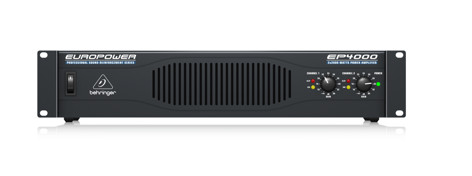
Step 2: Controls
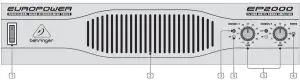
Since control elements of both the EP2000 and the EP4000 are identical, we have used the EP2000 as the model represented in the illustrations to assure simplicity.
- The main switch is used to power up the amp.
- Merely switching the unit off does not mean that it is fully disconnected from the mains. When not using the unit for prolonged periods of time, please unplug the unit’s power cord from the power outlet.
- Ventilation openings are located at the front of the unit, so that hot air is prevented from being trapped inside the unit, thus causing faulty operation or even damage.
- The CLIP LED lights up when the signal is distorted. Should distortion occur, reduce the input level, so that the CLIP LED stops lighting up.
- The SIGNAL LED lights up as long as a signal is present at the input.
- The Gain control (channels 1 and 2) is used for setting up the input gain.
- The POWER LED lights up as soon as the unit is powered up.
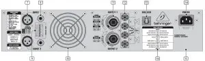
- These are the balanced XLR inputs (channels 1 and 2).
- These are the stereo ¼” TRS inputs (channels 1 and 2). They can also be used with unbalanced plugs.
- These are the MODE switches, used to alter the operating modes as well as to set the limiters and high-pass filters.
- The unit’s fan is located here. Fan speed adjusts automatically to assure trouble-free operation.
- To prevent faulty operation, please assure that the unit is kept at a distance from other appliances emanating heat.
- These are the speaker outputs (channels 1 and 2). When running the unit in mono bridged mode, please use the channel 1 output exclusively.
- These are the output terminals (channels 1 and 2). When running in mono, please make sure to use both middle connectors to connect your loudspeaker.
- BREAKER (automated fuse). After eliminating the cause of faulty operation, simply depress the BREAKER and power up the unit again.The BREAKER acts in place of common discardable fuses. Caution
- Before engaging the BREAKER switch, you should power down the unit (POWER switch set to OFF)!
- Power is supplied via an IEC connector.The matching cable is provided with the unit.
- SERIAL NUMBER of your EUROPOWER.
- Here you can find a detailed overview of the individual MODE SWITCHES functions (9).
When running in mono-bridged mode, the voltage of both channels is added up and fed into a single loudspeaker system. There is one input and one output signal respectively, and only the controls of channel 1 (and not of channel 2) are used.
- However, should the DIP switches 4 and 5 still be in PARALLEL INPUTS position while in mono-bridged mode, the signal on the free input (input channel 2) can be forwarded to an additional amp.
Examples:
- Driving a single 8-Ohm loudspeaker.
- Driving a single 4-Ohm loudspeaker
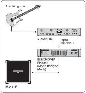 Mono-bridged mode
When the amp is overdriven for longer periods of time, the output signal may occasionally be muted for several seconds. In certain situations, excessive overdriving may trigger off the automated fuse. To avoid overdriving the amp, please continually make sure that an appropriate volume level is applied.
![]() Caution
Caution
- 2-Ohm loads should never be applied when in mono-bridged mode.
- When connecting a balanced input signal, please make sure to exclusively use balanced cables for passing the signal further on. Otherwise, a single unbalanced cable can turn the entire signal unbalanced.
Safety precautions for mono-bridged operation
- Running your amp in mono-bridged mode can quickly result in excessive overdriving and premature shutting down of the unit itself. In the worst-case scenario, your loudspeakers may be damaged permanently. Therefore, you should always make sure that the speakers you use can indeed handle the power load fed into them.
- A voltage of up to 100 V RMS is present between the output connectors of the EP4000. Always implement appropriate safety precautions when connecting your speakers to avoid the risk of electric shock.
Step 3: Getting started
InputsEach channel features balanced XLR and ¼” TRS stereo jack inputs, with input impedances of 20 kΩ (balanced) and 10 kΩ (unbalanced).In general, balanced signals cause less noise than unbalanced signals.For balanced input signals, use the XLR and ¼” TRS stereo inputs. For unbalanced input signals, use the unused pin of the XLR connector with grounding.No alteration is necessary on mono jack connectors.
OutputsYour EUROPOWER offers several output connection possibilities: two professional speaker connectors and two pairs of touch-safe binding posts.The professional speaker connectors were especially developed for driving high-power speakers.They snap in securely, prevent electric shock and assure correct polarity. The upper connector drives either one or both channels, and is therefore well-suited for mono-bridged operation (1+/2+).The lower connector carries the signals from channel 2 only.
Using the binding posts
To connect the loudspeakers to the amplifier’s binding posts, please do the following:
- Switch off the amp and disconnect it from the mains (unplug mains connector).
- Remove the protective plastic covers shielding the binding posts by loosening the two screws on the right-hand side of the connections and lift the plastic cover upwards.
- Attach the terminal of your loudspeaker cable to the corresponding binding post.
- Place the protective plastic covers into its original upright position on each binding post and replace the two screws.
Specifications
| Output Power | |
| RMS @ 1% THD (Sine Wave), Both Channels Driven | |
| EP4000 | |
| 8 Ω per channel | 550 W |
| 4 Ω per channel | 950 W |
| 2 Ω per channel | 1250 W |
| EP2000 | |
| 8 Ω per channel | 350 W |
| 4 Ω per channel | 500 W |
| 2 Ω per channel | 650 W |
| RMS @ 1% THD (Sine Wave), Bridged Mode | |
| EP4000 | |
| 8 Ω | 1750 W |
| 4 Ω | 2400 W |
| EP2000 | |
| 8 Ω | 1000 W |
| 4 Ω | 1300 W |
| Peak Power, Both Channels Driven | |
| EP4000 | |
| 8 Ω per channel | 750 W |
| 4 Ω per channel | 1400 W |
| 2 Ω per channel | 2000 W |
| EP2000 | |
| 8 Ω per channel | 400 W |
| 4 Ω per channel | 700 W |
| 2 Ω per channel | 1000 W |
| Peak Power, Bridged Mode | |
| EP4000 | |
| 8 Ω | 2800 W |
| 4 Ω | 4000 W |
| EP2000 | |
| 8 Ω | 1500 W |
| 4 Ω | 2000 W |
| Distortion | |
| EP4000 | < 0.02% |
| EP2000 | < 0.01% |
| Frequency Response | |
| at 10 dB below rated output power | 20 Hz – 20 kHz, +0/-1dB |
| at -3 dB points | 5 Hz – 50 kHz |
| Damping Factor | |
| EP4000/EP2000 | > 300 @ 8 Ω |
| Noise | |
| unweighted, 20 Hz to 20 kHz | -100 dB |
| Voltage Gain | |
| EP4000 | 50x (34 dB) |
| EP2000 | 40x (32 dB) |
| Input Sensitivity | |
| V RMS (@ 8 Ω) | EP4000 1.23 V (+4.0 dBu)EP2000 1.15 V (+3.4 dBu |
| Input Impedance | |
| EP4000/EP2000 | 10 k Ω unbalanced, 20 k Ω balanced |
| Controls | |
| Front | Power switch, gain control (channels 1 and 2) |
| Rear | DIP switches (10x) |
| Indicators | |
| POWER | green LED |
| CLIP | red LED, 1 per channel |
| SIGAL | yellow LED, 1 per channel |
| Connectors | |
| Inputs | Balanced XLR and ¼” TRS connectors |
| Outputs | Touch-Proof binding posts and professional speaker connectors |
| Cooling | |
| EP4000/EP2000 | Continuously variable speed fan, back-tofront air flow |
| Amplifier Protection | |
| EP4000/EP2000 | Full short circuit, open circuit, thermal and HF protection Stable into reactive or mismatched loads |
| Load Protection | |
| EP4000/EP2000 | Turn-on/off muting, AC coupling |
| Output Circuit Type | |
| EP4000 | Class H complementary linear output |
| EP2000 | Class AB complementary linear output |
| Power Supply | |
| Mains Voltage/Breaker | |
| 100 – 120 V~, 50/60 Hz | 15 A |
| 220 – 230 V~, 50/60 Hz | 8 A |
| Power Consumption | |
| EP4000 | max. 2600W |
| EP2000 | max. 1700 W |
| Mains connector | Standard IEC receptacle |
| Dimensions/Weight | |
| Dimensions (H x W x D) | |
| EP4000/EP2000 | approx. 90 x 483 x 405 mm(approx. 3.5 x 19 x 15.9″) |
| Weight | |
| EP4000 | 17.4 kg (approx. 38.3 lbs) |
| EP2000 | 15.7 kg (approx. 34.6 lbs) |
Other important information
Important information
- Register online. Please register your new MusicTribe equipment right after you purchase it by visiting musictribe.com. Registering your purchase using our simple online form helps us to process your repair claims more quickly and efficiently. Also, read the terms and conditions of our warranty, if applicable.
- Malfunction. Should your MusicTribe Authorized Reseller not be located in your vicinity, you may contact the MusicTribe Authorized Fulfiller for your country listed under “Support” at musictribe.com. Should your country not be listed, please check if your problem can be dealt with by our “Online Support” which may also be found under “Support” at musictribe.com. Alternatively, please submit an online warranty claim at musictribe.com BEFORE returning the product.
- Power Connections. Before plugging the unit into a power socket, please make sure you are using the correct mains voltage for your particular model. Faulty fuses must be replaced with fuses of the same type and rating without exception.
LEGAL DISCLAIMER
Music Tribe accepts no liability for any loss which may be suffered by any person who relies either wholly or in part upon any description, photograph, or statement contained herein. Technical specifications, appearances and other information are subject to change without notice. All trademarks are the property of their respective owners. Midas, Klark Teknik, Lab Gruppen, Lake, Tannoy, Turbosound, TC Electronic, TC Helicon, Behringer, Bugera, Oberheim, Auratoneand Coolaudio are trademarks or registered trademarks of Music Tribe Global Brands Ltd. © Music Tribe Global Brands Ltd. 2021 All rights reserved.
LIMITED WARRANTY
For the applicable warranty terms and conditions and additional information regarding Music Tribe’s Limited Warranty, please see complete details online at musictribe.com/warranty.
 report this ad
[xyz-ips snippet=”download-snippet”]