![]()
Quick Start Guide
![]()
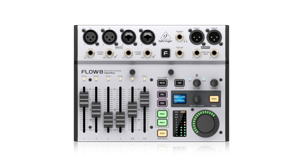
FLOW 88-Input Digital Mixer with Bluetooth Audio and App Control,60 mm Channel Faders, 2 FX Processors, and USB/Audio Interface
Important Safety Instructions
![]()
 Terminals marked with this symbol carry an electrical current of sufficient magnitude to constitute risk of electric shock. Use only high-quality professional speaker cables with ¼” TS or twist-locking plugs pre-installed. All other installation or modifications should be performed only by qualified personnel.This symbol, wherever it appears, alerts you to the presence of uninsulated dangerous voltage inside the enclosure – voltage that may be sufficient to constitute a risk of shock.
 This symbol, wherever it appears, alerts you to important operating and maintenance instructions in the accompanying literature. Please read the manual.CautionTo reduce the risk of electric shock, do not remove the top cover (or the rear section). No user-serviceable parts inside. Refer servicing to qualified personnel.CautionTo reduce the risk of fire or electric shock, do not expose this appliance to rain and moisture. The apparatus shall not be exposed to dripping or splashing liquids and no objects filled with liquids, such as vases, shall be placed on the apparatus.CautionThese service instructions are for use by qualified service personnel only. To reduce the risk of electric shock do not perform any servicing other than that contained in the operation instructions.Repairs have to be performed by qualified service personnel.
- Read these instructions.
- Keep these instructions.
- Heed all warnings.
- Follow all instructions.
- Do not use this apparatus near water.
- Clean only with a dry cloth.
- Do not block any ventilation openings. Install in accordance with the manufacturer’s instructions.
- Do not install near any heat sources such as radiators, heat registers, stoves, or other apparatus (including amplifiers) that produce heat.
- Do not defeat the safety purpose of the polarized or grounding-type plug. A polarized plug has two blades with one wider than the other. A grounding-type plug has two blades and a third grounding prong. The wide blade or the third prong are provided for your safety. If the provided plug does not fit into your outlet, consult an electrician for the replacement of the obsolete outlet.
- Protect the power cord from being walked on or pinched particularly at plugs, convenience receptacles, and the point where they exit from the apparatus.
- Use only attachments/accessories specified by the manufacturer.

- Use only with the cart, stand, tripod, bracket, or table specified by the manufacturer, or sold with the apparatus. When a cart is used, use caution when moving the cart/apparatus combination to avoid injury from tip-over.
- Unplug this apparatus during lightning storms or when unused for long periods of time.
- Refer all servicing to qualified service personnel. Servicing is required when the apparatus has been damaged in any way, such as power supply cord or plug is damaged, liquid has been spilled or objects have fallen into the apparatus, the apparatus has been exposed to rain or moisture, does not operate normally, or has been dropped.
- The apparatus shall be connected to a MAINS socket outlet with a protective earthing connection.
- . Where the MAINS plug or an appliance coupler is used as the disconnect device, the disconnect device shall remain readily operable.
- Correct disposal of this product: This symbol indicates that this product must not be disposed of with household waste, according to the WEEE Directive (2012/19/EU) and your national law. This product should be taken to a collection center licensed for the recycling of waste electrical and electronic equipment (EEE).The mishandling of this type of waste could have a possible negative impact on the environment and human health due to potentially hazardous substances that are generally associated with EEE. At the same time, your cooperation in the correct disposal of this product will contribute to the efficient use of natural resources. For more information about where you can take your waste equipment for recycling, please contact your local city office or your household waste collection service.
- Do not install in a confined space, such as a bookcase or similar unit.
- Do not place naked flame sources, such as lighted candles, on the apparatus.
- Please keep the environmental aspects of battery disposal in mind. Batteries must be disposed of at a battery collection point.
- This apparatus may be used in tropical and moderate climates up to 45°C.
LEGAL DISCLAIMER
Music Tribe accepts no liability for any loss which may be suffered by any person who relies either wholly on or in part upon any description, photograph, or statement contained herein. Technical specifications, appearances and other information are subject to change without notice.All trademarks are the property of their respective owners. Midas, Klark Teknik, Lab Gruppen, Lake, Tannoy, Turbosound, TC Electronic, TC Helicon, Behringer, Bugera,Auratone and Coolaudio are trademarks or registered trademarks of Music Tribe Global Brands Ltd. © Music Tribe Global Brands Ltd. 2020 All rights reserved.
LIMITED WARRANTY
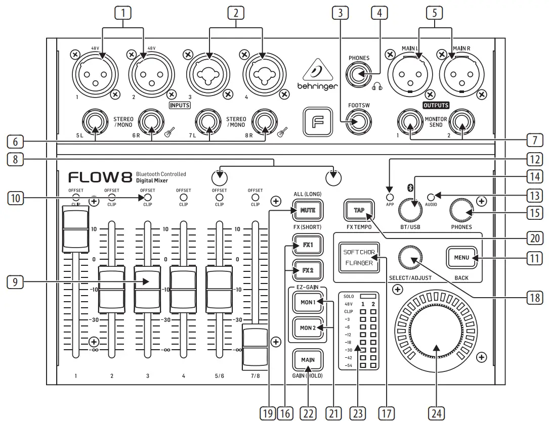
For the applicable warranty terms and conditions and additional information regarding Music Tribe’s Limited Warranty, please see complete details online at musictribe.com/warranty.FLOW 8 Controls Step 2: Controls
 |
|
- MIC 1/MIC 2 inputs accept audio signals over cables using balanced XLR connectors. Both XLR jacks feature individually selectable phantom power for condenser mics.Phantom power can be activated in the control app or via the MAIN button and SELECT/ADJUST push encoder (see “Getting Started”).
- MIC 3/MIC 4 combo jacks accept audio signals from line-level sources or dynamic microphones over cables with balanced XLR, balanced ¼” TRS or unbalanced ¼” TS connectors. To run condenser microphones with these inputs, you will need an external preamp or phantom power supply that provides +48 V of power, such as the Behringer PS400.NOTE: These inputs do NOT offer phantom power!
- FOOTSW jack connects to an external single or dual control footswitch using a ¼” TRS connector.
- PHONES jack connects to headphones using a ¼” TRS stereo plug.
- MAIN L/MAIN R connections send out the final stereo mix over cables using balanced XLR connectors.
- STEREO/MONO inputs can accept either stereo line-level signals (5/6 and 7/8 stereo pairs), or a mono signal (5L and 7L for mono line-level sources, 6R and 8R formono Hi-Z signals from guitars and basses.)
- MONITOR SEND (MON 1/MON 2) jacks provide two monitor outputs. These outputs accept cables with balanced ¼” TRS or unbalanced ¼” TS connectors.
- HOLDING POSTS allow you to place your smartphone directly onto the mixer for easy viewing of levels and settings on the smartphone control app.
- CHANNEL FADERS set mix levels for their respective channels. These faders can also be used to control the send levels to the MON 1/MON 2 output jacks or the FX 1/FX 2 internal busses when selected in the control app or by pressing the menu layer’s related hardware button (see [16], [21] and [22]).
- OFFSET/CLIP LEDs indicate when the input gain is clipping the channel headroom or when the hardware faders are in a different position than the fader level shown in the control app (the LEDs will switch off when the hardware faders are returned to the level shown in the control app).
- MENU button push opens Menu Mode when the MAIN, MON 1, or MON 2 menu layer is selected.Pressing the MENU button again will exit from Menu Mode.
- APP LED starts blinking when Bluetooth* pairing is underway for the control app. When pairing is successful, the LED lights consistently. When the Bluetooth connection fails or is deactivated, the LED will go off. See the Bluetooth instructions in “Getting Started” for details.
- AUDIO LED lights up to indicate when Bluetooth pairing is active for audio streaming. See the Bluetooth instructions in “Getting Started” for details.
- BT/USB knob sets the volume for digital audio routed into the mixer via Bluetooth or the rear USB AUDIO connector.
- PHONES knob controls the headphone volume.
- FX 1/FX 2 buttons switch between the two FX engines for patch selection and parameter adjustment. When the FX 1 or FX 2 menu buttons are selected, the channel faders are then used to set Send levels to the FX engines.
- MENU SCREEN displays the names of the currently active effects for the two FX engines and allows access to the FX preset list when the FX 1 or FX 2 button is pressed. Press the MENU button to open and close Menu Mode. Rotate the SELECT/ADJUST push encoder to navigate sub-menus and then press to select specific menu items.
- SELECT/ADJUST push encoder is used to navigate menus (turn) and to enter/confirm (press).
- MUTE button switches off all audio from the FX section. A long press of the MUTE button activates the ALL MUTE function (see “Getting Started”).
- TAP button allows you to tap in a tempo for quick adjustment of time-based effects.
- MON 1/MON 2 buttons select either of the monitor mixes for direct monitoring and level setting in place of the main mix.To return to the main mix, press the MAIN button.Press MON 1 and MON 2 simultaneously to active the EZ GAIN function (see “Getting Started”).
- MAIN button selects the main mix for the final output. Press the MAIN button to return to the main mix after selecting and checking monitor mixes with the MON 1 andMON 2 buttons. Press and hold the MAIN button for manual gain setting and to activate phantom power (see “Getting Started”).
- VU METER shows levels for the main mix, monitor mixes or FX send signals. In SOLO mode, this meter allows a more detailed gain setting on individual input channels. The red LEDs “1” and “2” at the top of the meter will light up when +48 V phantom power is activated for Channels 1 and 2 respectively.
- MAIN knob controls the master volume for the currently selected bus – FX 1, FX 2, MON 1, MON 2, or MAIN. The final volume setting is indicated by the LED ring around the knob. When adjusting the master volume setting of the currently-selected bus from the smartphone app, the LED ring will change to show the volume setting selected for that bus in the app.
- USB AUDIO jack enables connection to a computer for audio streaming, firmware updates, and MIDI control. This USB connection also allows FLOW 8 to be used asa multi-channel audio interface for recording to a computer. When used as a recording interface, 10 channels are transmitted to the computer (8 analog inputs, plus the mainL/R bus mix tapped pre-fader), and 2 stereo playback channels, controllable via the BT/ USB channel, are streamed back to the FLOW 8 mixer.
- DC IN jack uses a Micro-USB connection to provide power to the unit. Power should come from either the included external power supply or a USB power bank witha Micro-USB connection.
*The Bluetooth word mark and logos are registered trademarks owned by Bluetooth SIG, Inc., and any use of such marks is under license.
FLOW 8 Getting Started
Step 3: Getting started
Bluetooth Connection: Streaming and ControlTo stream audio from a Bluetooth-enabled device, you will need a smartphone, tablet or computer with basic Bluetooth audio connectivity.

The mixer can only be controlled and edited by Android** or Apple iOS** control app. Only one Bluetooth device at a time may be used to control the mixer via the control app.Audio may be streamed from a separate Bluetooth device or from the same device running the control app, but a maximum of one audio device and one device with the control app are allowed at the same time.NOTE: FLOW 8 uses two types of Bluetooth simultaneously: Bluetooth Low Energy (BLE) for the control app and regular Bluetooth Audio for wireless audio streaming.Bluetooth pairing for a control appTo control FLOW 8 via an app from your Bluetooth device, use the following procedure:
- Download and install the free FLOW control app from the Apple Store** or Google Play Store**.
- Enable Bluetooth on your smartphone or tablet.
- Press the MENU button on the FLOW 8 mixer hardware and select the BT PAIRING menu by turning the SELECT/ADJUST push encoder. Press the encoder to enter this sub-menu.
- Select PAIR APP with the SELECT/ADJUST push encoder, and then press the encoder to start the search for a Bluetooth device.
- Start the FLOW control app on your Bluetooth device (within 60 seconds). The control app will automatically detect FLOW 8 and connect. When connected, the Bluetooth icon in the control app will change color from gray (inactive) to blue (active), and the blue APP LED on the mixer hardware will light consistently.
- In case of an unsuccessful connection, press the RETRY button on the app and follow the on-screen instructions.
**Android and Google Play Store are trademarks of Google, Inc. Apple iOS and Apple Store are trademarks of Apple Inc.Bluetooth pairing for audio streamingTo stream audio to your FLOW 8 mixer from your Bluetooth device, use the following procedure:
- Enable Bluetooth on your smartphone or tablet (if not already done).
- Press the MENU button on the FLOW 8 mixer hardware and select the BT PAIRING menu by turning the SELECT/ADJUST push encoder. Press the encoder to enter this sub-menu.
- Select PAIR AUDIO with the SELECT/ADJUST push encoder, and then press the encoder to start the search for a Bluetooth device.
- Go to the Bluetooth menu of your smartphone or tablet.
- Select “FLOW 8 (Audio)” on your smartphone or tablet to pair.NOTE: The specific device-naming format that appears in the Bluetooth menu of your smartphone/tablet may vary by brand, as well as by OS version.
- When pairing is successful, the menu on your smartphone or tablet will indicate success, and the blue AUDIO LED on the mixer hardware will light consistently.
- Begin audio playback on your smartphone or tablet (e.g., a radio app or media player app). Audio will stream wirelessly in stereo to your FLOW 8 mixer.
- Make final level adjustments. You can adjust the Bluetooth playback level by four different means:
- Level up/down hardware buttons on your smartphone or tablet
- Level control inside your audio playback app
- BT/USB level knob on the FLOW 8 mixer hardware
- Inside the FLOW control app at the BT/USB stereo channel on the mixer view
NOTE: Some smartphone or tablet apps, such as YouTube*, will stop audio playback when you change screens (e.g., switching to the FLOW control app screen). To stream audio without interruption, we recommend you use a “pure” audio app.*YouTube is a trademark of Google Inc.
Footswitch operationBy using a footswitch with the FOOT SW jack, you can mute effects, tap in a tempo for time-based effects, or select next or previous snapshot:
- Footswitch Mode “FX” (default mode): Switch 1 = MUTE (both FX engines), Switch 2 = TAP TEMPO (both FX engines)
- Footswitch Mode “SNAPSHOT”: Switch 1 = Snapshot Up (next), Switch 2 = Snapshot Down (previous)
FX Menu Navigation
- When the FX 1 or FX 2 menu layer is selected on the mixer hardware, you will see the currently selected effect preset.This preset can be changed by turning and pressing the SELECT/ADJUST push encoder.
- Pressing the MENU button while in the FX 1 or FX 2 layer opens the editable parameters (two per effect) for adjustment.◊ Turning the SELECT/ADJUST push encoder allows you to change the value of the upper/first parameter.◊ Pressing the SELECT/ADJUST push encoder accesses the lower/second parameter, which will allow you to toggle between 2 possible values/states.
- Pressing the MENU button again will return you to the preset select page.
ALL MUTE FunctionThe ALL MUTE function mutes all channels 1-8, as well as the Bluetooth channel.To activate ALL MUTE, press and hold the MUTE button.When ALL MUTE is active, you will see these indicators:
- The MENU SCREEN will light red.
- The OFFSET/CLIP LEDs will blink.
- The two red “1” and “2” LEDs at the top of the VU METER will blink.
To exit ALL MUTE, short press the MUTE button.This ALL MUTE mode is perfect for quick and easy connection/ disconnection of cables while avoiding pops and clicks that could damage connected speakers and headphones.
Manual gain change and phantom powerTo manually adjust gain for an input channel or activate phantom power (channels 1 and 2 only):
- Press and hold the MAIN button. The MENU SCREEN displaywill turn yellow-green.
- Move a slider to select the desired channel.
- Use the slider to set the gain.
- Press the SELECT/ADJUST push encoder to select/deselect+48 V phantom power for channels 1 or 2.
- Release the MAIN button to exit.
EZ GAIN functionThe EZ GAIN function will automatically calibrate and set the gain and channel level. For Channels 1 and 2, the +48 V phantom power will be automatically selected, when required. To activate the EZ GAIN function:
- Press the MON 1 and MON 2 buttons simultaneously. The MENU SCREEN display will turn green.
- Turn the SELECT/ADJUST push encoder to select an input for EZ GAIN calibration. When selecting ALL, the mixer will calibrate all 8 input channels simultaneously.
- Press the SELECT/ADJUST push encoder to start the calibration.
- Sing/speak/play through the channel, and the mixer will auto-calibrate the gain and channel level, and switch on +48 V phantom power when required.NOTE: Please run the calibration process for a minimum of 7 to 10 seconds for best results!
- When you stop performing, press the SELECT/ADJUST push encoder to finish the calibration.
- To calibrate additional channels, repeat Steps 2-5.
- When done, you can exit EZ GAIN mode by pressing the MAIN button or any of the other bus buttons.
MIDI Implementation
OVERVIEW
|
Input Channels Section |
MIDI Ch. |
| Input Ch. 1 | 1 |
| Input Ch. 2 | 2 |
| Input Ch. 3 | 3 |
| Input Ch. 4 | 4 |
| Input Ch. 5/6 | 5 |
| Input Ch. 7/8 | 6 |
| Input Ch. USB/BT | 7 |
| MAIN BUS | 8 |
| MON1 BUS | 9 |
| MON2 BUS | 10 |
| FX 1 BUS | 11 |
| FX 2 BUS | 12 |
| FX-Slots Section | MIDI Ch. |
| FX 1 | 14 |
| FX 2 | 15 |
| Global Control Section | MIDI Ch. |
| SNAPSHOTS – whole mixer | 16 |
| FX 1 / FX 2 – common ctrl. | “ |
| [MIDI-Ch. 13 = not used] |
INPUT CHANNELS
| Section | MIDI Ch. | Command | Min. Value | Max.Value | Parameter | Min. Value | Max. Value | Notes | Comment |
| Input Ch. 1 | 1 | CC 7 | 0,1 | 127 | Channel LEVEL(to MAIN) | OFF, -70 dB | +10 dB | Value 0 = OFF, Value 1-127 = the actual level control from -70 to +10 dB | |
| “ | CC 10 | 0 | 127 | Channel BALANCE (to | 1.0 LEFT | 1.0 RIGHT | Value 64 = “0.0 CENTER” | ||
| “ | “ | CC 5 | 0 | 1-127 | MUTE 1 | NO MUTE | MUTE | Switch; value 0 = “MUTE OFF”; value 1-127 = “MUTE” | |
| “ | “ | CC 6 | 0 | 1-127 | SOLO | NO SOLO | SOLO | Switch; value 0 = “SOLO OFF”; value 1-127 = “SOLO” | |
| “ | “ | CC 1 | 0 | 127 | EQ LOW | -15 dB | +15 dB | Continuous control., value 64 = “0.0 dB” (center postion) | |
| “ | “ | CC 2 | EQ LOW MID | “ | “ | ||||
| “ | CC 3 | EQ HI MID | “ | “ | “ | ||||
| .. | CC 4 | EQ HI | “ | “ | “ | ||||
| “ | “ | CC 8 | 0 | 127 | GAIN | -20 dB | +60 dB | NOT on Ch. USB/BT | Continuous control |
| CC 9 | 0 | 127 | LOW CUT | 20 Hz | 600 Hz | NOT on Ch. USB/BT | Continuous control | ||
| “ | CC 11 | 0 | 100-127 | COMP | 0% | 100% | NOT on Ch. USB/BT | Continuous control; values 101-127 = identical to max.value = 100% | |
| “ | CC 12 | 0 | 1-127 | 48V | OFF | ON | ONLY on Ch. 1 + 2 | Switch; value 0 = “48V OFF”; value 1-127 = “48V ON” | |
| “ | CC 14 | 0,1 | 127 | SEND LEVEL toMOM | OFF, -70 dB | +10dB | Value 0 = OFF, Value 1-127 = the actual level controlfrom -70 to +10 dB | ||
| “ | “ | CC 15 | 0,1 | 127 | SEND LEVEL toMON2 | OFF, -70 dB | +10dB | “ | |
| “ | “ | CC 16 | 0,1 | 127 | SEND LEVEL to FX 1 | OFF, -70 dB | +10dB | “ | |
| “ | “ | CC 17 | 0,1 | 127 | SEND LEVEL to FX 2 | OFF, -70 dB | +10dB | “ |
>Each Input Channel is assigned to one specific MIDI-Channel.
BUSSES
| Section | MIDICh. | Command | Min. Value | Max. Value | Parameter | Min. Value | Max. Value | Notes | Comment |
| MAIN BUS | 8 | CC 7 | 0,1 | 127 | BUS LEVEL | OFF, -70 dB | Value 0 = OFF, Value 1-127 = the actual level control from -70 to +10 dB | ||
| “ | “ | CC 10 | 0 | 127 | BUS BALANCE | 1.0 LEFT | 1.0 RIGHT | ONLY on MAIN BUS | Value 64 = “0.0 CENTER” |
| “ | CC 8 | 0 | 127 | BUS LIMITER | -30 dB | 0 dB | NOT on FX 1/2 BUS | Continuous control | |
| “ | “ | CC 11 | 0 | 127 | 9-BAND EQ 62 Hz | -15 dB | +15 dB | NOT on FX 1/2 BUS | Continuous control; value 64 = “0.0dB”(center postion) |
| “ | “ | CC 12 | “ | ‘ | 9-BAND EQ 125 Hz | “ | |||
| “ | CC 13 | “ | 9-BAND EQ 250 Hz | “ | “ | ||||
| “ | “ | CC 14 | “ | 9-BAND EQ 500 Hz | “ | “ | |||
| “ | “ | CC 15 | “ | 9-BAND EQ 1 kHz | “ | “ | |||
| “ | “ | CC 16 | “ | 9-BAND EQ 2 kHz | “ | “ | |||
| “ | “ | CC 17 | “ | 9-BAND EQ 4 kHz | “ | “ | |||
| “ | “ | CC 18 | 9-BAND EQ 8 kHz | “ | “ | ||||
| “ | “ | CC 19 | 9-BAND EQ 16 kHz | ‘ | “ |
>Each BUS is assigned to one specific MIDI-Channel.
FX CONTROL
| Section | MIDICh. | Command | Min.Value | Max.Value | Parameter | Min. Value Max. Value | Notes | Comment |
| FX 1 I FX 2 | 14 / 15 | Prog. Chg. | 1 | 16 | EFFECT PRESET | Program Change 0 & 17-127 = ignored | ||
| 1 | 16 | |||||||
| CC 1 | 0 | 100-127 | PARAMETER 1 | 0% | 10090 | Continuous control; values 101-127 = identical tomax. value = 100% | ||
| CC 2 | 0 | 1-127 | PARAMETER 2 | Value A | Value B | Switch; MIDI value 0 = “Value A”; MIDI value 1-127 = “Value B” |
GLOBAL CONTROL
|
Section |
MIDI Ch. | Command | Min. | Max. Value | Parameter | Min. Value | Max. Value | Notes |
Comment |
| SNAPSHOT | 16 | Prog. Chg. | Value | 16 | Load MIXERSNAPSHOT | 1 | 16 | Loading #16 = RESET! | Program Change 0 & 17-127 = ignored; Presets = 1-15; RESET = Prog. Chg. #16 |
| FX 1 / FX 2 | “ | CC 1 | 1 | 1-127 | FX MUTE | NO MUTE | MUTE | Mutes BOTH FX Sends | Switch; value 0 = “MUTE OFF”; value 1-127 = “MUTE” |
| FX 1 / FX 2 | “ | Note 0 (C -1) | 0 | Velo. 127 | TAP TEMPO | 50 BPM | 250 BPM | See below! | Lowest MIDI note for tempo tapping; ignore Velocity 0,any velo. btw. 1-127 = OK |
> ALL global controls operate on MIDI-Channel 16.
Notes to TAP TEMPO:
- Note On command will be used to control the FX tempo; Note Off will be ignored.
- Any Note Velocity from 1-127 is OK for triggering, Velocity 0 will be ignored.
- Tempo calculation will be done by measuring the time interval between a repetitive hit of MIDI-Note 0 (same logic as for the hardware TAP button on the mixer).
- TAP TEMPO affects generally both FX slots, so it’s a “global tempo”.
- TAP TEMPO is only useable for delay/echo effects that offer this parameter ( FX 2 > Presets No. 1-12).
Specifications
| Mic Inputs |
| Mic inputs 1 / 2 |
| Type | 2 x XLR jacks, balanced |
| Mic E.I.N. (20 Hz to 20 kHz) | -129 dBu, A-weighted |
| Distortion (THD+N) | <0.004%, A-weighted |
| Max. input level | +20 dBu |
| Impedance | 10 k0 balanced, 5 k0 unbalanced |
| Mic inputs 3 /4 |
| Type | 2 x XLR / %” TRS combo jacks, balanced |
| Mic E.I.N. (20 Hz to 20 kHz) | -117 dBu, A-weighted |
| Distortion (THD+N) | <0.01%, A-weighted |
| Max. input level
XLR: +6 dBu |
TRS: +26 dBu |
| Impedance | XLR: 2 k0 balanced, 1 k0 unbalanced TRS: 20 k0 balanced, 10 k0 unbalanced |
| Gain range | -20 dB to +60 dB |
| Phantom power | +48 V. switchable (inputs 1 /2 only) |
| Line Inputs | |
| Type | 2 x Ye TRS jacks, balanced (channels 51 / 71) |
| Impedance | 20 Ith balanced, 10 k0 unbalanced |
| Gain range | -20 dB to +60 dB |
| Distortion (THD+N) | 0.005%, A-weighted, 0 dB gain, 0 dBu out |
| Max. input level | +22 dBu |
| Guitar (Hi-Z) Inputs | |
| Type | 2 x %” TRS jacks, balanced (channels 6R / 8R) |
| Impedance | 2 MO balanced, 1 MO unbalanced |
| Distortion (THD+N) | 0.005%, A-weighted, 0 dB gain, 0 dBu out |
| Max. input level | +19 dBu |
| Channel EQ | |
| Low | ±15 dB @ 20 Hz, shelving |
| Low mid | ±15 dB @ 300 Hz |
| High mid | ±15 1.5 kHz |
| High
Monitor Outputs Type |
-1-15 dB @ 20 kHz, shelving 2 x WI TRS jacks, balanced |
| Impedance | 75 0, balanced |
| Max. output level | +14 dBu |
| Main Outputs | |
| Type | 2 x XLR jacks, balanced |
| Impedance | 1500, balanced |
| Max. output level | +14 dBu |
| Phones Output | |
| Type | 1 x ¼” TRS jack, stereo |
| Max. output level | +18 dBm / 40 Ω |
| Footswitch Input | |
| Type | 1 x ¼” TRS jack (tip / ring normally open) |
| Function configurable | FX mute / Tap tempo or
Snapshot load next / previous |
| Input / Output and Processing | |
| Frequency range | 10 Hz to 22 kHz (+0/-1 dB) |
| Dynamic range, analog in to analog out | Typ. 108 dB |
| I/O latency | 0.6 ms |
| Signal processing | 32-bit VFP (Vector Floating Point) |
| A/D – D/A conversion | 24-bit / 48 kHz |
| Dynamic range | 114 dB |
| Number of input processing channels | 10 input channels, 4 fx return channels |
| USB Audio Interface | |
| Interface type | USB 2.0 |
| Connector | Type B |
| Bit depth | 24-bit / 48 kHz |
| Channels | 10 out / 2 in |
| Bluetooth | |
| Frequency range | 2402 MHz ~ 2480 MHz |
| Channel number | 79 |
| Version | Bluetooth spec 4.0 compliant |
| Compatibility | Supports A2DP 1.2 profile |
| Max. communication range | 12 m (without interference) |
| Max. output power | 8 dBm |
| Power Supply / Voltage | |
| Connector | Micro-USB |
| Power supply | 5 VDC 2A |
| Power consumption | Max. 10 W (typ. 5 W) |
| Dimensions / Weight | |
| Dimensions (H x W x D) | 48 x 229 x 172 mm
(1.9 x 9.0 x 6.8″) |
| Weight | 1.4 kg (3.1 lbs) |
Other important information
Important information
- Register online.Please register your new Music Tribe equipment right after you purchase it by visiting musictribe.com. Registering your purchase using our simple online form helps us to process your repair claims more quickly and efficiently.Also, read the terms and conditions of our warranty, if applicable.
- Malfunction. Should your Music Tribe Authorized Reseller not be located in your vicinity, you may contact the Music Tribe Authorized Fulfiller for your country listed under “Support” at musictribe.com. Should your country not be listed, please check if your problem can be dealt with by our “Online Support” which may also be found under “Support” at musictribe.com. Alternatively, please submit an online warranty claim at musictribe.com BEFORE returning the product.
- Power Connections.Before plugging the unit into a power socket, please make sure you are using the correct mains voltage for your particular model. Faulty fuses must be replaced with fuses of the same type and rating without exception.
FEDERAL COMMUNICATIONS COMMISSION COMPLIANCE INFORMATION
Beherunger
FLOW 8
Responsible Party Name: Music Tribe Commercial NV Inc.Address: 901 Grier Drive Las Vegas, NV 89118 USAPhone Number: +1 747 237 5033
FLOW 8
This equipment has been tested and found to comply with the limits for a Class B digital device, pursuant to part 15 of the FCC Rules. These limits are designed to provide reasonable protection against harmful interference in a residential installation. This equipment generates, uses and can radiate radio frequency energy and, if not installed and used in accordance with the instructions, may cause harmful interference to radio communications. However, there is no guarantee that interference will not occur in a particular installation.If this equipment does cause harmful interference to radio or television reception, which can be determined by turning the equipment off and on, the user is encouraged to try to correct the interference by one or more of the following measures:
- Reorient or relocate the receiving antenna.
- Increase the separation between the equipment and receiver.
- Connect the equipment into an outlet on a circuit different from that to which the receiver is connected.
Consult the dealer or an experienced radio/TV technician for help.This device complies with Part 15 of the FCC rules. Operation is subject to the following two conditions:
- this device may not cause harmful interference, and
- this device must accept any interference received, includinginterference that may cause undesired operation.
Important information:Changes or modifications to the equipment not expressly approved byMusic Tribe can void the user’s authority to use the equipment.
 report this ad
![]()
We Hear You
[xyz-ips snippet=”download-snippet”]