behringer K-2 Analog and Semi-Modular Synthesizer with Dual VCOs

- Read these instructions.
- Keep these instructions.
- Heed all warnings.
- Follow all instructions.
- Do not use this apparatus near water.
- Clean only with dry cloth.
- Do not block any ventilation openings. Install in accordance with the manufacturer’s instructions.
- Do not install near any heat sources such as radiators, heat registers, stoves, or other apparatus (including amplifiers) that produce heat.
- Do not defeat the safety purpose of the polarized or grounding-type plug. A polarized plug has two blades with one wider than the other.A grounding-type plug has two blades and a third grounding prong. The wide blade or the third prong are provided for your safety. If the provided plug does not fit into your outlet, consult an electrician for replacement of the obsolete outlet.
- Protect the power cord from being walked on or pinched particularly at plugs, convenience receptacles, and the point where they exit from the apparatus.
- Use only attachments/accessories specified by the manufacturer.
- Use only with the cart, stand, tripod, bracket, or table specified by the manufacturer, or sold with the apparatus. When a cart is used, use caution when moving the cart/apparatus combination to avoid injury from tip-over.
- Unplug this apparatus during lightning storms or when unused for long periods of time.
- Refer all servicing to qualified service personnel. Servicing is required when the apparatus has been damaged in any way, such as power supply cord or plug is damaged, liquid has been spilled or objects have fallen into the apparatus, the apparatus has been exposed to rain or moisture, does not operate normally, or has been dropped.
- The apparatus shall be connected to a MAINS socket outlet with a protective earthing connection.
- Where the MAINS plug or an appliance coupler is used as the disconnect device, the disconnect device shall remain readily operable.
- Correct disposal of this product: This symbol indicates that this product must not be disposed of with household waste, according to the WEEE Directive (2012/19/EU) and your national law. This product should be taken to a collection center licensed for the recycling of waste electrical and electronic equipment (EEE).The mishandling of this type of waste could have a possible negative impact on the environment and human health due to potentially hazardous substances that are generally associated with EEE. At the same time, your cooperation in the correct disposal of this product will contribute to the efficient use of natural resources. For more information about where you can take your waste equipment for recycling, please contact your local city office, or your household waste collection service.
- Do not install in a confined space, such as a book case or similar unit.
- Do not place naked flame sources, such as lighted candles, on the apparatus.
- Please keep the environmental aspects of battery disposal in mind. Batteries must be disposed-of at a battery collection point.
- This apparatus may be used in tropical and moderate climates up to 45°C.
LEGAL DISCLAIMER
Music Tribe accepts no liability for any loss which may be suffered by any person who relies either wholly or in part upon any description, photograph, or statement contained herein. Technical specifications, appearances and other information are subject to change without notice. All trademarks are the propertyof their respective owners. Midas, Klark Teknik, Lab Gruppen, Lake, Tannoy, Turbosound, TC Electronic, TC Helicon, Behringer, Bugera, Oberheim, Auratone and Coolaudio are trademarks or registered trademarks of Music Tribe Global Brands Ltd.© Music Tribe Global Brands Ltd. 2021 All rights reserved.
LIMITED WARRANTY
For the applicable warranty terms and conditions and additional information regarding Music Tribe’s Limited Warranty, please see complete details online at musictribe.com/warranty.
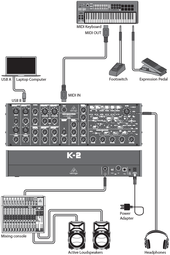
Hook-Up
Studio System
Band / Practice System

Live System
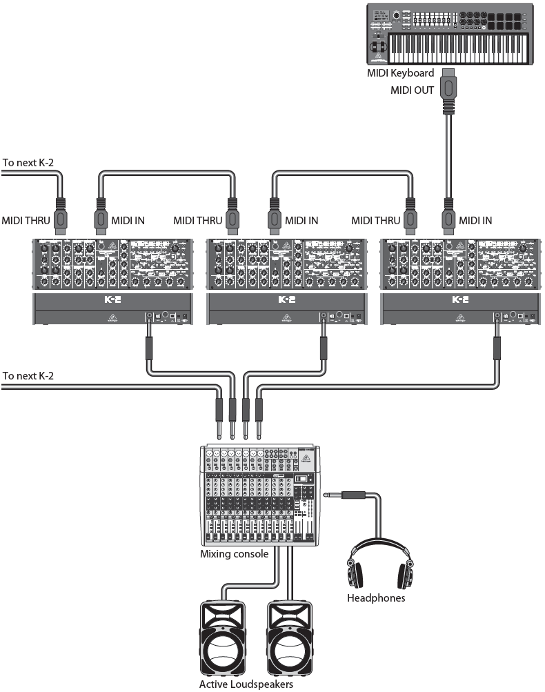
Poly Chain System
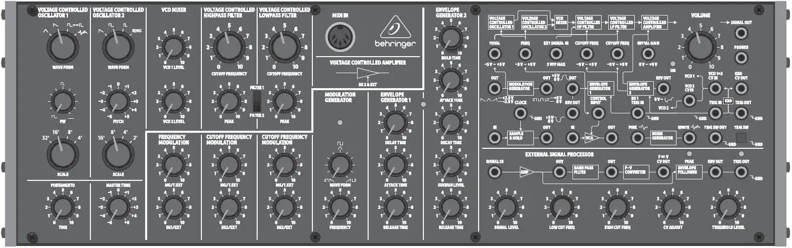
Controls
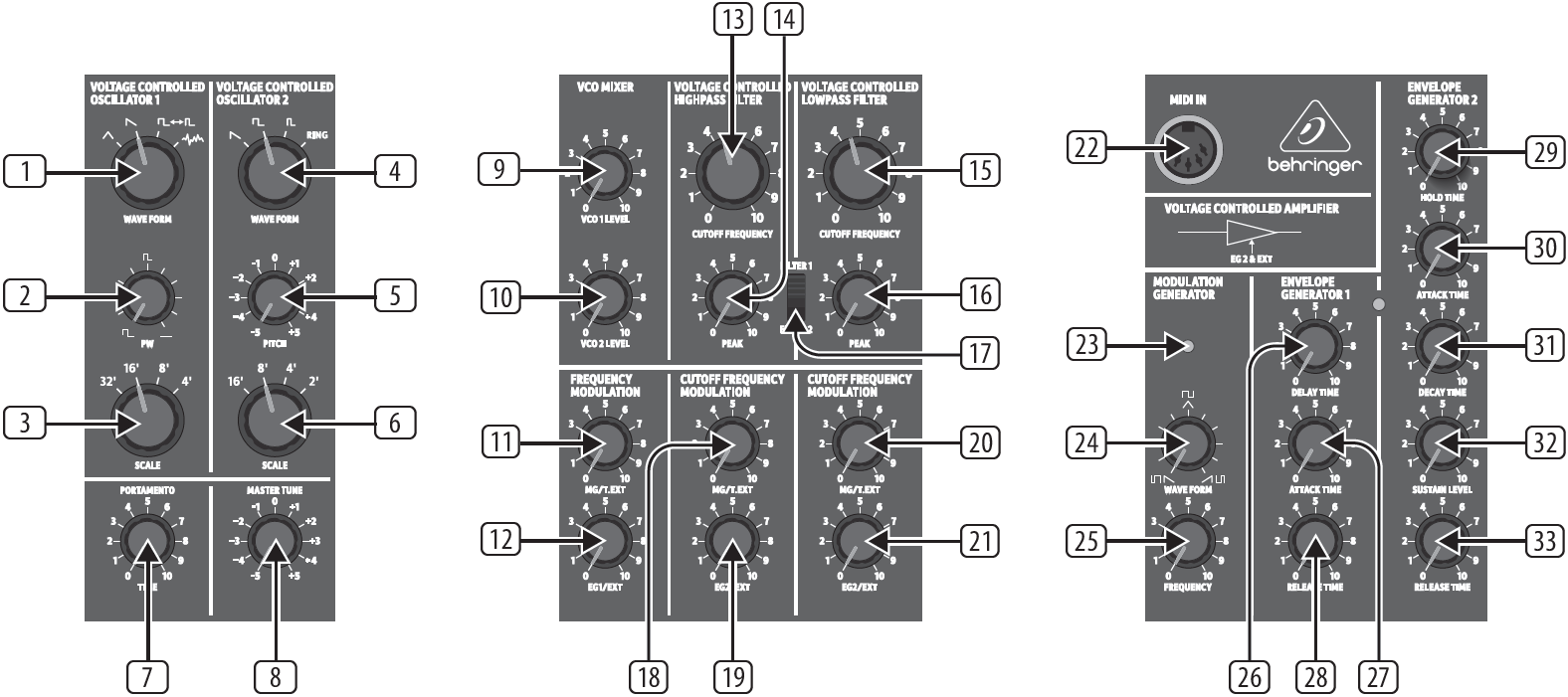
Voltage Controlled Oscillators Section
- WAVEFORM – select the VCO 1 waveform from: triangular, reverse sawtooth, pulse, or noise.
- PW – adjust the VCO 1 pulse width (when in pulse mode) from square to narrow.
- SCALE – select the VCO 1 octave from 32′, 16′, 8′, or 4′.
- WAVEFORM – select the VCO 2 waveform from: reverse sawtooth, square, narrow pulse, or RING (with VCO1).
- PITCH– adjust the VCO 2 pitch.
- SCALE– Select the VCO 2 octave from 16′, 8′, 4′, or 2′.
Controllers Section
- PORTAMENTO – adjust the amount of Portamento (Glide time), between notes on the keyboard.
- MASTER TUNE – adjust the overall tuning of the synthesizer to match other instruments.
VCO Mixer Section
- VCO1 LEVEL – adjust the VCO 1 amplitude level.
- VCO 2 LEVEL – adjust the VCO 2 amplitude level.
Frequency Modulation Section
- MG/T.EXT – adjust the amount of frequency modulation by the modulation generator (MG) or T.EXT (if a connection is made to the TOTAL input).
- EG1/EXT – adjust the amount of frequency modulation by envelope generator 1 (EG1) or EXT (if a connection is made to the FREQ input).
Voltage Controlled Filter Section
- CUTOFF FREQUENCY – adjust the cutoff frequency of the high-pass filter. Frequencies below the cutoff will be attenuated.
- PEAK – select the amount of emphasis in level at the cutoff frequency.
- CUTOFF FREQUENCY – adjust the cutoff frequency of the low-pass filter. Frequencies above the cutoff will be attenuated.
- PEAK – select the amount of emphasis in level at the cutoff frequency.
- FILTER 1/2 – select between filter type 1 or 2.
Cutoff Frequency Modulation Section
- MG/T.EXT – adjust the amount of cutoff frequency modulation of the high-pass filter by the modulation generator (MG) or T.EXT (if a connection is made to the TOTAL input).
- EG2/EXT – adjust the amount of cutoff frequency modulation of the high-pass filter by the envelope generator 2 (EG2) or EXT (if a connection is made to the high pass filter CUTOFF FREQ input).
- MG/T.EXT – adjust the amount of cutoff frequency modulation of the low-pass filter by the modulation generator (MG) or T.EXT (if a connection is made to the TOTAL input).
- EG2/EXT – adjust the amount of cutoff frequency modulation of the low-pass filter by envelope 2 (EG2) or EXT (if a connection is made to the low-pass filter CUTOFF FREQ input).
MIDI IN Section
- MIDI IN – this 5-pin DIN jack receives MIDI data from an external source. This will commonly be a MIDI keyboard, an external hardware sequencer, a computer equipped with a MIDI interface, etc.
Modulation Generator Section
- LED – indicates the current rate of the modulation generator.
- WAVEFORM – adjust the waveform of the modulation generator from reverse sawtooth, through triangle, to sawtooth. It also affects the second available waveform from wide, square, to narrow.
- FREQUENCY – adjust the frequency of the modulation generator from 0.1 to 22 Hz. The generator is also known as a low frequency oscillator (LFO).
Envelope Generator Section
Envelope 1 affects the frequency modulation.Envelope 2 affects the cutoff frequency modulation, as well as the amplitude modulation of the voltage controlled amplifier (VCA).
- DELAY TIME – controls the time between the arrival of the trigger signal and the start of the attack time.
- ATTACK TIME – controls the time it takes for envelope 1 to reach a maximum level after a note is played.
- RELEASE TIME – controls the release time of envelope 1 after the note is released.
- HOLD TIME – controls the amount of time that the trigger signal is held (extended).
- ATTACK TIME – controls the attack time of envelope 2.
- DECAY TIME – controls the decay time of envelope 2 after the attack time is over.
- SUSTAIN LEVEL – controls the level of envelope 2 that is sustained after the attack time and initial decay time have been reached.
- RELEASE TIME – controls the release time of envelope 2 after the note is released.
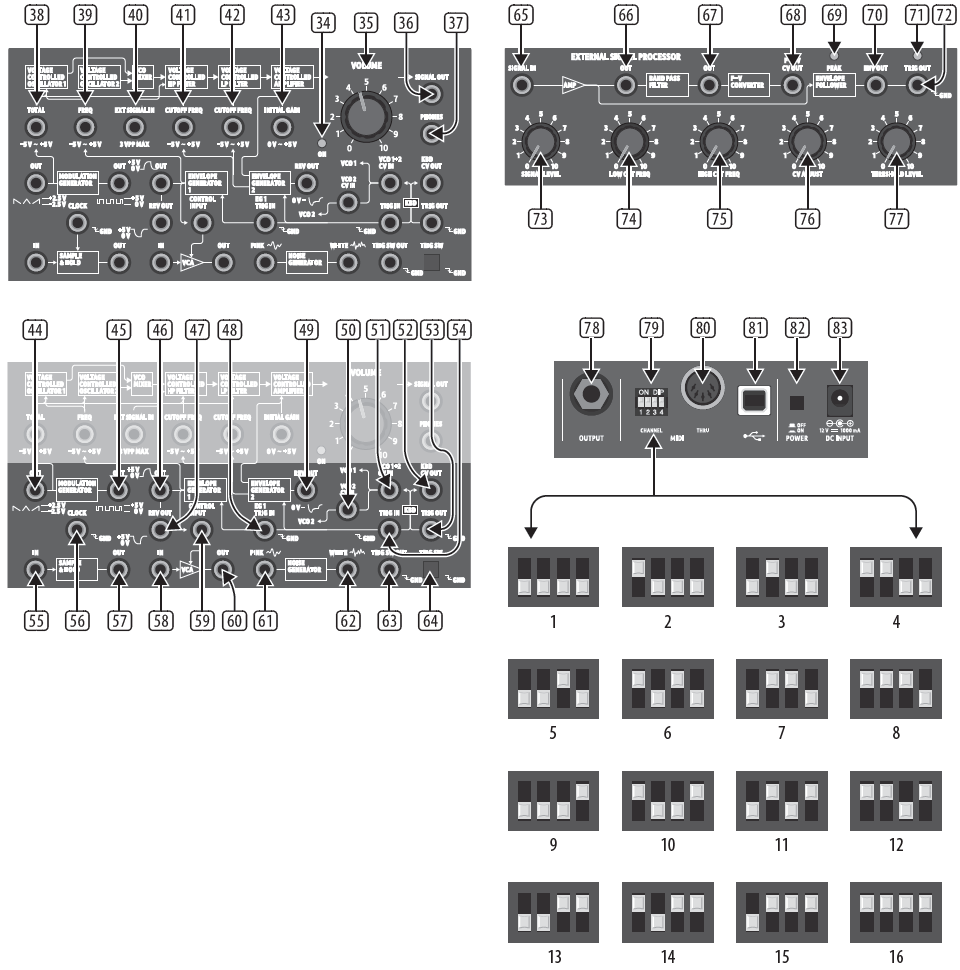
General Section
- POWER LED – this indicates when power is supplied to the unit, and the rear panel power switch is on.
- VOLUME – adjust the overall volume level of the synthesizer output.
- SIGNAL OUT – use this 3.5 mm TS connection to output the main line-level audio signals.
- PHONES – connect your headphones to this 3.5 mm TRS output. Make sure the volume is turned down before putting on headphones.
Patchbay (3.5 mm TS connections) Main Signal Path
- TOTAL – modulation input for VCO 1, VCO 2, high-pass, and low-pass VCF.
- FREQ – modulation input for VCO 1 and VCO 2.
- EXT SIGNAL IN – external audio signal input.
- CUTOFF FREQ – high-pass cutoff frequency modulation input.
- CUTOFF FREQ – low-pass cutoff frequency modulation input.
- INITIAL GAIN – VCA modulation input.
Modulation and Envelopes
- MG OUT – modulation generator output (reverse sawtooth/triangle/sawtooth).
- MG OUT – modulation generator output (wide pulse/square/narrow).
- EG 1 OUT – envelope generator 1 output.
- EG 1 REV OUT – envelope generator 1 output-reversed.
- EG1 TRIG IN – envelope 1 trigger input.
- EG 2 REV OUT – envelope generator 2 output-reversed.
- VCO 2 CV IN – VCO 2 CV input.
- VCO 1+2 CV IN – VCO 1 and VCO 2 CV input.
- KBD CV OUT – keyboard CV output.
- TRIG OUT – trigger output.
- TRIG IN – trigger input.
Sample and Hold
- S&H IN – sample and hold input.
- CLOCK – sample and hold clock input.
- S&H OUT – sample and hold output.
VCA
- VCA IN – VCA input.
- VCA CONTROL INPUT – VCA control input.
- VCA OUT – VCA control output.
Noise Generator
- PINK – output from the pink noise generator.
- WHITE – output from the white noise generator.
- TRIG SW OUT – trigger switch output.
- TRIG SW- manual trigger switch.
External Signal Processor Section
- SIGNAL IN – external signal input.
- OUT – external signal output, pre-filter.
- OUT – external signal output, post-filter.
- F – V CV OUT – CV output after frequency to voltage conversion.
- PEAK – LED indicates peak signal.
- ENV OUT – envelope output.
- LED – indicates trigger output
- TRIG OUT – trigger output.
- SIGNAL LEVEL – adjusts the external input signal level.
- LOW CUT FREQ – adjusts lower frequency of band-pass filter.
- HIGH CUT FREQ – adjusts upper frequency of band-pass filter.
- CV ADJUST – adjusts level of CV control voltage.
- THRESHOLD LEVEL – adjusts the threshold level.
Rear Panel
- OUTPUT – connect this 1/4″ TS output to the input of your external equipment.
- MIDI CHANNEL – these 4 switches allow you to set the MIDI Channel number from 1 to 16, as shown in the chart.
- MIDI THRU – this 5-pin DIN jack is used to pass through MIDI data received at the MIDI INPUT.
- USB PORT – this USB type B jack allows connection to a computer. The K-2 will show up as a class-compliant USB MIDI device, capable of supporting MIDI in and out. USB MIDI IN – accepts incoming MIDI data froman application.USB MIDI OUT – sends MIDI data to an application.
- POWER – turn the synthesizer on or off. Make sure all the connections are made before turning on the unit.
- DC INPUT – connect the supplied 12V DC power adapter here. The power adapter can be plugged into an AC outlet capable of supplying from 100V to 240V at 50 Hz/60 Hz. Use only the power adapter supplied.
Getting Started
OVERVIEW
This ‘getting started’ guide will help you set up the K-2 analog synthesizer and briefly introduce its capabilities.
CONNECTION
To connect the K-2 to your system, please consult the connection guide earlier in this document. Caution: Do not overload the 3.5 mm inputs. They can only accept the correct level of voltages as shown in the specification tables.The 3.5 mm outputs should only be connected to inputs capable of receiving the output voltages. Failure to follow these instructions may damage the K-2 or external units.
SOFTWARE SETUP
The K-2 is a USB Class Compliant MIDI device, and so no driver installation is required. The K-2 does not require any additional drivers to work with Windows and MacOS.
HARDWARE SETUP
Make all the connections in your system. Use the rear panel MIDI switches to set the K-2 to a unique MIDI channel in your system. Connect an external MIDI keyboard directly to the K-2 MIDI IN 5-pin DIN type input.Apply power to the K-2 using the supplied power adapter only. Ensure your sound system is turned down. Turn on the K-2 rear panel power switch.
WARM UP TIME
We recommend leaving 15 minutes or more time for the K-2 to warm up before recording or live performance. (Longer if it has been brought in from the cold.) This will allow the precision analog circuits time to reach their normal operating temperature and tuned performance.
VCO 1 and VCO 2 SECTION
The K-2 has two oscillators, VCO 1 and VCO 2. The VCO 1 waveform can be selected from triangle, reverse-sawtooth, pulse, and noise. When pulse is selected, the pulse width can be varied from squarewave to narrow pulse. The frequency scale can be selected from 32′, 16′, 8′, and 4′. The VCO 2 waveform can be selected from reverse-sawtooth, square, narrow pulse, and ring. When ring is selected, both oscillators are used. The VCO 2 pitch can be varied independently. The VCO 2 frequency scale can be selected from 16′, 8′, 4′ and 2′.
VCO MIXER SECTION
The VCO Mixer section allows you to adjust the volume of VCO 1 and VCO 2 to create an overall mix. Initially, you might just try just turning the VCO 1 level up, leaving VCO 2 at 0. In the Output section, adjust the main volume. Now, if you play a note on your MIDI keyboard, you should hear the sound of Oscillator 1 only. Turn up the VCO 2 level to create a mix, and adjust the VCO 2 controls as needed to create interesting effects.
FILTER SECTION
Play with the cutoff frequency, and peak controls, and listen to their effects on the sound. The high-pass and low-pass filters allow a great deal of control over the sounds achievable by K-2. The high-pass filter reduces the level of signals that are below the cutoff frequency. It effectively reduces the level of the fundamental, and lower order harmonics. The low-pass filter reduces the level of signals that are above the cutoff frequency. It reduces the levels of the higher-order harmonics. The peak control gives an emphasis in level to the signals at the crossover frequency.
FREQUENCY MODULATION SECTION
The two controls in this section allow the frequency of the oscillators to be modulated. If no other connections are made, the default modulation sources are the modulation generator (MG) and envelope generator 1 (EG 1). Turning each control will vary the depth of the modulation from each source.
CUTOFF FREQUENCY MODULATION SECTION
The controls in this section allow the high-pass and low-pass cutoff frequencies to be modulated. If no other connections are made, the default modulation sources are the modulation generator (MG) and envelope generator 2 (EG 2). Turning each control will vary the depth of the modulation from each source.
MODULATION GENERATOR SECTION
The modulation generator has two main waveform types, and each can be adjusted using the waveform control. The default type can be varied from reverse sawtooth, to triangle, to sawtooth. The other can be varied from negative narrow pulse, to square, to positive narrow pulse. The frequency of the modulation can be varied by the frequency control in this section.
ENVELOPE GENERATOR 1 SECTION
Envelope generator 1 can be used to modulate the frequency of the oscillators, as mentioned in the frequency modulation section above. The controls for delay time, attack time, and release time allow you to adjust the envelope shape.
ENVELOPE GENERATOR 2 SECTION
Envelope generator 2 can be used to modulate the cutoff frequency of the high-pass and low-pass filters, and to control the output of the VCA.The controls for hold time, attack time, decay time, sustain level, and release time allow you to adjust the envelope shape.
EXTERNAL SIGNAL PROCESSOR SECTION
This section allows you to enter the audio from an external source and to adjust its level, apply high-pass and low-pass filtering, and use it for controlling the synthesizer through patching.
PATCH BAY SECTION
This section is essentially an “interactive block diagram” of the synthesizer, and allows you to see the overall signal flow. The printed lines between blocks show the internal connections. Patching different blocks together overrides the internal connections, and allows you the versatility to create many different sounds with the synthesizer.
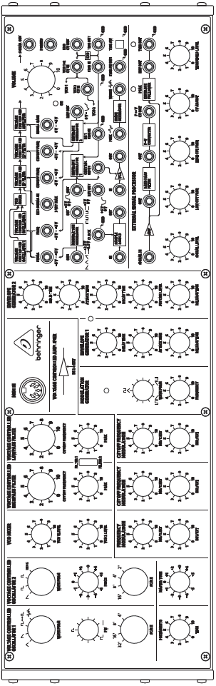
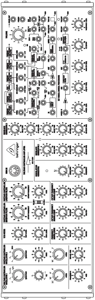
EURORACK
The K-2 synthesizer can be taken out of its factory chassis and fitted into a standard Eurorack case (not supplied).
FIRMWARE UPDATE
Please check our website behringer.com regularly for any updates to the firmware of your K-2 synthesizer. The firmware file can be downloaded and stored on your computer, and then used to update the K-2. It comes with detailed instructions on the update procedure.
HAVE FUN
The K-2 has many useful controls to create new sounds and recreate many different instruments. The patch bay allows for further experimentation and expansion to other K-2 units and modular synthesizer equipment.With all these controls, the possibilities for musical creativity are endless, rather like an artist with a new box of paints. We hope that you will enjoy your new K-2.
K-2 Poly Chain

|
System Mode LED |
|
|
ON LED |
Mode |
| Amber | Normal Mode |
| Red | Poly Chain Mode |
- Please use “SynthTool.exe” to configure the poly chain
- To enter or exit the poly chain mode, quickly press TRIG SW on the K-2 four times after powering up, while the ON LED is flashing.
- The ON LED will light red during poly chain mode.
K-2 MIDI
MIDI Message
| Channel Message |
Status |
Second |
Third |
Parameter |
Description |
|
8n |
kk |
vv |
[0, 7F] |
Note off |
|
|
9n |
kk |
vv |
[0, 7F] |
Note on |
|
|
Bn |
7B |
— |
— |
All notes off |
|
|
En |
bb |
bb |
[0, 3FFF] |
Pitch bend |
K-2 Patch Sheet
K-2 Default Patch
Specifications
|
Synthesizer Architecture |
|
| Voices | Monophonic |
| Type | Analog |
| Oscillators | 2 (16 Hz to 1.5 kHz @ 8′ and with 4 overlapping ranges) |
| LFO | 1 (0.1 to 22 Hz) |
| VCF | 1 low pass, 1 high pass (24 dB/octave slope) |
| Envelopes | VCA, VCF |
|
Connectivity |
|
| input | DC input connector |
| Power switch | Push button On/Off |
| MIDI In/Thru | MIDI In and MIDI Thru, 5-pin DIN |
| MIDI channel switch | Channel selection/ 16 channels |
| USB (MIDI) | USB 2.0, type B |
| Outputs | Output: 1/4″ TS, unbalanced, max. 0 dBu |
| Signal out: 3.5mm TS, unbalanced, max. 0 dBu | |
| Outputs impedance | 1.0 kΩ |
| Headphones | 3.5 mm TRS, max. +6 dBu |
| Headphones output impedance | 22 Ω |
| USB | |
| Type | Class compliant USB 2.0, type B |
| Supported Operating Systems | Windows 7 or higher |
| Mac OS X 10.6.8 or higher | |
|
Controllers Section |
|
| Controls | Master tune: -5 to +5 |
| Portamento: 0 to 10 | |
|
Voltage Controlled Oscillators (VCO) |
|
| Controls | Range (VCO 1): 32′, 16′, 8′, 4′ |
| Range (VCO 2): 16′, 8′, 4′, 2′ | |
| Pulse width (VCO 1): square to narrow | |
| Waveform (VCO 1): triangular, reverse sawtooth, pulse, noise | |
| Waveform (VCO 2): reverse sawtooth, square, narrow pulse, ring | |
| Pitch (VCO 2): -5 to +5 | |
|
VCO Mixer Section |
|
| Controls | VCO 1 level: 0 to 10
VCO 2 level: 0 to 10 |
|
Voltage Controlled Filter Section |
|
| Controls | High pass cutoff frequency:0 to 10 (10 Hz to 20 kHz) |
| Low pass cutoff frequency: 0 to 10 (10 Hz to 20 kHz) | |
| High pass peak (resonance): 0 to 10 | |
| Low pass peak (resonance): 0 to 10 | |
| Switches | Filter selector: filter 1/filter 2 |
Other Important Information
- Register online.Please register your new Music Tribe equipment right after you purchase it by visiting musictribe.com. Registering your purchase using our simple online form helps us to process your repair claims more quickly and efficiently. Also, read the terms and conditions of our warranty, if applicable.
- Malfunction.Should your Music Tribe Authorized Reseller not be located in your vicinity, you may contact the Music Tribe Authorized Fulfiller for your country listed under “Support” at musictribe.com. Should your country not be listed, please check if your problem can be dealt with by our “Online Support” which may also be found under “Support” at musictribe.com. Alternatively, please submit an online warranty claim at musictribe.com BEFORE returningthe product.
- Power Connections.Before plugging the unit into a power socket, please make sure you are using the correct mains voltage for your particular model. Faulty fuses must be replaced with fuses of the same type and rating without exception.
Responsible Party Name: Music Tribe Commercial NV Inc.Address: 5270 Pr ocyon Street, Las Vegas NV 89118, United StatesPhone Number: +1 702 800 8290
 report this ad
![]()
References
[xyz-ips snippet=”download-snippet”]