
![]() MODAMP MODULE 1005Legendary 2500 Series Ring Modulator and VCA Module for EurorackQuick Start Guide
MODAMP MODULE 1005Legendary 2500 Series Ring Modulator and VCA Module for EurorackQuick Start Guide
LEGAL DISCLAIMER
Music Tribe accepts no liability for any loss which may be suffered by any person who relies either wholly on or in part upon any description, photograph, or statement contained herein. Technical specifications, appearances, and other information are subject to change without notice. All trademarks are the property of their respective owners. Midas, Klark Teknik, Lab Gruppen, Lake, Tannoy, Turbosound, TC Electronic, TC Helicon, Behringer, Bugera, Oberheim, Auratone, Aston Microphones, Aston Microphones, and Coolaudio are trademarks or registered trademarks of Music Tribe Global Brands Ltd. © Music Tribe Global Brands Ltd. 2021 All rights reserved.
LIMITED WARRANTY
For the applicable warranty terms and conditions and additional information regarding Music Tribe’s Limited Warranty please see complete details online at musictribe.com/warranty.
MODAMP MODULE 1005 Controls
Controls
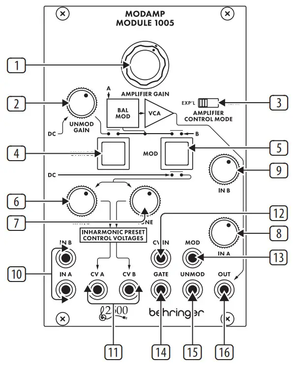
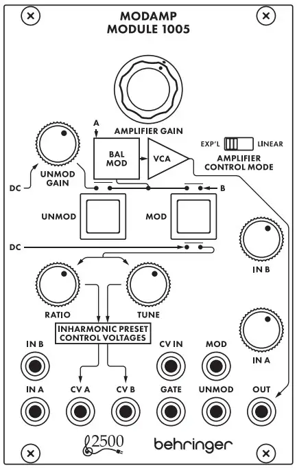
- AMPLIFIER GAIN – This knob controls the VCA’s gain and final output volume at the OUT jack.
- UNMOD GAIN – This knob controls the IN A signal gain when the module is in UNMOD mode (as indicated by the UNMOD button). UNMOD mode allows the module to be used as a VCA when modulation is not required.
- AMPLIFIER CONTROL MODE (EXP’L/LINEAR) – This sliding switch determines whether the VCA gain response is exponential (EXP’L) or linear (LINEAR).
- UNMOD – Press this button to place the module into UNMOD mode. In UNMOD mode, the IN A signal passes to the OUT jack without any modulation, and the signal level is controlled by both the UNMOD GAIN and AMPLIFIER GAIN knobs. IN B does not function in UNMOD mode.
- MOD – Press the button to activate MOD mode. In MOD mode, the circuit combines the IN A signal and the IN B signal to produce an output signal that is a modulated combination of the two input signals.
- RATIO – Use this knob in MOD mode to offset the tune control voltage that is sent out through the CV B jack. This function only operates when MOD mode is selected.
- TUNE – Use this knob in MOD mode to control the output level of the tune control voltage sent out through both the CV A and CV B jacks. This function only operateswhen MOD mode is selected.
- IN A – This knob controls the input level for the signal coming in through the IN A jack.
- IN B – This knob controls the input level for the signal coming in through the IN B jack.
- IN A / IN B – Use these input jacks to route in audio signals for the internal modulation process via cables with 3.5 mm connectors.
- CV A / CV B – Use these jacks to route TUNE (CV A and CV B) and RATIO (CV B offset) control voltages out to the two VCOs that typically supply the audio signals to the IN A and IN B inputs to be modulated.
- CV IN – Use this jack to route in control voltage signals for remote control of the AMPLIFIER GAIN setting.
- MOD – Use this jack to route in a trigger signal to remotely activate MOD mode via a cable with 3.5 mm connectors.
- GATE – Use this input jack to route in a gate signal to turn the modulation circuit on and off via a cable with 3.5 mm connectors.
- UNMOD – Use this jack to route in a trigger signal to remotely switch off MOD mode via a cable with 3.5 mm connectors.
- OUT – This jack sends out the final VCA signal via cable with 3.5 mm connectors.
Power Connection

The MODAMP MODULE 1005 module comes with the required power cable for connecting to a standard Eurorack power supply system. Follow these steps to connect power to the module. It is easier to make these connections before the module has been mounted into a rack case.
- Turn the power supply or rack case power off and disconnect the power cable.
- Insert the 16-pin connector on the power cable into the socket on the power supply or rack case. The connector has a tab that will align with the gap in the socket, so it cannot be inserted incorrectly. If the power supply does not have a keyed socket, be sure to orient pin 1 (-12 V) with the red stripe on the cable.
- Insert the 10-pin connector into the socket on the back of the module. The connector has a tab that will align with the socket for correct orientation.
- After both ends of the power cable have been securely attached, you may mount the module in a case and turn on the power supply.
Installation
The necessary screws are included with the module for mounting in a Eurorack case. Connect the power cable before mounting.Depending on the rack case, there may be a series of fixed holes spaced 2 HP apart along the length of the case, or a track that allows individual threaded plates to slide along the length of the case. The free-moving threaded plates allow precise positioning of the module, but each plate should be positioned in approximate relation to the mounting holes in your module before attaching the screws.Hold the module against the Eurorack rails so that each of the mounting holes is aligned with a threaded rail or threaded plate. Attach the screws partway to start, which will allow small adjustments to the positioning while you get them all aligned. After the final position has been established, tighten the screws down.
Specifications
Inputs
| In A / B | |
| Type | 2 x 3.5 mm TS jacks, DC-coupled |
| Impedance | 50 kO, unbalanced |
| Max input level | 10 V p.p |
| Gate | |
| Type | 1 x 3.5 mm TS jack, DC-coupled |
| Impedance | 80 kO, unbalanced |
| Max input level | +12 V |
| Minimum switching threshold | +4 V |
| Mod / un mod | |
| Type | 2 x 3.5 mm TS jacks, AC coupled |
| Impedance | 50 kO, unbalanced |
| Max input level | +12 V |
| Minimum switching threshold | +4 V |
| CV in | |
| Type | 1 x 3.5 mm TS jack, DC-coupled |
| Impedance | 100 kO, unbalanced |
| Max input level | ±10 V |
| Outputs | |
| Out | |
| Type | 1 x 3.5 mm TS jack, DC-coupled |
| Impedance | 1 kΩ, unbalanced |
| Max output level | 10 V P-P |
| CV A / B | |
| Type | 2 x 3.5 mm TS jack, DC-coupled |
| Impedance | 400 Ω, unbalanced |
| CV A Max output level | ±3 V |
| CV B Max output level | ±6 V |
| Controls | |
| Amplifier gain | -∞ to unity gain |
| Unmod gain | -∞ to unity gain |
| Amp control mode | 1 x sliding switch, Exponential/linear |
| Unmod / mod | 2 x button, LED-backlit |
| InA/B | -∞ to unity gain |
| Ratio | ±3 V @ CV B output only |
| Tune | ±3 &CVB outputs |
| Power | |
| Power supply | Eurorack |
| Current draw | 60 mA (+12 V), 45 mA (-12 V) |
| Physical | |
| Standard operating temperature range | 5°C to 40°C (41°F to 104°F) |
| Dimensions | 43 x 81 x 129 mm (1.7 x 3.2 x 5.1″) |
| Rack units | 16 HP |
| Weight | 0.16 kg (0.35 lbs) |
FEDERAL COMMUNICATIONS COMMISSION COMPLIANCE INFORMATIONBehringerMODAMP MODULE 1005Responsible Party Name: Music Tribe Commercial NV Inc.Address: 5270 Procyon Street, Las Vegas NV 89118, United StatesPhone Number: +1 702 800 8290
MODAMP MODULE 1005
This equipment has been tested and found to comply with the limits for a Class B digital device, pursuant to part 15 of the FCC Rules. These limits are designed to provide reasonable protection against harmful interference in a residential installation. This equipment generates, uses, and can radiate radio frequency energy and, if not installed and used in accordance with the instructions, may cause harmful interference to radio communications. However, there is no guarantee that interference will not occur in a particular installation. If this equipment does cause harmful interference to radio or television reception, which can be determined by turning the equipment off and on, the user is encouraged to try to correct the interference by one or more of the following measures:
- Reorient or relocate the receiving antenna.
- Increase the separation between the equipment and receiver.
- Connect the equipment into an outlet on a circuit different from that to which the receiver is connected.
- Consult the dealer or an experienced radio/TV technician for help.
This device complies with Part 15 of the FCC rules. Operation is subject to the following two conditions:
- this device may not cause harmful interference, and
- this device must accept any interference received, including interference that may cause undesired operation.
Important information:Changes or modifications to the equipment not expressly approved by Music Tribe can void the user’s authority to use the equipment.
Hereby, Music Tribe declares that this product is in compliance with Directive 2014/30/EU,Directive 2011/65/EU and Amendment 2015/863/EU, Directive 2012/19/EU, Regulation519/2012 REACH SVHC and Directive 1907/2006/EC.Full text of EU DoC is available at https://community.musictribe.com/EU Representative: Music Tribe Brands DK A/SAddress: Ib Spang Olsens Gade 17, DK – 8200 Aarhus N, Denmark
 report this ad
![]()
[xyz-ips snippet=”download-snippet”]