behringer Multi-Engine Oscillator Module for Eurorack OLED Oscilloscope

Controls
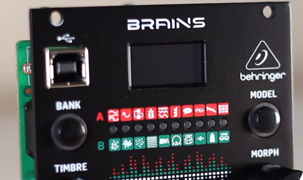
- DISPLAY – Produces a waveform of the audio content for quick visual feedback.
- USB – Connect a standard USB cable for firmware updates.
- BANK button – Toggles between Bank A and Bank B models.
- TIMBRE knob – Function varies depending on the model selected, but generally sweeps from darker to brighter content.
- HARMONICS knob – Function varies depending on the model selected, but generally adjusts frequency spread or tonal balance.
- TIMBRE CV LEVEL – Attenuates the voltage received at the Timbre CV input. If the CV input is not patched, and a signal is received at the Trig input, this knob will instead control the amount of modulation from the internal envelope generator.
- TIMBRE CV – Control the Timbre parameter via external control voltage.
- OUT 1 – Sends the main processed signal via 3.5 mm TS cable.
- MODEL jack – Allows model selection to be made remotely via external control voltage.
- MODEL button – Scrolls through the available models in the currently-active bank.
- MODEL LEDs – Indicate the current model via red LED for bank A or green LED for bank B.
- MORPH knob – Function varies depending on the model selected, but generally controls the panning or character.
- FREQ knob – Covers a range of 8 octaves, but can be narrowed down to 14 semitones.
- MORPH CV LEVEL – Attenuates the voltage received at the Morph CV input. If the CV input is not patched, and a signal is received at the Trig input, this knob will instead control the amount of modulation from the internal envelope generator.
- MORPH CV – Control the Morph parameter via external control voltage.
- OUT 2 – Sends an alternate or variant of the Out 1 signal via 3.5 mm TS cable.
- TRIG – Performs several functions:
- Triggers the internal envelope generator.
- Excites the physical and percussive models.
- Strikes the internal low-pass gate.
- Samples and holds the value of the Model CV input.
- HARMONICS CV – Control the Harmonics parameter via external control voltage.
- V/OCT – Controls the fundamental frequency relative to the root selected by the Freq knob.
- FM CV – Control the FM parameter via external control voltage.
- LEVEL – Opens the internal low-pass gate on the output signal, controlling both output level and brightness. Also triggers an accent when the physical or percussive models are active.
- FM CV LEVEL – Attenuates the voltage received at the FM CV input.
|
Name |
Timbre |
| Virtual analog | Square wave: narrow pulse, full square, hardsync formant |
| Waveshaping | Wavefolder amount |
| FM 2 operators | Modulation mix |
| Grains | Formant frequency |
| Additive | Most prominent harmonic |
| Chords | Chord inversion/transposition |
| Speech | Vocal tamber from deep to high |
| Karplus strong | Brightness and dust noise sensitivity |
| Super saw | Sets number of waveforms |
| Wavetable oscillator | Rotates through different waves |
| Rain | Rain grain density |
| Noise | Clock frequency |
| Dust | Particle density |
| Modal strings | Excitation brightness and dust density |
| FM drum | LP filter cutoff |
| Bass drum | Attack brightness and overdrive amount |
| Snare drum | Balance between different modes of the drum |
| Hi-hat | HP filter cutoff |
| Cowbell | Brightness |
| Toms | Tone |
![]()
[xyz-ips snippet=”download-snippet”]