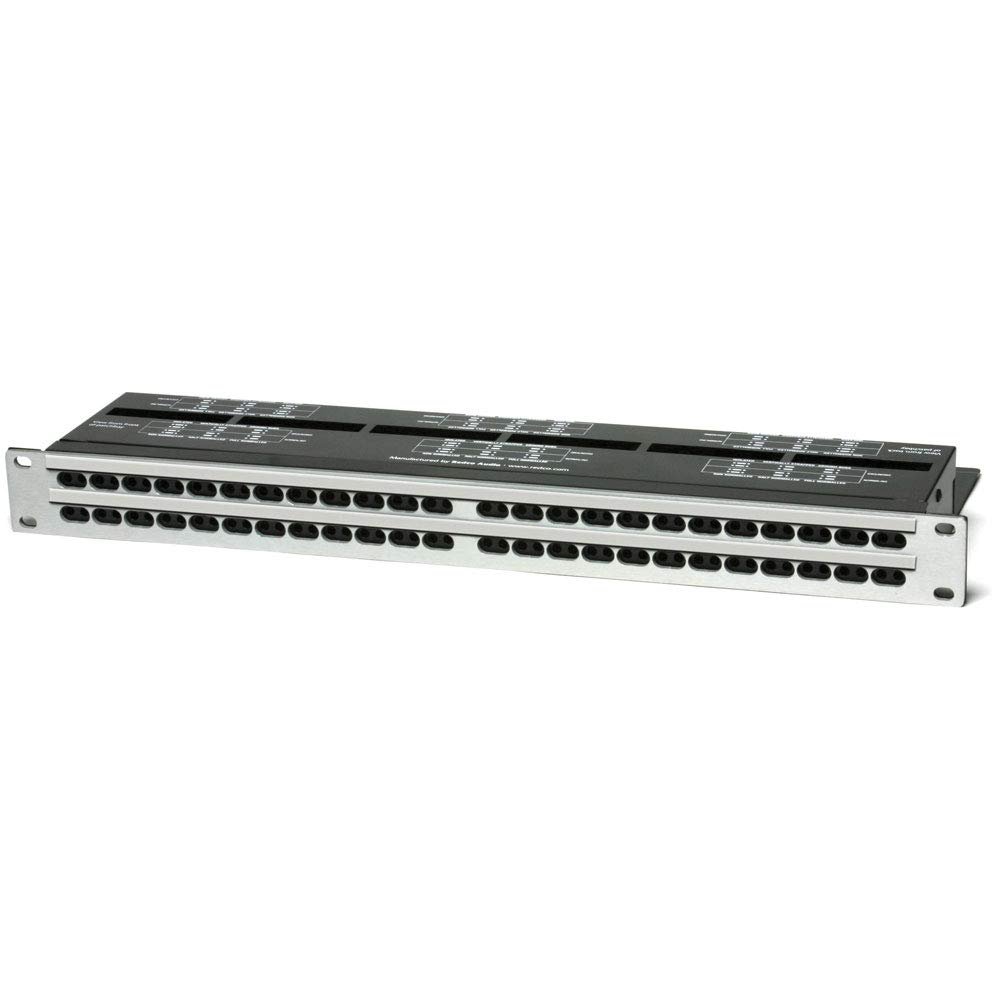
behringer Multi-Functional 48-Point 3-Mode Balanced Patchbay
Important Safety Instructions
- Terminals marked with this symbol carry electrical current of sufficient magnitude to constitute risk of electric shock.
- Use only high-quality professional speaker cables with ¼” TS or twist-locking plugs pre-installed. All other installation or modification should be performed only by qualified personnel.
- This symbol, wherever it appears, alerts you to the presence of uninsulated dangerous voltage inside the enclosure – voltage that may be sufficient to constitute a risk of shock.
- This symbol, wherever it appears, alerts you to important operating and maintenance instructions in the accompanying literature. Please read the manual.
- To reduce the risk of electric shock, do not remove the top cover (or the rear section). No user serviceable parts inside. Refer servicing to qualified personnel.
- To reduce the risk of fire or electric shock, do not expose this appliance to rain and moisture. The apparatus shall not be exposed to dripping or splashing liquids and no objects filled with liquids, such as vases, shall be placed on the apparatus.
- These service instructions are for use by qualified service personnel only. To reduce the risk of electric shock do not perform any servicing other than that contained in the operation instructions. Repairs have to be performed by qualified service personnel.
- Read these instructions.
- Keep these instructions.
- Heed all warnings.
- Follow all instructions.
- Do not use this apparatus near water.
- Clean only with dry cloth.
- Do not block any ventilation openings. Install in accordance with the manufacturer’s instructions.
- Do not install near any heat sources such as radiators, heat registers, stoves, or other apparatus (including amplifiers) that produce heat.
- Do not defeat the safety purpose of the polarized or grounding-type plug. A polarized plug has two blades with one wider than the other. A grounding-type plug has two blades and a third grounding prong. The wide blade or the third prong are provided for your safety. If the provided plug does not fit into your outlet, consult an electrician for replacement of the obsolete outlet.
- Protect the power cord from being walked on or pinched particularly at plugs, convenience receptacles, and the point where they exit from the apparatus.
- Use only attachments/accessories specified by the manufacturer.
- Use only with the cart, stand, tripod, bracket, or table specified by the manufacturer, or sold with the apparatus. When a cart is used, use caution when moving the cart/apparatus combination to avoid injury from tip-over.
- Unplug this apparatus during lightning storms or when unused for long periods of time.
- Refer all servicing to qualified service personnel. Servicing is required when the apparatus has been damaged in any way, such as power supply cord or plug is damaged, liquid has been spilled or objects have fallen into the apparatus, the apparatus has been exposed to rain or moisture, does not operate normally, or has been dropped.
- The apparatus shall be connected to a MAINS socket outlet with a protective earthing connection.
- Where the MAINS plug or an appliance coupler is used as the disconnect device, the disconnect device shall remain readily operable.
- Correct disposal of this product: This symbol indicates that this product must not be disposed of with household waste, according to the WEEE Directive (2012/19/EU) and your national law. This product should be taken to a collection center licensed for the recycling of waste electrical and electronic equipment (EEE). The mishandling of this type of waste could have a possible negative impact on the environment and human health due to potentially hazardous substances that are generally associated with EEE. At the same time, your cooperation in the correct disposal of this product will contribute to the efficient use of natural resources. For more information about where you can take your waste equipment for recycling, please contact your local city office, or your household waste collection service.
- Do not install in a confined space, such as a book case or similar unit.
- Do not place naked flame sources, such as lighted candles, on the apparatus.
- Please keep the environmental aspects of battery disposal in mind. Batteries must be disposed-of at a battery collection point.
- Use this apparatus in tropical and/or moderate climates.
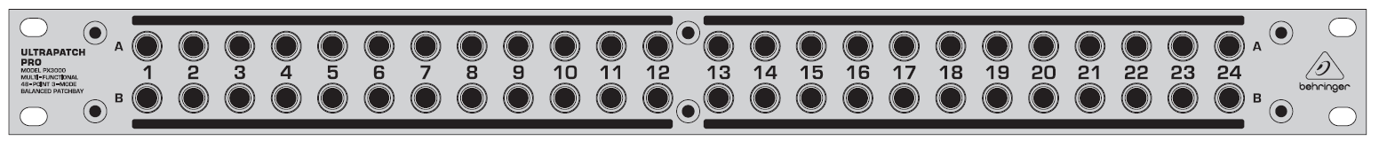
ULTRAPATCH PRO PX3000 Controls
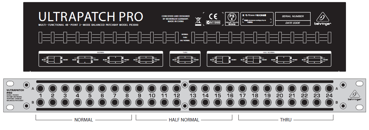
NORMAL MODE
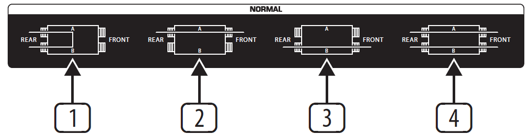
In NORMAL mode the rear A & B jacks of the channel are connected together (pos. (1)). The connection between the rear jacks is disabled when you insert a cable into jack A or B on the front panel (pos. (2) and (3)).In the example above, top-row channels 1 to 4 are from the outputs of a keyboard and a MIDI sound module. They are connected, in this example configuration, to input channels 1 to 4 on the mixer.
Channels 5 and 6 are from the subgroup outputs of a mixer and are connected, in this example configuration, to the inputs of a computer audio card. Audio sequencer software records the music signals directly onto the hard disk of the computer. Channels 7 and 8 connect the soundcard outputs to the 2-track inputs of the mixer. Since the rear-panel jacks are connected together in the Normal mode (pos. (1)), the subgroup signals can be recorded directly onto the PC and played back via the 2-track input of the mixer (playback/monitoring), without a single patch cable having to be plugged in! In this way, you can build up a basic configuration for your studio, which can be easily modified by simply patching signals via the front-panel jacks(pos. (2)) or by feeding in external signals via patch cables (pos. (3)). You could, for example, connect the keyboard signal to channels 3 and 4 by patching 1A to 3B, and 2A to 4B. So, before wiring your studio, it is advisable to identify the connections that will be used most frequently and set them up, as your basic configuration, one above the other on the patchbay. Then you will have a clear overview of all connections and still be flexible.
HALF-NORMAL MODE
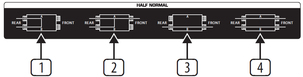
In HALF NORMAL mode, the rear A & B jacks of the channel are connected together (pos. (1)). Unlike NORMAL mode, the connection between the rear-panel jacks is not disabled when a 1/4″ plug is inserted into jack A on the front panel(pos. (2)). This allows you to take the signal from a mixers channel strip in parallel—without interrupting the signal path on the channel strip. Like NORMAL mode, the connection between the rear-panel jacks is disabled when a 1/4″ plug is inserted into jack B on the front panel (pos. (3)). When 1/4″ plugs are inserted into both jacks A & B on the front panel, the front jacks will be connected separately to the corresponding rear jacks (pos. (4)). This is called an “input break” and is used mainly to insert an effect or processor into the signal path.
In the example above, top-row channels 9 to 14 are the sends (tip contact of insert points) from mixer channels 1 to 4 plus the main left & right sends. They are connected, in this example configuration, to their respective returns (ring contacts of insert points) of the mixer.Outputs from the mixer sends can be taken from jack A without disabling the connection to the returns (pos. (2)). The mixer returns can be used as external line inputs,by patching cables to jack B (pos. (3)). External effects or processors can be inserted into the send-return loop by connecting their inputs & outputs to jacks A & B (pos. (4)).The main left & right outputs of the mixer are connected, in this example configuration, to a mini-disc recorder. However, they can also be connected in parallel to another recorder (pos. (2)). The mini-disc recorder can record other sources when they are connected to jack B of channels 15 and 16 (pos. (4))
THRU MODE
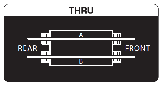
This mode is for sound modules or playback devices (e.g. CD players) that only have output signals. You can save space by routing the left and right outputs to one channel (jacks A & B) of the patchbay. A more typical setup is to connect the left and right outputs to adjacent channels (jacks A & A) and then connect another device to jacks B & B of the same channels. This configuration also allows you to position the inputs and outputs of effects devices, compressors, equalizers, etc. directly above each other.
In the example configuration above, the outputs of the playback devices (CD and mini-disc) plus the four individual outputs of a sampler are connected to channels 17 to 20, while channels 21 to 24 are used for the inputs & outputs of a compressor and an EQ, which are usually connected to the inserts of a mixer.
Specifications
Connectors: 1/4″ TRS, balancedDimensions (H x W x D): approx. 93 x 44.5 x 482.6 mm (3.7 x 1.8 x 19″)Weight: approx. 1.8 kg (4 lbs)
Important information
- Register online: Please register your new MUSIC Tribe equipment right after you purchase it by visiting behringer.com. Registering your purchase using our simple online form helps us to process your repair claims more quickly and efficiently. Also, read the terms and conditions of our warranty, if applicable.
- Malfunction: Should your MUSIC Tribe Authorized Reseller not be located in your vicinity, you may contact the MUSIC Tribe Authorized Fulfiller for your country listed under “Support” at behringer.com. Should your country not be listed, please check if your problem can be dealt with by our “Online Support” which may also be found under “Support” at behringer.com. Alternatively, please submit an online warranty claim at behringer.com BEFORE returning the product.
- Power Connections: Before plugging the unit into a power socket, please make sure you are using the correct mains voltage for your particular model. Faulty fuses must be replaced with fuses of the same type and rating without exception.
LEGAL DISCLAIMERMUSIC Tribe accepts no liability for any loss which may be suffered by any person who relies either wholly or in part upon any description, photograph, or statement contained herein. Technical specifications, appearances and other information are subject to change without notice. All trademarks are the property of their respective owners. MIDAS, KLARK TEKNIK, LAB GRUPPEN, LAKE, TANNOY, TURBOSOUND, TC ELECTRONIC, TC HELICON, BEHRINGER, BUGERA and COOLAUDIO are trademarks or registered trademarks of MUSIC Tribe Global Brands Ltd. © MUSIC Tribe Global Brands Ltd. 2018 All rights reserved.
LIMITED WARRANTY
For the applicable warranty terms and conditions and additional information regarding MUSIC Tribe’s Limited Warranty, please see complete details online at musictri.be/warranty.
![]()
References
[xyz-ips snippet=”download-snippet”]