
![]()
NX6000/NX3000/NX1000Ultra-Lightweight 6000/3000/1000-Watt Class-D Power Amplifier with SmartSense Loudspeaker Impedance Compensation
NX4-6000Ultra-Lightweight 6000-Watt 4-Channel Class-D Power Amplifier with smart sense Loudspeaker Impedance Compensation
NX6000D/NX3000D/NX1000DUltra-Lightweight 6000/3000/1000-Watt Class-D Power Amplifier with DSP Control and SmartSense Loudspeaker Impedance Compensation
Important Safety Instructions

 Terminals marked with this symbol carry an electrical current of sufficient magnitude to constitute a risk of electric shock.Use only high-quality professional speaker cables with ¼” TS or twist-locking plugs pre-installed. All other installation or modifications should be performed only by qualified personnel.
This symbol, wherever it appears, alerts you to the presence of uninsulated dangerous voltage inside the enclosure – voltage that may be sufficient to constitute a risk of shock.
 This symbol, wherever it appears, alerts you to important operating and maintenance instructions in the accompanying literature. Please read the manual.
CautionTo reduce the risk of electric shock, do not remove the top cover (or the rear section). No user-serviceable parts inside. Refer servicing to qualified personnel.
CautionTo reduce the risk of fire or electric shock, do not expose this appliance to rain and moisture. The apparatus shall not be exposed to dripping or splashing liquids and no objects filled with liquids, such as vases, shall be placed on the apparatus.
CautionThese service instructions are for use by qualified service personnel only. To reduce the risk of electric shock do not perform any servicing other than that contained in the operation instructions. Repairs have to be performed by qualified service personnel.
- Read these instructions.
- Keep these instructions.
- Heed all warnings.
- Follow all instructions.
- Do not use this apparatus near water.
- Clean only with dry cloth.
- Do not block any ventilation openings. Install in accordance with the manufacturer’s instructions.
- Do not install near any heat sources such as radiators, heat registers, stoves, or other apparatus (including amplifiers) that produce heat.
9. Do not defeat the safety purpose of the polarized or grounding-type plug. A polarized plug has two blades with one wider than the other. A grounding-type plug has two blades and a third grounding prong. The wide blade or the third prong are provided for your safety. If the provided plug does not fit into your outlet, consult an electrician for the replacement of the obsolete outlet.
10. Protect the power cord from being walked on or pinched particularly at plugs, convenience receptacles the point where they exit from the apparatus.
11. Use only attachments/accessories specified by the manufacturer.
 12. Use only with the cart, stand, tripod, bracket or table specified by the manufacturer, or sold with the apparatus. When a car is used, use caution when moving the cart/apparatus combination to avoid injury from tip-over.
 17. Correct disposal of this product: This symbol indicates that this product must not be disposed of with household waste, according to the WEEE Directive (2012/19/EU) and your national law. This product should be taken to a collection center licensed for the recycling of waste electrical and electronic equipment (EEE). The mishandling of this type of waste could have a possible negative impact on the environment and human health due to potentially hazardous substances that are generally associated with EEE. At the same time, your cooperation in the correct disposal of this product will contribute to the efficient use of natural resources. For more information about where you can take your waste equipment for recycling, please contact your local city office or your household waste collection service.18. Do not install in a confined space, such as a bookcase or similar unit.19. Do not place naked flame sources, such as lighted candles, on the apparatus.20. Please keep the environmental aspects of battery disposal in mind. Batteries must be disposed of at a battery collection point.21. This apparatus may be used in tropical and moderate climates up to 45°C.
LEGAL DISCLAIMERMusic Tribe accepts no liability for any loss which may be suffered by any person who relies either wholly on or in part upon any description, photograph, or statement contained herein. Technical specifications, appearances, and other information are subject to change without notice. All trademarks are the property of their respective owners. Midas, Klark Teknik, Lab Gruppen, Lake, Tannoy, Turbosound, TC Electronic, TC Helicon, Behringer, Bugera, Oberheim, Auratone and Coolaudio are trademarks or registered trademarks of Music Tribe Global Brands Ltd. © Music Tribe Global Brands Ltd. 2021 All rights reserved.
LIMITED WARRANTYFor the applicable warranty terms and conditions and additional information regarding Music Tribe’s Limited Warranty, please see complete details online at musictribe.com/warranty.
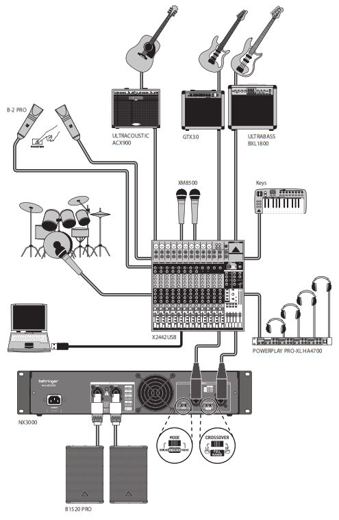
NX6000/NX3000/NX1000/NX4-6000/NX6000D/NX3000D/NX1000DNX6000/NX3000/NX1000/NX4-6000/NX6000D/NX3000D/NX1000D Hook-up
Step 1: Hook-Up
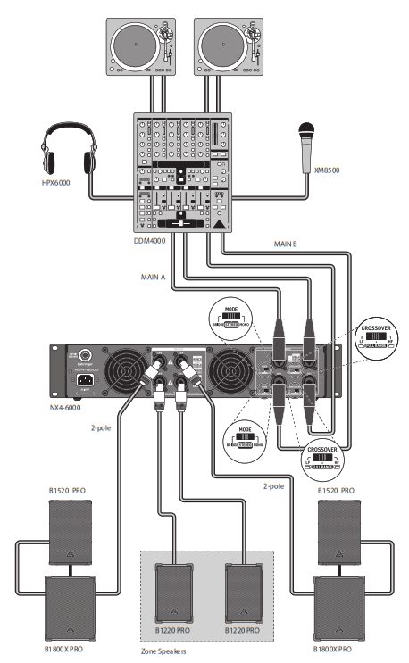 DJ Hook-upConexión para montaje de DJConfiguration DJDJ SetupConexao para DJPodłączenie DJ’aDJ aansluitingDJ-anslutningPodłączenie DJ’a
NX6000/NX3000/NX1000/NX4-6000/NX6000D/NX3000D/NX1000D
NX6000/NX3000/NX1000/NX4-6000/NX6000D/NX3000D/NX1000D Controls
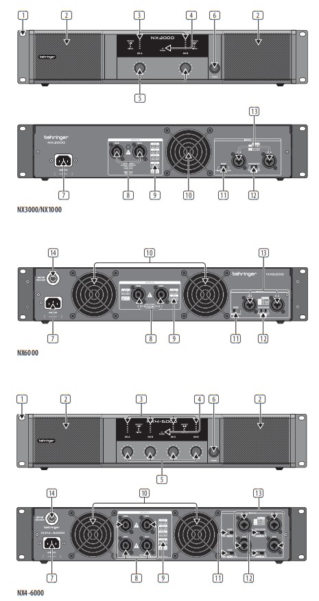
Step 2: Controls
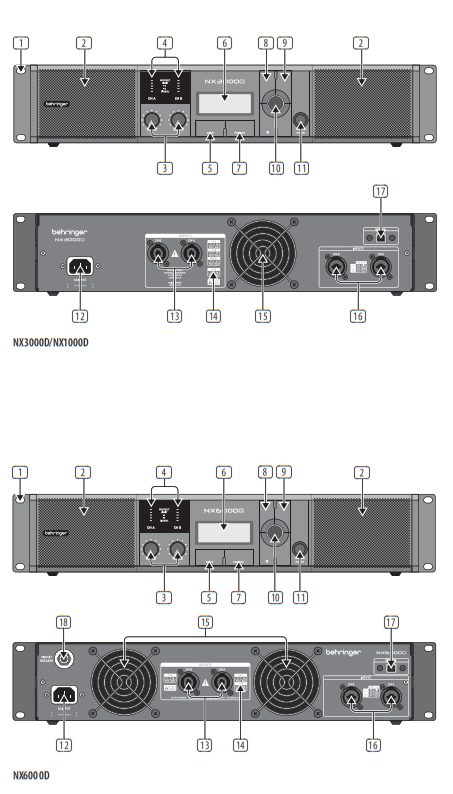
- RACK EARS secure the unit into a rack using four attaching screws and washers (fasteners not included). Requires two rack units.
- VENTILATION openings allow back-to-front air circulation to prevent overheating.
- SIGNAL, LIMIT and PROTECT LEDs display the signal level and system status for each channel. The SIGNAL LEDs light to show the input signal level. The LIMIT LED lights when the input signal exceeds an optimum level and activates the internal limiter. Reduce the input gain if the red LIMIT LED lights up continuously. The PROTECT LED shows when an operation error has occurred (over-current, over-temperature, and so on). When an operation error occurs, the PROTECT LED will light and the unit will automatically mute the channel until the error is no longer detected, after which the PROTECT LED will switch off and the amp will behave normally.
- POWER LED lights up to indicate the unit is powered on.
- INPUT CONTROLS adjust the input level. To increase signal gain, rotate the knobs clockwise; to reduce the gain, rotate the knobs counter-clockwise.
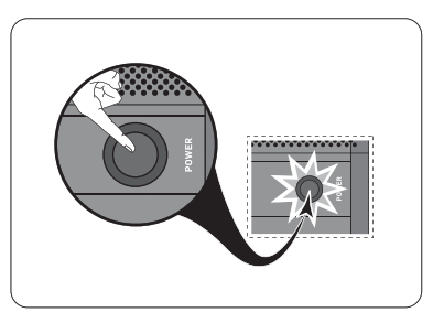
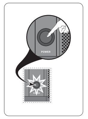
- POWER button turns the amplifier on and off.

- POWER SOURCE jack accepts the included IEC power cable.
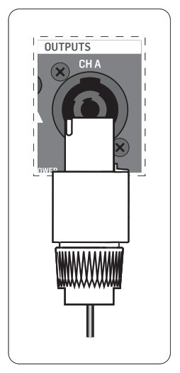
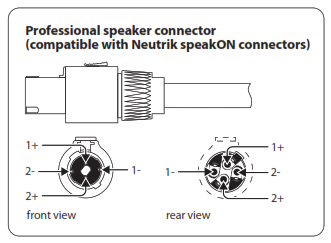
- OUTPUTS connect the amplifier to the speakers using professional speaker cables with twist-locking plugs.
- PIN OUT MATRIX lists the output pin/channel configurations available in each speaker output jack.
- VENTILATION FAN speed adjusts automatically to ensure trouble-free operation.
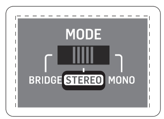
- MODE SWITCH Choose the amplifier mode by toggling the sliding MODE SWITCH between the MONO, STEREO, and BRIDGE positions (NX6000: no BRIDGE mode.)
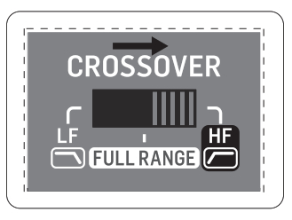
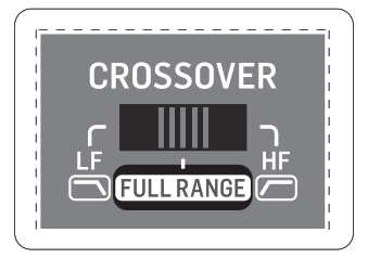
- CROSSOVER switch chooses between three modes: FULL RANGE, LF (low-frequency crossover) and HF (high-frequency crossover). In LF mode, the unit amplifies only the low frequencies of the signal. In HF mode, the unit only amplifies the high frequencies. LF and HF modes are typically used in bi-amping applications.
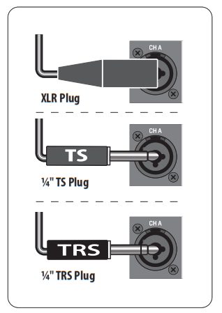
- INPUTS Route line-level input signals into these combination jacks using XLR, balanced ¼” TRS, or unbalanced ¼” TS connectors.
- BREAKER (automated fuse, NX6000 and NX4-6000 only). After eliminating the cause of faulty operation, simply depress the BREAKER and power up the unit again. The BREAKER acts in place of common discardable fuses.

BREAKER WARNING: Take the following actions BEFORE resetting the breaker:
- Unplug the AC main cable
- Press the POWER button to the extended “OFF” position
- Turn all input gain control elements down
- And then, reset the breaker, connect the unit to the mains, switch ON and slowly increase the gain to the target volume
NX6000/NX3000/NX1000/NX4-6000/NX6000D/NX3000D/NX1000D
NX6000/NX3000/NX1000/NX4-6000/NX6000D/NX3000D/NX1000D Controls
Step 2: Controls
- RACK EARS secure the unit into a rack using four attaching screws and washers (fasteners not included). Requires two rack units.
- VENTILATION openings allow back-to-front air circulation to prevent overheating.
- INPUT CONTROLS adjust the input level. To increase signal gain, rotate the knobs clockwise; to reduce the gain, rotate the knobs counter-clockwise.
- SIGNAL, LIMIT and PROTECT LED display the signal level and system status for each channel. The SIGNAL LEDs light to showthe input signal level. The LIMIT LED lights when the input signal exceeds an optimum level and activates the internal limiter.Reduce the input gain if the red LIMIT LED lights up continuously. The PROTECT LED shows when an operation error has occurred (over-current, over-temperature, and so on). When an operation error occurs, the PROTECT LED will light and the unit will automatically mute the channel until the error is no longer detected, after which the PROTECT LED will switch off and the amp will behave normally.
- SETUP button steps through parameters within DSP processing modules.
- LCD SCREEN displays the current DSP module and parameter settings.
- PROCESS button steps through the DSP processing modules.
- UP/DOWN buttons step through DSP modules.
- EXIT button takes you back to the top-level DSP screen.
- SELECT encoder knob toggles between Graphic and Edit modes (when pressed) and changes parameter values (when rotated).
- POWER button turns the amplifier on and off
- POWER SOURCE jack accepts the included IEC power cable.
- OUTPUTS connect the amplifier to the speakers using professional speaker cables with twist-locking plugs.
- PINOUT MATRIX lists the output pin/channel configurations available in each speaker output jack.
- VENTILATION FAN speed adjusts automatically to ensure trouble-free operation.
- INPUTS Route line-level input signals into these combination jacks using XLR, balanced ¼” TRS, or unbalanced ¼” TS connectors.
- USB connection enables firmware updates and control over parameters via computer. Please visit behringer.com to download DSP control software for your computer. The USB port is for amplifier configuration only.
- BREAKER (automated fuse, NX6000D). After eliminating the cause of faulty operation, simply depress the BREAKER and power up the unit again. The BREAKER acts in place of common discardable fuses.
BREAKER WARNING: Take the following actionsBEFORE resetting the breaker:
- Unplug the AC main cable
- Press the POWER button to the extended “OFF” position
- Turn all input gain control elements down
- And then, reset the breaker, connect the unit to the mains, switch ON and slowly increase the gain to the target volume
NX6000/NX3000/NX1000/NX4-6000/NX6000D/NX3000D/NX1000DNX6000D/NX3000D/NX1000D Getting started
Step 3: Getting started
- Power on the amplifier by pressing the POWER button. The startup screen will appear on the LCD display.
- Press the PROCESS button to move by step through DSP screens.
- Within each screen push the SELECT encoder knob to toggle between Graphic Mode and Edit Mode.
- In Graphic Mode, turn the SELECT encoder knob to choose the active channel and module number (e.g., DEQ filters A#1 or A#2).
- In Edit Mode, turn the SELECT encoder knob to change parameters. Press the UP/DOWN/EXIT buttons to step through values and channels.
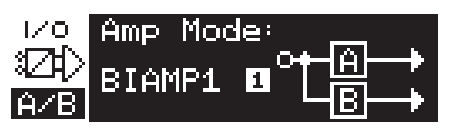
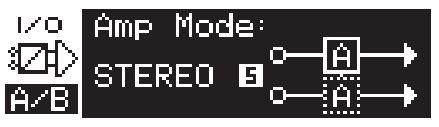
- On the I/O (Amp Mode) screen, choose your signal path: BRIDGE, DUAL (Dual Mono), STEREO, BIAMP1 or BIAMP2.
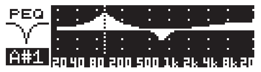
- On the PEQ screen, deploy up to 8 different parametric equalizer filters to shape your sound.
- On the XOVER screen, choose up to 2 cutoff frequency crossover points, and up to 10 different filter curves for each output.
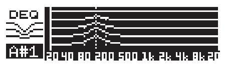
- On the DEQ screen, you may deploy Dynamic EQ modules (up to 2 per stereo channel) to monitor designated
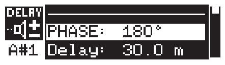
- On the DELAY screens, you may compensate for phase cancellation problems in your system by altering
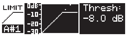
- On the Limit screen, you may implement your own threshold (Thresh[old]), release (Rtime), and hold (Hold) settings using the built-in limiters.
- Press the SETUP button to save or load presets, lock the panel and set a password, and control the LCD contrast.
- To exit to the top-level DSP screen, press the EXIT button.


NX6000/NX3000/NX1000/NX4-6000/NX6000D/NX3000D/NX1000D
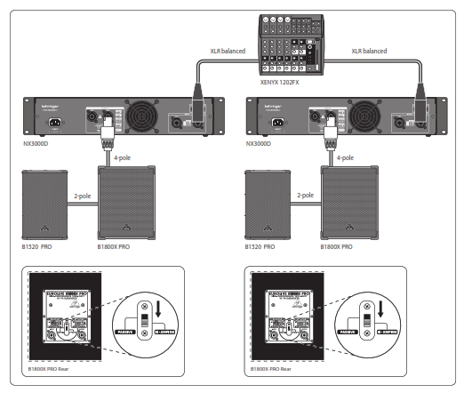
NX6000/NX3000/NX1000/NX4-6000 Bi-amping
Step 4: Bi-amping
Bi-amping splits a signal into upper and lower frequency bands and then assigns each frequency band to separate speaker cabinets. A subwoofer typically takes the low-frequency range. By splitting the signal this way, the speakers work more efficiently, and you can achieve a cleaner overall sound.
- On the amplifier intended for middle and high frequencies, slide the CROSSOVER switch to the HF position.
- On the amplifier intended for low frequencies, slide the CROSSOVER switch to the LF position.
- Set the MODE switch to STEREO.
- Run a 4-pole speaker cable with professional twist-locking connectors from each amplifier’s CH A output to a connector distribution panel. Each amplifier’s A and B channels will now be routed out together on a single cable
- Wire the distribution panel to route the HF amplifier’s CH A output (1+/1-) to pins 1+/1- of the panel’s left output, while the HF amplifier’s CH B output (2+/2-) goes to pins 1+/1- of the panel’s right output.
- Similarly, route the LF amplifier’s CH A output (1+/1-) to pins 2+/2- of the panel’s left output, while the LF amplifier’s CH B output (2+/2-) goes to pins 2+/2- of the panel’s right output.
- Now run a 4-pole cable from the distribution rack’s outputs to the subwoofers. Each 4-pole cable will have the HF amplifier’s signal on pins +/1- and the LF amplifier’s signal on the 2+/2- pins.
- Set the subwoofer to “BIAMPING” mode. On BEHRINGER subwoofers, the LF amplifier’s signal on pins 2+/2- will run the subwoofer, while the HF amplifier’s signal on 1+/1- will pass through the subwoofer to another output jack.
- Run a 2-pole speaker cable from the subwoofer’s output jack to the mid/ high-range speakers. The HF amplifier’s signal on pins 1+/1- will now drive the mid/ high-range speaker.

- Set your external crossover to split your stereo signal into low and mid/high-frequency bands at around 100 Hz.
- Run the mid/high-frequency signals from the crossovers into the CH A inputs of each amplifier.
- Run the low-frequency signals from the crossovers into the CH B inputs of each amplifier.
- On both the left and right amplifiers like the CROSSOVER switch to the FULL RANGE position.
- On both amplifiers, slide the MODE switch to the STEREO position.
- Run a 4-pole speaker cable with professional twist-locking connectors from each amplifier’s CH A output to the respective left and right subwoofers.
- Set the subwoofer into “BIAMPING” mode.
- Run a 2-pole speaker cable with professional twist-locking connectors from the subwoofer to the mid/ high-range speakers.
- Choose the BIAMP1 setting on the Amp Mode screen.
- Run a 4-pole speaker cable with professional twist-locking connectors from OUTPUTS CH A to the subwoofer. (The subwoofer receives its low-frequency signal from Channel B using poles 2+ and 2-, while the middle and upper-frequency ranges use Channel A via poles 1+ and 1-.)
- Set the subwoofer into BIAMPING mode.
- Run a 2-pole speaker cable with professional twist-locking connectors from the subwoofer to the other speaker.
- Go to the XOVER screen using the UP/ DOWN buttons to set appropriate high/ low crossover frequencies.
- In Channel A#1, choose your high-pass filter type (HPtype: BUT6, BUT12, BES12, etc.) and set the cutoff
- In Channel B#1, choose your low-pass filter type (LPtype: BUT6, BUT12, BES12, etc.) and set the cutoff frequency (LPfreq) to approximately 00 Hz. Deactivate the high-pass filter (HPtype: OFF) on this channel and set the gain level (Gain) to suit your system.

NX6000/NX3000/NX1000/NX4-6000/NX6000D/NX3000D/NX1000DNX6000D/NX3000D/NX1000D Bi-amping
Specifications
| NX6000D | NX6000 | NX4-6000 | NX4-6000 | |
| Maximum Output Power | ||||
| Stereo / 4-channel | – | 4 x 1600 W | 2 x 1500 W | |
| 4 Ω per channel, stereo | 2 x 3000 W | 4 x 860 W | 2 x 900 W | |
| 8 Ω per channel, stereo | 2 x 1600 W | 4 x 440 W | 2 x 440 W | |
| Bridge connection | ||||
| 4 Ω | – | 2 x 3000 W | 3000 W | |
| 8 Ω | – | 2 x 1600 W | 1500 W | |
| Controls | ||||
| Front | Power switch, Gain controls
(channels A and B), DSP section rotary push-encoder Buttons for Process, Setup, Up/Down, Exit |
Power switch Gain controls (channels A and B) | Power switch Gain controls (channels A,B,C and D) | Power switch, Gain controls
(channels A and B), DSP section rotary push-encoder Buttons for Process, Setup, Up/Down, Exit |
| Rear | Circuit breaker | Mode switch (stereo / mono) Crossover switch
(LF / fullrange / HF) Circuit breaker |
2 x Mode switch (bridge / stereo / mono) 2 x Crossover switch(LF / fullrange / HF) Circuit breaker | – |
| Indicators | ||||
| Power | Amber backlit LCD display | Amber LED | Amber backlit LCD display | |
| Limit (per channel) | 0 dB LED | |||
| Signal (per channel) | -40 / -6 / -3 dB LEDs | |||
| Protect (per channel) | Red LED | |||
| Input Sensitivity | ||||
| For rated power into 4 Ω | 0.775 V (0 dBu) | |||
| Digital Signal Processing (DSP) | ||||
| Display | LCD 128 x 32, amber backlit | – | LCD 128 x 32, amber backlit | |
| Digital delay function (per channel) | 0 – 300 ms | – | 0 – 300 ms | |
| Digital crossover function | 3 filter types, up to 48 dB/octave | – | 3 filter types, up to 48 dB/octave | |
| Digital EQ function (per channel) | 8-band parametric,
2-band dynamic equalizer |
– | 8-band parametric, 2-band dynamic equalizer | |
| Digital dynamics function (per channel) | Zero attack limiter (peak) | – | Zero attack limiter (peak) | |
| Presets | 20 total presets, 19 user-definable | – | 20 total presets, 19 user-definable |
| NX6000D | NX6000 | NX4-6000 |
NX3000D |
|
| Inputs | 2 x combo jacks | 4 x combo jacks | 2 x combo jacks | |
| Input impedance | 10 kΩ unbalanced, 20 kΩ balanced | |||
| Outputs | 2 x locking-style professional speaker connectors | 4 x locking-style professional speaker connectors | 2 x locking-style professional speaker connectors | |
| Output circuit type | Class D | |||
| Distortion | <0.2% | <0.1% | <0.2% | <0.3% |
| Frequency response | 20 Hz to 20 kHz, +0 / -2 dB | 20 Hz to 20 kHz, +0 / -1 dB | ||
| Damping factor | >140 @ 8 Ω | >145 @ 8 Ω | ||
| Signal-to-noise | >100 dB | |||
| USB | Rear panel USB connector type B for remote control of DSP section | — | Rear panel USB connector type B for remote control of DSP section |
| Circuit Protection | |
| Cooling | Continuously variable speed fan
Back-to-front air flow |
| Amplifier protection | Thermal and DC protection
Stable into reactive or mismatched loads |
| Load protection | On/off muting, DC-fault power supply shutdown |
| Power Supply, Voltage, Current Consumption (Breaker / Fuses) | ||||
| USA / Canada | 120 V~, 60 Hz, (T 25 A H 250 V) | 100-120 V~, 50/60 Hz,
(T 10 A H 250 V) |
||
| Japan | 100 V~, 50/60 Hz, (T 25 A H 250 V) | 100-120 V~, 50/60 Hz,
(T 10 A H 250 V) |
||
| UK / Australia / Europe | 220-240 V~, 50/60 Hz, (T 12 A H 250 V) | 220-240 V~, 50/60 Hz,
(T 6.3 A H 250 V) |
||
| Korea / China | 220-240 V~, 50/60 Hz, (T 12 A H 250 V) | 220-240 V~, 50/60 Hz,
(T 6.3 A H 250 V) |
||
| Power consumption @ 2 Ω,
1/8 rated power |
– | 620 W | 320 W | |
| Power consumption @ 4 Ω,
1/8 rated power |
620 W | 620 W | – | – |
| Mains connector | Standard IEC receptacle |
Dimensions / Weight
| Dimensions (H* x W x D) | 94 x 483 x 316 mm (3.7 x 19.0 x 12.4″) | 94 x 483 x 231 mm(3.7 x 19.0 x 9.1″) | ||
| Weight | 6.0 kg (13.2 lbs) | 5.9 kg (13.0 lbs) | 6.1 kg (13.4 lbs) | 3.6 kg (7.9 lbs) |
* including 5 mm rubber feet
|
NX6000D |
NX6000 | NX4-6000 |
NX3000D |
|
| Inputs | 2 x combo jacks | 4 x combo jacks | 2 x combo jacks | |
| Input impedance | 10 kΩ unbalanced, 20 kΩ balanced | |||
| Outputs | 2 x locking-style professional speaker connectors | 4 x locking-style professionalspeaker connectors | 2 x locking-style professionalspeaker connectors | |
| Output circuit type | Class D | |||
| Distortion | <0.2% | <0.1% | <0.2% | <0.3% |
| Frequency response | 20 Hz to 20 kHz, +0 / -2 dB | 20 Hz to 20 kHz, +0 / -1 dB | ||
| Damping factor | >140 @ 8 0 | >145 @ 8 0 | ||
| Signal-to-noise | >100 dB | |||
| USB | Rear panel USB connector type Bfor remote control of DSP section | — | Rear panel USB connector type B for remote control of DSP section |
Controls
| Front | Power switch Gain controls (channels A and B) | Power switch, Gain controls (channels A and B), DSP section rotary push-encoder Buttons for Process, Setup, Up/Down, Exit | Power switch Gain controls (channels A and B) |
| Rear | Mode switch(bridge / stereo / mono) Crossover switch (LF / fullrange / HF) | — | Mode switch(bridge / stereo / mono) Crossover switch (LF / fullrange / HF) |
Indicators
|
Power |
Amber LED | Amber backlit LCD display |
Amber LED |
| Limit (per channel) | 0 dB LED | ||
| Signal (per channel) | -40 / -6 / -3 dB LEDs | ||
| Protect (per channel) | Red LED |
Input Sensitivity
| For rated power into 4 Ω | 0.775 V (0 dBu) |
Digital Signal Processing (DSP)
| Display | — | LCD 128 x 32, amber backlit | — |
| Digital delay function (per channel) | — | 0 – 300 ms | — |
| Digital crossover function | — | 3 filter types, up to 48 dB/octave | — |
| Digital EQ function (per channel) | — | 8-band parametric, 2-band dynamic equalizer | — |
| Digital dynamics function (per channel) | — | Zero attack limiter (peak) | — |
| Presets | — | 20 total presets, 19 user-definable | — |
System
| NX3000 | NX1000D |
NX1000 |
|
| Inputs | 2 x combo jacks | ||
| Input impedance | 10 kΩ unbalanced, 20 kΩ balanced | ||
| Outputs | 2 x locking-style professional speaker connectors | ||
| Output circuit type | Class D | ||
| Distortion | <0.05% | <0.1% | <0.05% |
| Frequency response | 20 Hz to 20 kHz, +0 / -1 dB | ||
| Damping factor | >145 @ 8 Ω | >155 @ 8 Ω | |
| Signal-to-noise | >100 dB | ||
| USB | — | Rear panel USB connector type B for remote control of DSP section | — |
Circuit Protection
| Cooling | Continuously variable-speed fanBack-to-front airflow |
| Amplifier protection | Thermal and DC protection Stable into reactive or mismatched loads |
| Load protection | On/off muting, DC-fault power supply shutdown |
Power Supply, Voltage, Current Consumption (Breaker / Fuses)
| USA / Canada / Japan | 100-120 V~, 50/60 Hz, (T 10 A H 250 V) | 100-120 V~, 50/60 Hz, (T 6.3 A H 250 V) |
| UK / Australia / Europe | 220-240 V~, 50/60 Hz, (T 6.3 A H 250 V) | 220-240 V~, 50/60 Hz, (T 3.15 A H 250 V) |
| Korea / China | 220-240 V~, 50/60 Hz, (T 6.3 A H 250 V) | 220-240 V~, 50/60 Hz, (T 3.15 A H 250 V) |
| Power consumption @ 2 Ω, 1/8 rated power | 350 W | 150 W |
| Mains connector | Standard IEC receptacle |
Dimensions / Weight
| Dimensions (H* x W x D) | 94 x 483 x 231 mm (3.7 x 19.0 x 9.1″) | ||
| Weight | 3.5 kg (7.7 lbs) | 3.4 kg (7.5 lbs) | 3.3 kg (7.3 lbs) |
* including 5 mm rubber feet
Important information
- Register online. Please register your new Music Tribe equipment right after you purchase it by visiting musictribe.com. Registering your purchase using our simple online form helps us to process your repair claims more quickly and efficiently. Also, read the termsand conditions of our warranty, if applicable.
- Malfunction. Should your Music Tribe Authorized Reseller not be located in your vicinity, you may contact the Music Tribe Authorized Fulfiller for your country listed under “Support” at musictribe.com. Should your country not be listed, please check if your problem can be dealt with by our “Online Support” which may also be found under “Support” at musictribe.com. Alternatively, please submit an online warranty claim at musictribe.com BEFORE returning the product.
- Power Connections. Before plugging the unit into a power socket, please make sure you are using the correct mains voltage for your particular model. Faulty fuses must be replaced with fuses of the same type and rating without exception.
FEDERAL COMMUNICATIONS COMMISSION COMPLIANCE INFORMATION
Behinger
NX6000/NX3000/NX1000/NX4-6000/NX6000D/NX3000D/NX1000D
Responsible Party Name: Music Tribe Commercial NV Inc.Address:5270 Procyon Street, Las Vegas NV 89118, United StatesPhone Number: +1 702 800 8290
NX6000/NX3000/NX1000/NX4-6000/NX6000D/NX3000D/NX1000D
This equipment has been tested and found to comply with the limits for a Class B digital device, pursuant to part 15 of the FCC Rules. These limits are designed to provide reasonable protection against harmful interference in a residential installation. This equipment generates, uses, and can radiate radio frequency energy and, if not installed and used in accordance with the instructions, may cause harmful interference to radio communications. However, there is no guarantee that interference will not occur in a particular installation. If this equipment does cause harmful interference to radio or television reception, which can be determined by turning the equipment off and on, the user is encouraged to try to correct the interference by one or more of the following measures:
- Reorient or relocate the receiving antenna.
- Increase the separation between the equipment and receiver.
- Connect the equipment into an outlet on a circuit different from that to which the receiver is connected.
- Consult the dealer or an experienced radio/TV technician for help.This device complies with Part 15 of the FCC rules. Operation is subject to the following two conditions:(1) this device may not cause harmful interference, and(2) this device must accept any interference received, including interference that may cause undesired operation. Important information: Changes or modifications to the equipment not expressly approved by Music Tribe can void the user’s authority to use the equipment.
![]() Hereby, Music Tribe declares that this product is in compliance with Directive2014/35/EU,Directive 2014/30/EU, Directive 2011/65/EU and Amendment 2015/863/EU, Directive 2012/19/EU, Regulation 519/2012 REACH SVHC and Directive 1907/2006/EC. Full text of EU DoC is available at https://community.musictribe.com/ EU Representative: Music Tribe Brands DK A/S Address: Ib Spang Olsens Gade 17, DK – 8200 Aarhus N, Denmark
Hereby, Music Tribe declares that this product is in compliance with Directive2014/35/EU,Directive 2014/30/EU, Directive 2011/65/EU and Amendment 2015/863/EU, Directive 2012/19/EU, Regulation 519/2012 REACH SVHC and Directive 1907/2006/EC. Full text of EU DoC is available at https://community.musictribe.com/ EU Representative: Music Tribe Brands DK A/S Address: Ib Spang Olsens Gade 17, DK – 8200 Aarhus N, Denmark
We Hear You
References
[xyz-ips snippet=”download-snippet”]