Behringer Paraphonic Analog and Semi-Modular Synthesizer
Paraphonic Analog and Semi-Modular Synthesizer with Dual 3340 VCOs, Multi-Mode VCF, 2 ADSRs, BBD Delay and Overdrive Circuit in a Eurorack Format
Important Safety Instructions
- Terminals marked with this symbol carry electrical current of sufficient magnitude to constitute risk of electric shock. Use only high-quality professional speaker cables with ¼” TS or twist-locking plugs pre-installed. All other installation or modification should be performed only by qualified personnel.
- This symbol, wherever it appears, alerts you to the presence of uninsulated dangerous voltage inside the enclosure – voltage that may be sufficient to constitute a risk of shock.
- This symbol, wherever it appears, alerts you to important operating and maintenance instructions in the accompanying literature. Please read the manual.
- To reduce the risk of electric shock, do not remove the top cover (or the rear section). No user serviceable parts inside. Refer servicing to qualified personnel.
- To reduce the risk of fire or electric shock, do not expose this appliance to rain and moisture. The apparatus shall not be exposed to dripping or splashing liquids and no objects filled with liquids, such as vases, shall be placed on the apparatus.
- These service instructions are for use by qualified service personnel only. To reduce the risk of electric shock do not perform any servicing other than that contained in the operation instructions. Repairs have to be performed by qualified service personnel.
- Read these instructions.
- Keep these instructions.
- Heed all warnings.
- Follow all instructions.
- Do not use this apparatus near water.
- Clean only with dry cloth.
- Do not block any ventilation openings. Install in accordance with the manufacturer’s instructions.
- Do not install near any heat sources such as radiators, heat registers, stoves, or other apparatus (including amplifiers) that produce heat.
- Do not defeat the safety purpose of the polarized or grounding-type plug. A polarized plug has two blades with one wider than the other.A grounding-type plug has two blades and a third grounding prong. The wide blade or the third prong are provided for your safety. If the provided plug does not fit into your outlet, consult an electrician for replacement of the obsolete outlet.
- Protect the power cord from being walked on or pinched particularly at plugs, convenience receptacles, and the point where they exit from the apparatus.
- Use only attachments/accessories specified by the manufacturer.
- Use only with the cart, stand, tripod, bracket, or table specified by the manufacturer, or sold with the apparatus. When a cart is used, use caution when moving the cart/apparatus combination to avoid injury from tip-over.
- Unplug this apparatus during lightning storms or when unused for long periods of time.
- Refer all servicing to qualified service personnel. Servicing is required when the apparatus has been damaged in any way, such as power supply cord or plug is damaged, liquid has been spilled or objects have fallen into the apparatus, the apparatus has been exposed to rain or moisture, does not operate normally, or has been dropped.
- The apparatus shall be connected to a MAINS socket outlet with a protective earthing connection.
- Where the MAINS plug or an appliance coupler is used as the disconnect device, the disconnect device shall remain readily operable.
- Correct disposal of this product: This symbol indicates that this product must not be disposed of with household waste, according to the WEEE Directive (2012/19/EU) and your national law. This product should be taken to a collection center licensed for the recycling of waste electrical and electronic equipment (EEE).The mishandling of this type of waste could have a possible negative impact on the environment and human health due to potentially hazardous substances that are generally associated with EEE. At the same time, your cooperation in the correct disposal of this product will contribute to the efficient use of natural resources. For more information about where you can take your waste equipment for recycling, please contact your local city office, or your household waste collection service.
- Do not install in a confined space, such as a book case or similar unit.
- Do not place naked flame sources, such as lighted candles, on the apparatus.
- Please keep the environmental aspects of battery disposal in mind. Batteries must be disposed-of at a battery collection point.
- This apparatus may be used in tropical and moderate climates up to 45°C.
LEGAL DISCLAIMERMusic Tribe accepts no liability for any loss which may be suffered by any person who relies either wholly or in part upon any description, photograph, or statement contained herein. Technical specifications, appearances and other information are subject to change without notice. All trademarks are the property of their respective owners. Midas, Klark Teknik, Lab Gruppen, Lake, Tannoy, Turbosound, TC Electronic, TC Helicon, Behringer, Bugera, Oberheim, Auratone and Coolaudio are trademarks or registered trademarks of Music Tribe Global Brands Ltd.© Music Tribe Global Brands Ltd. 2021 All rights reserved.
LIMITED WARRANTYFor the applicable warranty terms and conditions and additional information regarding Music Tribe’s Limited Warranty, please see complete details online at musictribe.com/warranty.
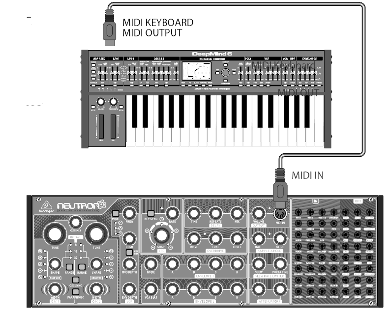
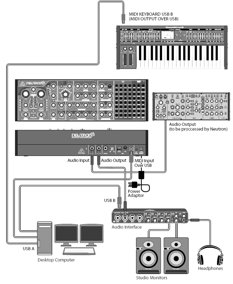
NEUTRON Hook-up
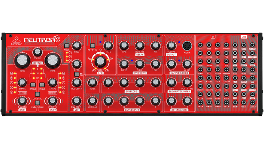
NEUTRON Controls
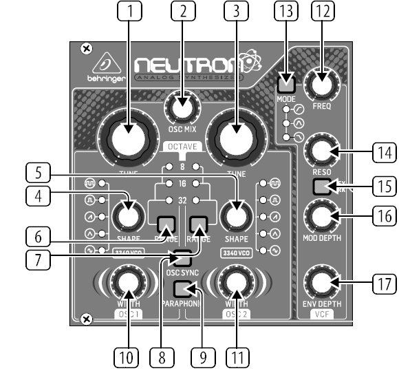
OSCILLATOR SECTION VCO (VOLTAGE CONTROLLED OSCILLATOR)
-
- OSC TUNE – Adjusts the frequency of oscillators.
- OSC MIX – Adjusts the blend between oscillator 1 and 2.
- OSC TUNE – Adjusts the frequency of oscillators.
- OSC SHAPE – Adjusts the shape of the oscillator. Can be configured to switch between fixed waveforms or to blend continuously between adjacent waveforms.
- OSC SHAPE – Adjusts the shape of the oscillator. Can be configured to switch between fixed waveforms or to blend continuously between adjacent waveforms.
- OSC RANGE – Adjusts the pipe length of oscillators between 32/16/8. +/-10 octave mode enabled when all 3 LEDs are on.
- OSC RANGE – Adjusts the pipe length of oscillators between 32/16/8. +/-10 octave mode enabled when all 3 LEDs are on.
- OSC SYNC – OSC 2 syncs to OSC 1 period.
- PARAPHONIC – Allows the two oscillators to be independently pitched when more than one MIDI note is played. If only one note is received, both oscillators will play the same pitch.
- PULSE WIDTH (PW) – Sets the pulse width of oscillator square / tone mod waveforms.
- PULSE WIDTH (PW) – Sets the pulse width of oscillator square / tone mod waveforms.VCF SECTION (VOLTAGE CONTROLLED FILTER)
- FREQ – Adjusts the cutoff frequency of the VCF.
- MODE – Selects the filter type. Choose between High Pass Filter (), Band Pass Filter () and Low Pass Filter ().
- RESO – Adjusts the resonance of the filter.
- KEY TRK – Applies keyboard tracking to the VCF.
- MOD DEPTH – Sets the depth of filter modulation from the FREQ MOD input.
- ENV DEPTH – Sets the depth of filter modulation from ENVELOPE 2.LFO SECTION (LOW FREQUENCY OSCILLATOR)
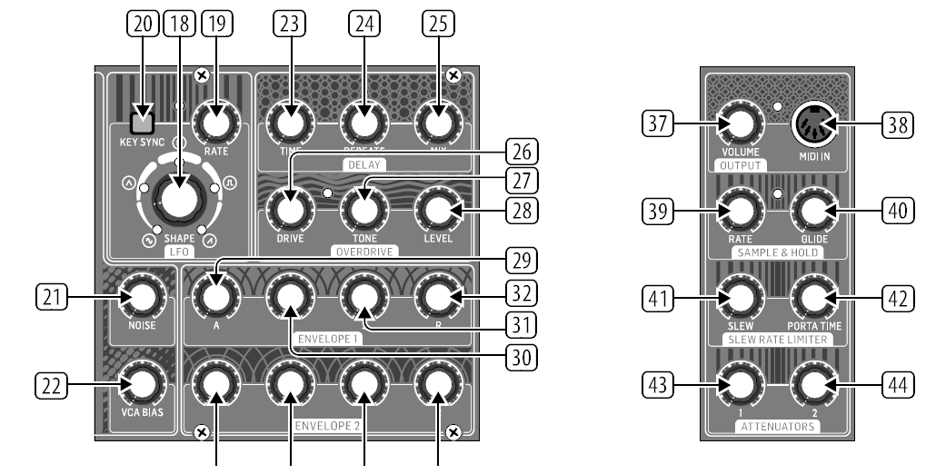
- SHAPE – Adjusts the shape of the LFO.
- RATE – Adjusts the frequency of the LFO.
- Re-trigger the LFO when a midi note is received.NOISE & VCA BIAS
- NOISE LEVEL – Adjusts the amount of white noise injected into the filter.
- VCA BIAS – Opens or closes the VCA.DELAY SECTION
- TIME – Controls the rate of the delay.
- REPEATS – Controls the number of repeats.
- MIX – Adjusts the wet/dry mix of the Delay.OVERDRIVE SECTION
-
- DRIVE – Sets the amount of overdrive.
- TONE – Changes the timbre of the overdriven sound.
- LEVEL – Controls the volume of the overdrive output. When fully off you may hear no audio at the output.ENVELOPE SECTIONENVELOPE 1: Envelope 1 is routed to the VCA CV by default.
- A [ATTACK] – Controls the attack time of the envelope.
- D [DECAY] – Controls the decay time of the envelope.
- S [SUSTAIN] – Controls the sustain level of the envelope.
- Controls the release time of the envelope.ENVELOPE 2
- A [ATTACK] – Controls the attack time of the envelope.
- D [DECAY] – Controls the decay time of the envelope.
- S [SUSTAIN] – Controls the sustain level of the envelope.
- Controls the release time of the envelope.Envelope 2 is routed to the VCF filter cutoff via ENV DEPTH control by default. See 17. ADSR knobs 33-36 function the same as 29-32.OUTPUT SECTION
- VOLUME – Controls the main output level.
- MIDI IN – Accepts incoming MIDI data from the selected midi channel.SAMPLE & HOLD CLOCKGenerates a random pattern based on the sample & hold clock.
- RATE – Controls the rate of the SAMPLE AND HOLD clock.
- GLIDE – Sets the rate of change between sample values.SLEW RATE LIMITER
- SLEW – limits the rate of change of the input signal.
- PORTA TIME – Controls the rate of change between midi notes.ATTENUATOR SECTION
- ATTENUATOR 1 – Used to reduce the amplitude of the input signal. ATT1 can be controlled by a control voltage. See 58.
- ATTENUATOR 2 – Reduces the amplitude of a signal.INPUT PATCH BAY SECTION
- OSC 1 –OSC 1 pitch CV.
- OSC 2 – OSC 2 pitch CV.
- OSC1+2 – OSC 1 and 2 pitch CV.
- INVERT IN – The input signal is inverted at INVERT OUT. See 88.
- SHAPE 1 – OSC 1 Shape CV.
- SHAPE 2 – OSC 2 Shape CV.
- PW1 – OSC 1 PW CV.
- PW2 – OSC 2 PW CV.
- VCF – VCF signal input.
- FREQ MOD – VCF cutoff frequency CV.
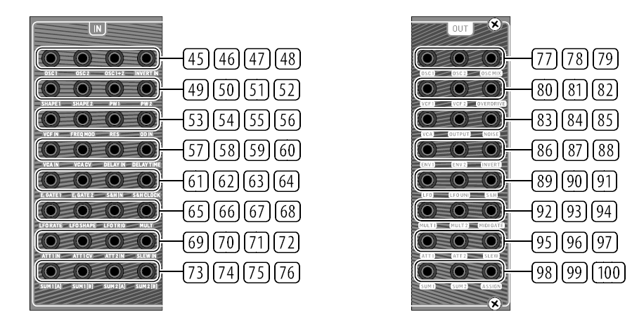
- RES – VCF resonance CV.
- OD IN – Overdrive signal input.
- VCA IN – VCA signal input.
- VCA CV – VCA CV.
- DELAY IN – Delay signal input.
- DELAY TIME – Delay time CV.
- E.GATE1 – Envelope 1 gate.
- E.GATE2 – Envelope 2 gate.
- S&H IN – Sample and Hold signal input.
- S&H CLOCK –Sample and Hold clock input.
- LFO RATE – LFO Rate CV.
- LFO SHAPE – LFO Shape CV.
- LFO TRIG – LFO Trigger input.
- MULT – MULT signal input. See 92/93.
- ATT1 IN – Attenuator 1 signal input.
- ATT1 CV – Attenuator 1 CV.
- ATT2 IN – Attenuator 2 signal input.
- SLEW IN – Slew signal input.
- SUM1(A) – SUM 1 first signal input. See 98.
- SUM1(B) – SUM1 Second signal input. See 98.
- SUM2(A) – SUM 2 first signal input. See 99.
- SUM2(B) – SUM 2 first signal input. See 99.OUTPUT PATCH BAY SECTION
- OSC 1 – Output of Oscillator 1.
- OSC 2 – Output of Oscillator 2.
- OSC Mix – Output of OSC 1/2 mix.
- VCF 1 – Main output of the filter.
- VCF 2 – Alternate output of the filter.
- OVERDRIVE – Overdrive output signal.
- VCA – Voltage Controlled Amplifier output signal.
- OUTPUT – Main output signal, post delay.
- NOISE – Output of the white noise generator.
- ENV1 – Envelope 1 output.
- ENV2 – Envelope 2 output.
- INVERT – Inverted version of signal applied to INVERT IN. See 48.
- LFO – Output of the Bipolar LFO (-5 V to +5 V).
- LFO UNI – Output of the Unipolar LFO (0V to +5 V).
- S&H – Sample and Hold output signal.
- MULT 1 – Duplicate of signal applied to MULT IN. See 68.
- MULT 2 – Duplicate of signal applied to MULT IN. See 68.
- MIDI GATE – MIDI gate output.
- ATT1 – Output of Attenuator 1.
- ATT2 – Output of Attenuator 2.
- SLEW – Output of Slew.
- SUM1 – Summation of SUM 1(A+B).
- SUM2 – Summation of SUM 2(A+B).
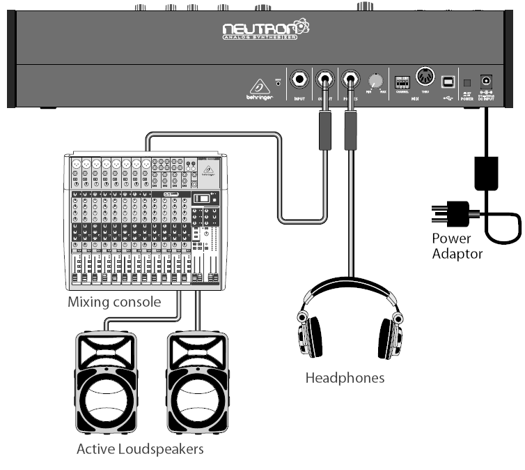
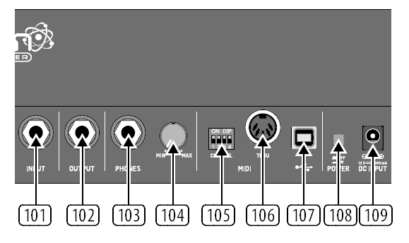
- ASSIGN – Assignable output. See User Configurable Options & Features.Step 2: ControlsREAR PANEL
- INPUT – External audio is injected into the VCF.
- OUTPUT – Connect to a mixer or audio interface using ¼” Jack cable.
- PHONES – Headphones output.
- PHONES LEVEL – Headphones level control.
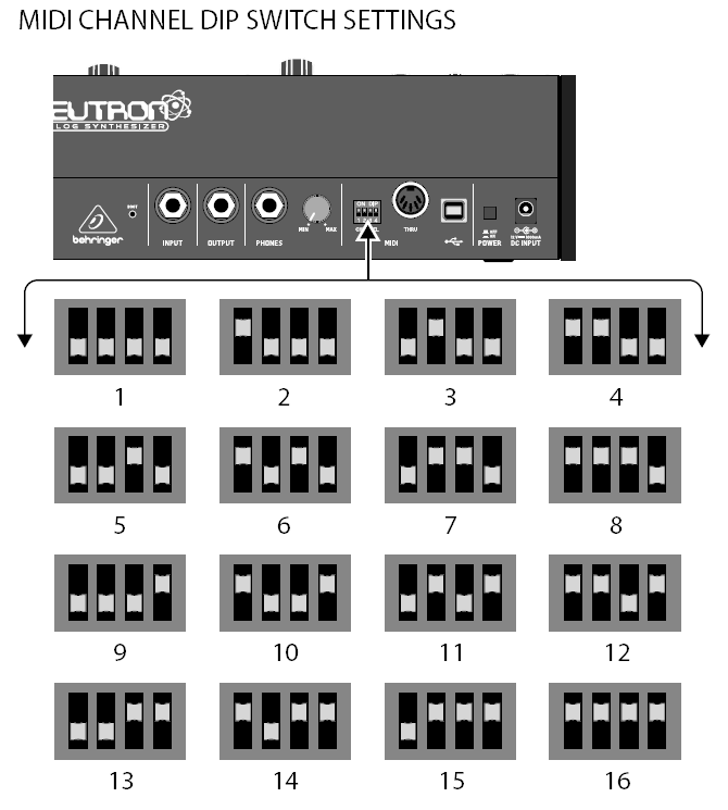
- MIDI CHANNEL SELECTION.Move the four dip switches to select the MIDI channel.
- MIDI THRU – Soft MIDI THRU.
- USB PORT – Capable of sending and receiving MIDI information over USB.
- POWER SWITCH – Turns the synthesizer on and off.
- POWER INPUT – Connect the supplied power supply only.
![]()
[xyz-ips snippet=”download-snippet”]