Behringer Preamps and British
Thank youCongratulations! In purchasing our XENYX 1202/1002/802/502 you have acquired a mixing console whose small size belies its incredible versatility and audio performance.The XENYX Series represents a milestone in the development of mixing console technology. With the new XENYX microphone preamps including phantom power as an option, balanced line inputs and a powerful effects section, the mixing consoles in the XENYX Series are optimally equipped for live and studio applications. Owing to state-of-the-art circuitry your XENYX console produces a warm analog sound that is unrivalled. With the addition of the latest digital technology these best-in-class consoles combine the advantages of both analog and digital technology.
- Terminals marked with this symbol carry electrical current of sufficient magnitude to constitute risk of electric shock.Use only high-quality professional speaker cables with ¼” TS or twist-locking plugs pre-installed. All other installation or modification should be performed only by qualified personnel.
- This symbol, wherever it appears, alerts you to the presence of uninsulated dangerous voltage inside the enclosure – voltage that may be sufficient to constitute a risk of shock.
- This symbol, wherever it appears, alerts you to important operating and maintenance instructions in the accompanying literature. Please read the manual.
- Caution: To reduce the risk of electric shock, do not remove the top cover (or the rear section). No user serviceable parts inside. Refer servicing to qualified personnel.
- Caution: These service instructions are for use by qualified service personnel only. To reduce the risk of electric shock do not perform any servicing other than that contained in the operation instructions. Repairs have to be performed by qualified service personnel.
- Read these instructions.
- Keep these instructions.
- Heed all warnings.
- Follow all instructions.
- Do not use this apparatus near water.
- Clean only with dry cloth.
- Do not block any ventilation openings. Install in accordance with the manufacturer’s instructions.
- Do not install near any heat sources such as radiators, heat registers, stoves, or other apparatus (including amplifiers) that produce heat.
- Do not defeat the safety purpose of the polarized or grounding-type plug. A polarized plug has two blades with one wider than the other. A grounding-type plug has two blades and a third grounding prong. The wide blade or the third prong are provided for your safety. If the provided plug does not fi t into your outlet, consult an electrician for replacement of the obsolete outlet.
- Protect the power cord from being walked on or pinched particularly at plugs, convenience receptacles, and the point where they exit from the apparatus.
- Use only attachments/accessories specified by the manufacturer.
- Use only with the cart, stand, tripod, bracket, or table specified by the manufacturer, or sold with the apparatus. When a cart is used, use caution when moving the cart/apparatus combination to avoid injury from tip-over.
- Unplug this apparatus during lightning storms or when unused for long periods of time.
- Refer all servicing to qualified service personnel. Servicing is required when the apparatus has been damaged in any way, such as power supply cord or plug is damaged, liquid has been spilled or objects have fallen into the apparatus, the apparatus has been exposed to rain or moisture, does not operate normally, or has been dropped.
- The apparatus shall be connected to a MAINS socket outlet with a protective earthing connection.
- Where the MAINS plug or an appliance coupler is used as the disconnect device, the disconnect device shall remain readily operable.
Introduction
The microphone channels feature high-end XENYX Mic Preamps that compare well with costly outboard preamps in terms of sound quality and dynamics and boast the following features:
- 130 dB dynamic range for an incredible amount of headroom
- A bandwidth ranging from below 10 Hz to over 200 kHz for crystal-clear reproduction of even the finest nuances
- The extremely low-noise and distortion-free circuitry guarantees absolutely natural and transparent signal reproduction
- They are perfectly matched to every conceivable microphone with up to 60 dB gain and +48 volt phantom power supply
- They enable you to use the greatly extended dynamic range of your 24- bit/192-kHz HD recorder to the full, thereby maintaining optimal audio quality
“British EQ”The equalizers used for the XENYX Series are based on the legendary circuitry of top-notch consoles made in Britain, which are renowned throughout the world for their incredibly warm and musical sound character. Even with extreme gain settings these equalizers ensure outstanding audio properties.
Caution! We should like to draw your attention to the fact that extreme volumes may damage your hearing and/or your headphones or loudspeakers. Turn the MAIN MIX control and PHONES control in the main section fully counter-clockwise before you switch on the unit. Always be careful to set appropriate volume levels.
Important notes concerning installation: The sound quality may diminish within the range of powerful broadcasting stations and high-frequency sources. Increase the distance between the transmitter and the device and use shielded cables for all connections.
General mixing console functions
A mixing console fulfils three main functions:
- Signal processing: Preamplification, level adjustment, mixing of effects, frequency equalization
- Signal distribution: Summing of signals to the aux sends for effects processing and monitor mix, distribution to one or several recording tracks, power amp(s), control room and 2-track outputs
- Mix: Setting the volume level, frequency distribution and positioning of the individual signals in the stereo field, level control of the total mix to match the recording devices/crossover/power amplifier(s). All other mixer functions can be included in this main function
The interface of BEHRINGER mixing consoles is optimized for these tasks enabling you to easily keep track of the signal path.
The user’s manual
The user’s manual is designed to give you both an overview of the controls, as well as detailed information on how to use them. In order to help you understand the links between the controls, we have arranged them in groups according to their function. The illustrations at the beginning of each chapter show the controls described in each respective chapter.
The block diagram supplied with the mixing console gives you an overview of the connections between the inputs and outputs, as well as the associated switches and controls.
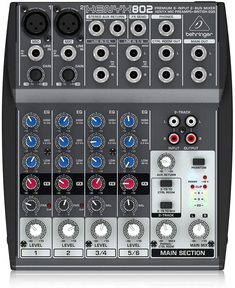
Control Elements and Connectors
This chapter describes the various control elements of your mixing console. All controls, switches and connectors will be discussed in detail.
Mono channels
Microphone and line inputs
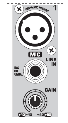
MICEach mono input channel offers a balanced microphone input via the XLR connector and also features switchable +48 V phantom power supply for condenser microphones. The XENYX preamps provide undistorted and noise-free gain as is typically known only from costly outboard preamps.
Note: Please mute your playback system before you activate the phantom power supply to prevent switch-on thumps being directed to your loudspeakers. Please also note the instructions in chapter 2.3.5“Phantom power and LED displays”.
LINE INEach mono input also features a balanced line input on a ¼” connector. Unbalanced devices (mono jacks) can also be connected to these inputs.
NOTE: Please remember that you can only use either the microphone or the line input of a channel at any one time. You can never use both simultaneously!
GAINUse the GAIN control to adjust the input gain. This control should always be turned fully counterclockwise whenever you connect or disconnect a signal source to one of the inputs.
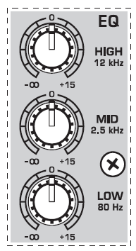
Equalizer
All mono input channels include a 3-band equalizer, except for the 502, which is equipped with a 2-band EQ. All bands provide boost or cut of up to 15 dB. In the central position, the equalizer is inactive.The circuitry of the British EQs is based on the technology used in the best-known top-of-the-line consoles and providing a warm sound without any unwanted side effects. The result are extremely musical equalizers which, unlike simple equalizers, cause no side effects such as phase shifting or bandwidth limitation, even with extreme gain settings of ±15 dB.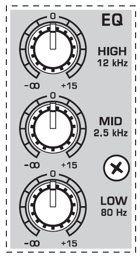
EQThe upper (HIGH) and the lower band (LOW) are shelving filters that increase or decrease all frequencies above or below their cut-off frequency. The cut-off frequencies of the upper and lower band are 12 kHz and 80 Hz respectively. The mid band (1202/1002/802) is configured as a peak filter with a center frequency of 2.5 kHz.
LOW CUTIn addition, the mono channels (1202 and 1002) are equipped with a steep LOW CUT filter (slope at 18 dB/oct., -3 dB at 75 Hz) designed to eliminate unwanted low-frequency signal components.
FX sends, panorama and level adjustment
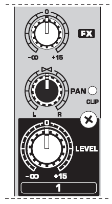
FX (1202/1002/802 only)FX sends (or AUX sends) enable you to feed signals via a variable control from one or more channels and sum these signals to a bus. The bus appears at the console’s FX send output and can be fed from there to an external effects device. The return from the effects unit is then brought back into the console on the aux return connectors (802) or normal channel inputs. Each FX send is mono and features up to +15 dB gain.As the name suggests, the FX sends of the XENYX mixing consoles are intended to drive effects devices (reverb, delay, etc) and are therefore configured post-fader. This means that the mix between dry signal and effect remains at the level determined by the channel’s aux send, irrespective of the channel fader setting. If this were not the case, the effects signal of the channel would remain audible even when the fader is lowered to zero.
PANThe PAN control determines the position of the channel signal within the stereo image. This control features a constant-power characteristic, which means the signal is always maintained at a constant level, irrespective of position in the stereo panorama.LEVELThe LEVEL control determines the level of the channel signal in the main mix.CLIPThe CLIP LED’s of the mono channels illuminate when the input signal is driven too high, which could cause distortion. If this happens, use the GAIN control to reduce the preamp level until the LED does not light anymore.
Stereo channels
Stereo line inputs
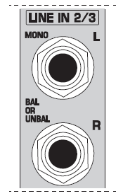
LINE INEach stereo channel has two balanced line level inputs on ¼” jacks for left and right channels. If only the jack marked “L” (left) is used, the channel operates in mono. The stereo channels are designed to handle typical line level signals.Both inputs will also accept unbalanced jacks.
Equalizer stereo channels (802)
The XENYX 802 features a stereo 3-band EQ in each stereo channel. The filter characteristics and cut-off frequencies are the same as those in themono channels.A stereo EQ is highly preferable to two mono equalizers. When working on a stereo signal, as two separate EQ’s will usually produce an unwanted discrepancy between the left and right channels.
FX sends, balance and level adjustment
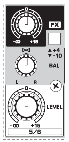
FXThe FX sends of the stereo channels function similar to those of the mono channels. However, since the FX send buses are both mono, a mono sum is first taken from the stereo input before it is sent to the FX bus. The 502 is not equipped with FXsends.BALThe BAL(ANCE) control determines the levels of left and right input signals relative to each other before both signals are then routed to the main stereo mix bus. If a channel is operated in mono via the left line input, this control has the same function as the PAN control used in the mono channels.LEVELThe LEVEL control determines the volume of the channel being sent to the main mix.+4/-10The stereo inputs of the XENYX 1202 and 1002 have an input sensitivity switch which selects between +4 dBu and -10 dBV. At -10 dBV (home-recording level), the input is more sensitive (requires less level to drive it) than at +4 dBu (studio level).
Connector panel and main section
Send/return effects path
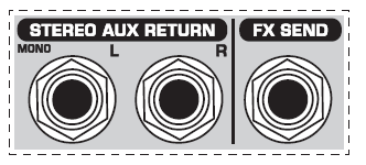
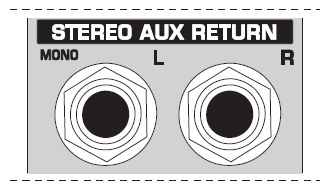
AUX RETURN802 only: the STEREO AUX RETURN connectors are used to bring the output of the external effects device (whose input is derived from the aux sends) back into the console. You can instead use these connectors as additional inputs, but any effects device will then have to be brought back into the console via a normal stereo channel. This does, however, give you the ability to use the channel EQ on the effects return signal if you wish.
When using a stereo channel as effects return path, the FX control of the relevant channel should generally be turned fully down to avoid undesirable feedback.
If only the left connector is used, the AUX RETURN automatically operates in mono. Use the AUX RETURN control to determine how much of the effects signal is sent to the main mix.
FX SENDThe FX SEND output (does not apply for 502) should be connected to the input of an external effects unit. The post-fader FX signal you created using theinput channel FX controls is sent to the effects unit via the FX SEND ouput.Use the FX SEND control of the main section to adjust the overall send level (1002 and 1202 only).
Monitor and main mix
PHONES/CONTROL ROOM
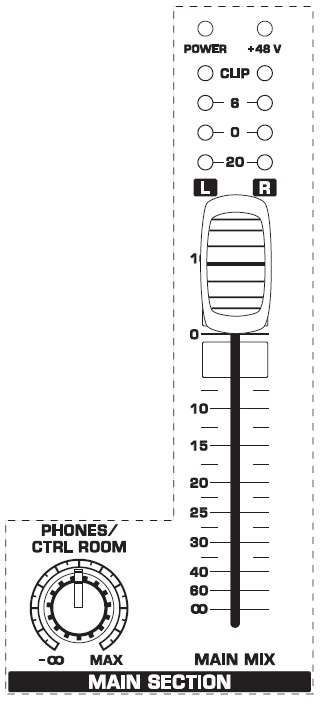
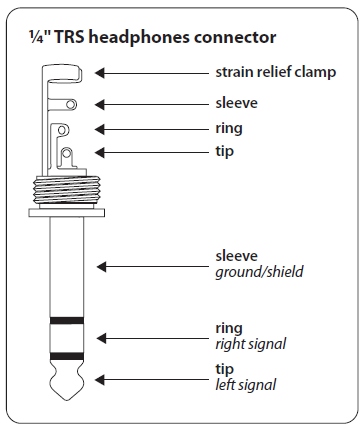
The stereo PHONES jack (at the top of the connector panel) is where you connect headphones. The unbalanced CTRL ROOM OUT jacks carry the summed effects and main mix signals, as well as soloed channel signals. The PHONES/CONTROL ROOM control adjusts the level of both headphones and main monitor outputs. The 502 is not equipped with control room outputs.

MAIN MIXThe MAIN OUT connectors are unbalanced mono jacks. The main mix signal appears here at a level of 0 dBu. The MAIN MIX fader adjusts the volume of these outputs. The XENYX 802 and 502 mixing consoles feature a rotary control for this purpose.
2-Track connectors
The 2-TRACK INPUTs are used to bring an external signal source (e.g. CD player, tape deck, etc.) into the console. They can also be used as a standard stereo line input, so the output of a second XENYX or BEHRINGER ULTRALINK PRO MX882 can be connected.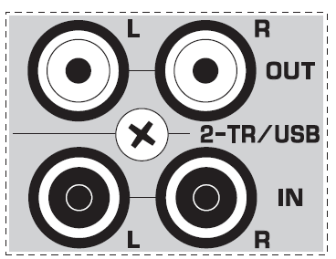
Alternatively the line or tape output of a hi-fi amplifier with source selection switch could also be hooked up here, allowing you to easily listen to additional sources.
2-TRACK OUTPUTThese connectors are wired in parallel with the MAIN OUT and carry the main mix signal (unbalanced). Connect the 2-TRACK OUTPUT to the inputs of your recording device. The output level is adjusted via the high-precision MAIN MIX fader or rotary control (802).
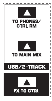
2-TR TO MIXWhen the 2-TR TO MIX switch is depressed, the 2-track input is assigned to the main mix providing an additional input for tape machines, MIDI instruments or other signal sources that do not require any processing.
2-TR TO CTRL ROOM (502: 2-TR TO PHONES)Press the 2-TR TO CTRL ROOM/PHONES switch if you want to monitor the 2-track input via the CTRL ROOM OUT. This provides an easy way to monitor signals coming back from tape to ensure that they are recording correctly.
If you are recording a signal via the 2-TRACK OUTPUT and wish to listen to this simultaneously via the 2-TRACK INPUT, do not use the 2-TR TO MIX switch. Doing this would create a feedback loop, since the signal would be routed, via the main mix, back to tape via the 2-TRACK OUTPUT. To monitor the 2-TRACK INPUT, use the 2-TR TO CTRL ROOM switch to assign the tape signal to the monitor(s) or headphones. This will avoid the tape signal being routed to the 2-TRACK OUTPUT.
FX TO CTRLIf you want to monitor only the FX send signal in your headphones or monitor speaker(s), press the FX TO CTRL switch. This mutes the main mix signal while routing the FX SEND output to the monitor(s). The XENYX 802 and 502 do not feature this switch.
Phantom power and LED displays
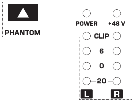
+48 VThe red +48 V LED lights up when phantom power is on. The PHANTOM switch activates the phantom power supply on the XLR connectors of all mono channels.
Please do not connect microphones to the mixer (or the stagebox/wallbox) as long as the phantom power supply is switched on. Connect the micro-phones before you switch on the power supply. In addition, the monitor/PA loudspeakers should be muted before you activate the phantom power supply. After switching on, wait approx. one minute in order to allow system stabilization.
POWERThe blue POWER LED indicates that the console is powered on.
Level indicatorThe high-precision 4-segment display accurately displays the relevantsignal level.LEVEL SETTING: To correctly set the gains of the channels, first set the LEVEL controls of the input channels to their center positions (0 dB). Then use the GAIN controls to increase the input amplification until signal peaks show 0 dB on the level meter.
When recording to digital recorders, the recorder’s peak meter should not go into overload. While analog recorders can be overloaded to some extent, creating only a certain amount of distortion (which is common and often desirable),digital recorders distort quickly when overloaded. In addition, digital distortion is not only undesirable, but also renders your recording completely useless.
The peak meters of your XENYX display the level virtually independent of frequency. A recording level of 0 dB is recommended for all signal types.
Installation
Mains connection
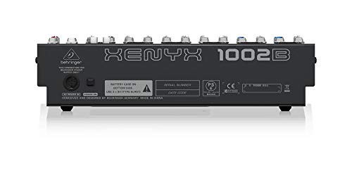
AC POWER IN
Connect the power supply to the 3-pin mains connector on the rear of the console. Use the AC adapter supplied to connect the console to the mains. The adapter complies with all applicable safety standards.
- Please use only the power supply unit provided with the console.
- Never connect the XENYX to the power supply unit while the latter is connected to the mains! First connect the console to the power supply unit, then connect the power supply unit to the mains.
- Please note that both the power supply unit and the mixing console heat up considerably during operation. This is completely normal.
Audio connections
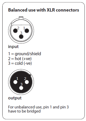
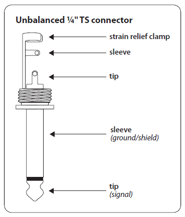
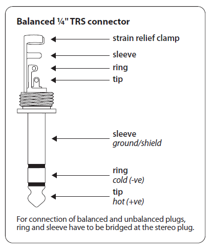
You will need a large number of cables for different applications.The illustrations below show how the connectors should be wired. Be sure to use only high-grade cables.Please use commercial RCA cables to connect the 2-track inputs and outputs.You can, of course, also connect unbalanced devices to the balanced inputs/outputs. To do this, use either mono plugs or stereo plugs with the ring and sleeve bridged (pins 1 and 3 in the case of XLR connectors).
Caution! Never use unbalanced XLR connectors (PIN 1 and 3 connected) on the MIC input connectors when using the phantom power supply.
Specifications
Microphone Inputs (XENYX Mic preamp)
Type XLR connector, electronically balanced, discrete input circuit
Frequency Response
<10 Hz – 150 kHz -1 dB<10 Hz – 200 kHz -3 dBGain range +10 dB to +60 dBMax. input level +12 dBu @ +10 dB GAINImpedance approx. 2.6 kΩ balancedSignal-to-noise ratio 110 dB / 112 dB A-weighted
Line Input
Type ¼” TRS jack, electronically balancedImpedance approx. 20 kΩ balanced, approx. 10 kΩ unbalancedGain range -10 dB to +40 dBMax. input level +22 dBu @ 0 dB GAIN
Fade-Out Attenuation2 (Crosstalk Attenuation)
Main fader closed 90 dBChannel muted 89.5 dBChannel fader muted 89 dB
Frequency Response (Mic In – Main Out)
<10 Hz – 90 kHz +0 dB / -1 dB<10 Hz – 160 kHz +0 dB / -3 dB
Stereo Inputs
Type ¼” TRS jack, electronically balancedImpedance approx. 20 kΩMax. input level +22 dBu
EQ Mono Channels
LOW 80 Hz / ±15 dBMID 2.5 kHz / ±15 dBHIGH 12 kHz / ±15 dB
EQ Stereo Channels
LOW 80 Hz / ±15 dBMID 2.5 kHz / ±15 dBHIGH 12 kHz / ±15 dB
Aux Sends
Type ¼” TS jack, unbalancedImpedance approx. 120 ΩMax. output level +22 dBu
- Equivalent Input Noise
- Measuring conditions: 1 kHz rel. to 0 dBu; 20 Hz – 20 kHz; line input; main output; unity gain.
- 20 Hz – 20 kHz; measured at main output. Channels 1 – 4 unity gain; EQ flat; all channels on main mix; channels 1/3 as far left as possible; channels 2/4 as far right as possible; reference = +6 dBu.
BEHRINGER is constantly striving to maintain the highest professional standards. As a result of these efforts, modifications may be made from time to time to existing products without prior notice. Specifications and appearance may differ from those listed or illustrated.
LEGAL DISCLAIMERTECHNICAL SPECIFICATIONS AND APPEARANCES ARE SUBJECT TO CHANGE WITHOUT NOTICE AND ACCURACY IS NOT GUARANTEED. BEHRINGER, KLARK TEKNIK, MIDAS, BUGERA, AND TURBOSOUND ARE PART OF THE MUSIC GROUP (MUSIC-GROUP.COM). ALL TRADEMARKS ARE THE PROPERTY OF THEIR RESPECTIVE OWNERS. MUSIC GROUP ACCEPTS NO LIABILITY FOR ANY LOSS WHICH MAY BE SUFFERED BY ANY PERSON WHO RELIES EITHER WHOLLY OR IN PART UPON ANY DESCRIPTION, PHOTOGRAPH OR STATEMENT CONTAINED HEREIN. COLORS AND SPECIFICATIONS MAY VARY FROM ACTUAL PRODUCT. MUSIC GROUP PRODUCTS ARE SOLD THROUGH AUTHORIZED FULLFILLERS AND RESELLERS ONLY. FULLFILLERS AND RESELLERS ARE NOT AGENTS OF MUSIC GROUP AND HAVE ABSOLUTELY NO AUTHORITY
TO BIND MUSIC GROUP BY ANY EXPRESS OR IMPLIED UNDERTAKING OR REPRESENTATION. THIS MANUAL IS COPYRIGHTED. NO PART OF THIS MANUAL MAY BE REPRODUCED OR TRANSMITTED IN ANY FORM OR BY ANY MEANS, ELECTRONIC OR MECHANICAL, INCLUDING PHOTOCOPYING AND RECORDING OF ANY KIND, FOR ANY PURPOSE, WITHOUT THE EXPRESS WRITTEN PERMISSION OF MUSIC GROUP IP LTD.ALL RIGHTS RESERVED.© 2013 MUSIC Group IP Ltd.Trident Chambers, Wickhams Cay, P.O. Box 146,Road Town, Tortola, British Virgin Islands
LIMITED WARRANTY
For the applicable warranty terms and conditions and additional information regarding MUSIC Group’s Limited Warranty, please see complete details online at www.music-group.com/warranty
References
[xyz-ips snippet=”download-snippet”]