![]() Quick Start Guide
Quick Start Guide
![]()
EURORACK PRORX1202FXPremium 12-Input Mic/Line Rack Mixer with XENYX Mic Preamplifiers, British EQ’s and Multi-FX Processor
Important SafetyInstructions

 Terminals marked with this symbol carry an electrical current of sufficient magnitude to constitute a risk of electric shock.Use only high-quality professional speaker cables with ¼” TS or twist-locking plugs pre-installed. All other installation or modifications should be performed only by qualified personnel. This symbol, wherever it appears, alerts you to the presence of uninsulated dangerous voltage inside the enclosure – voltage that may be sufficient to constitute a risk of shock.
 This symbol, wherever it appears, alerts you to important operating and maintenance instructions in the accompanying literature. Please read the manual. CautionTo reduce the risk of electric shock, do not remove the top cover (or the rear section).No user-serviceable parts inside. Refer servicing to qualified personnel. CautionTo reduce the risk of fire or electric shock, do not expose this appliance to rain and moisture. The apparatus shall not be exposed to dripping or splashing liquids and no objects filled with liquids, such as vases, shall be placed on the apparatus. CautionThese service instructions are for use by qualified service personnel only.To reduce the risk of electric shock do not perform any servicing other than that contained in the operation instructions. Repairs have to be performed by qualified service personnel.
- Read these instructions.
- Keep these instructions.
- Heed all warnings.
- Follow all instructions.
- Do not use this apparatus near water.
- Clean only with a dry cloth.
- Do not block any ventilation openings. Install in accordance with the manufacturer’s instructions.
- Do not install near any heat sources such as radiators, heat registers, stoves, or other apparatus (including amplifiers) that produce heat.
- Do not defeat the safety purpose of the polarized or grounding-type plug. A polarized plug has two blades with one wider than the other. A grounding-type plug has two blades and a third grounding prong. The wide blade or the third prong are provided for your safety. If the provided plug does not fit into your outlet, consult an electrician for the replacement of the obsolete outlet.
- Protect the power cord from being walked on or pinched particularly at plugs, convenience receptacles, and the point where they exit from the apparatus.
- Use only attachments/accessories specified by the manufacturer.
 Use only with the cart, stand, tripod, bracket, or table specified by the manufacturer, or sold with the apparatus. When a cart is used, use caution when moving the cart/apparatus combination to avoid injury from tip-over.
- Unplug this apparatus during lightning storms or when unused for long periods of time.
- Refer all servicing to qualified service personnel. Servicing is required when the apparatus has been damaged in any way, such as power supply cord or plug is damaged, liquid has been spilled or objects have fallen into the apparatus, the apparatus has been exposed to rain or moisture, does not operate normally, or has been dropped.
- The apparatus shall be connected to a MAINS socket outlet with a protective earthing connection.
- Where the MAINS plug or an appliance coupler is used as the disconnect device, the disconnect device shall remain readily operable.
- Correct disposal of this product: This symbol indicates that this product must not be disposed of with household waste, according to the WEEE Directive (2012/19/EU) and your national law. This product should be taken to a collection center licensed for the recycling of waste electrical and electronic equipment (EEE). The mishandling of this type of waste could have a possible negative impact on the environment and human health due to potentially hazardous substances that are generally associated with EEE. At the same time, your cooperation in the correct disposal of this product will contribute to the efficient use of natural resources.For more information about where you can take your waste equipment for recycling, please contact your local city office or your household waste collection service.
- Do not install in a confined space, such as a bookcase or similar unit.
- Do not place naked flame sources, such as lighted candles, on the apparatus.
- Please keep the environmental aspects of battery disposal in mind. Batteries must be disposed of at a battery collection point.
- Use this apparatus in tropical and/or moderate climates.
 Use only with the cart, stand, tripod, bracket, or table specified by the manufacturer, or sold with the apparatus. When a cart is used, use caution when moving the cart/apparatus combination to avoid injury from tip-over.
 Correct disposal of this product: This symbol indicates that this product must not be disposed of with household waste, according to the WEEE Directive (2012/19/EU) and your national law. This product should be taken to a collection center licensed for the recycling of waste electrical and electronic equipment (EEE). The mishandling of this type of waste could have a possible negative impact on the environment and human health due to potentially hazardous substances that are generally associated with EEE. At the same time, your cooperation in the correct disposal of this product will contribute to the efficient use of natural resources.For more information about where you can take your waste equipment for recycling, please contact your local city office or your household waste collection service.
LEGAL DISCLAIMER
Music Tribe accepts no liability for any loss which may be suffered by any person who relies either wholly on or in part upon any description, photograph, or statement contained herein. Technical specifications, appearances, and other information are subject to change without notice. All trademarks are the property of their respective owners. Midas, Klark Teknik, Lab Gruppen, Lake, Tannoy, Turbosound, TC Electronic, TC Helicon, Behringer, Bugera, Auratone, and Coolaudio are trademarks or registered trademarks of Music Tribe Global Brands Ltd. © Music Tribe Global Brands Ltd. 2020 All rights reserved.
LIMITED WARRANTY
For the applicable warranty terms and conditions and additional information regarding Music Tribe’s Limited Warranty, please see complete details online at musictribe.com/warranty.
RX1202FX Controls
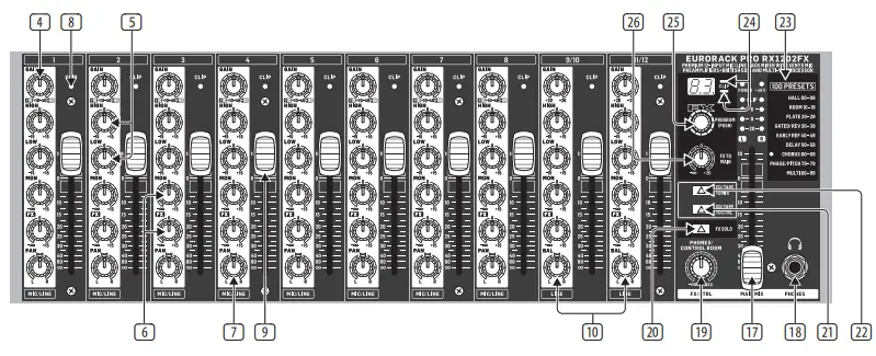
Controls
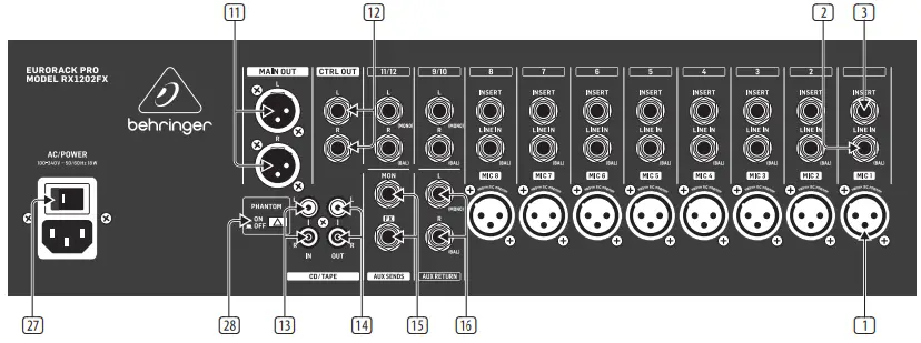
- MIC — Each mono input channel offers a balanced microphone input via the XLR connector and also features a switchable +48 V phantom power supply for condenser microphones.
- LINE IN — Each mono input also features a balanced line input on a 1/4″ connector.Unbalanced devices (mono connectors) can also be connected to these inputs.
- The INSERT connector is input and output at the same time. This allows you to insert external signal processors (compressors, gate, etc.)in the channel. The signal retrieval occurs after the TRIM and is practically a diversion of the signal. The input signal of the connected signal processor is diverted, processed and led back to the channel for further processing.
- Use the GAIN control to adjust the input gain.This control should always be turned fully counterclockwise whenever you connect or disconnect a signal source to one of the inputs.
- HIGH/LOW — All mono input channels include a 2-band equalizer. All bands provide a boost or cut of up to 15 dB. In the central position, the equalizer is inactive.The upper (HIGH) and the lower band (LOW) are shelving filters that increase or decrease all frequencies above or below their cut-off frequency. The cut-off frequencies of the upper and lower band are 12 kHz and 100 Hz respectively.
- MON/FX — FX sends buses (or AUX send buses) enable you to extract signals from one or more channels and collect these on a bus. You can retrieve the signal at the send connector to direct it to an external effects device, for example. The AUX return input is used as the return path. The send buses of the RX1202FX are mono buses.As the name suggests, the FX sends of the EURORACK mixing consoles are intended to drive effects devices (reverb, delay, etc.) and are therefore configured post-fader. This means that the mix between dry signal and effect remains at the level determined by the channel’s aux send, irrespective of the channel fader setting.If this were not the case, the effects signal of the channel would remain audible even when the fader is lowered to zero.In the RX1202FX, the FX send is routed directly to the built-in effects processor. To make sure that the effects processor receives an input signal, you shouldn’t turn this control all the way to the left (-∞).The MON path — as the name already implies — is meant to be used as a monitor signal path.For this application, it is important that the controller works as a pre-fader, which means it does not rely on the fader position. For this reason, the AUX send path is unsuitable for the connection to effects devices. By using the MON controller, you can produce a mono mix of individual signals that can be routed over the MON plug, located on the backside, to a headphones amplifier (e.g. MINI AMP AMP800) or a power amplifier for monitoring.
- The PAN control determines the position of the channel signal within the stereo image.This control features a constant-power characteristic, which means the signal is always maintained at a constant level, irrespective ofposition in the stereo panorama.
- The CLIP LEDs of the channels illuminate when the input signal is driven too high, which could cause distortion. If this happens, use the GAIN control to reduce the preamp level until the LED does not light anymore.
- The CHANNEL FADER determines the level of the channel signal in the Main Mix.
- The BAL(ANCE) control determines the levels of the left and right input signals relative to each other before both signals are then routed to the main stereo mix bus. If a channel is operated in mono via the left line input, this control has the same function as the PAN control used in the mono channels.
- The MAIN OUT connectors are balanced and laid out as XLR connectors. Here the summed signal of the main mix has a level of 0 dBu.
- The CTRL OUT connectors are used for controlling the summed signal (effects mix and main mix) as well as for individual signalsover studio monitor speakers. By using the PHONES/CONTROL ROOM controller in the main section, you can control the level ofboth outputs.
- The CD/TAPE INs are used to bring an external signal source (e.g. CD player, tape deck, etc.)into the console. They can also be used as a standard stereo line input, so the output of a second EURORACK or BEHRINGER ULTRALINK PRO MX882 can be connected. Alternatively, the line or tape output of a hi-fi amplifier with a source selection switch could also be hooked up here, allowing you to easily listen to additional sources (e.g. cassette recorder, minidisc player, sound card, etc.).
- CD/TAPE OUT — These connections are laid out as RCA connectors and are wired parallel to MAIN OUT. Connect the inputs of a computer sound card or a recorder here. The output signal level is set up using the highly accurate MAIN MIX fader.
- AUX SENDS — The FX connector routes the signal, which you have extracted from the individual channels by using the FX controller; the MON plug does the same to the signal that has been extracted by using the MON controller. Connect the input of an external effects processor to the FX plug, with which you want to modify the signal sum of the FX bus.Then, route the effects signal back to the mixer over the AUX RETURN connectors. With the MON outputs, you can connect an amplifier/ headphones amplifier for the musicians to monitor.
- AUX RETURN — You can connect the outputs of an external effects device to the AUX RETURN connectors. In this case, the effects signal is routed directly to the main mix bus and is then mixed with the “dry” signal. It is also possible to route the effects signal as mono by using the L connector.
- Use the MAIN MIX fader to adjust the volume of the main out.
- PHONES — The connector is used to connect a pair of headphones.The volume level is changed with the PHONES/CONTROL ROOM controller.
- Use the PHONES/CONTROL ROOM control to adjust the signal level of the CTRL OUT and PHONES outputs.
- FX SOLO — If you want to only listen to the effects signal with your headphones or monitor speakers, then press the FX SOLOswitch. The signal of the effects device can then be heard individually; the main mix or CD/tape signal is inaudible at the PHONESand CTRL OUT outputs.
- CD/TAPE TO CTRL — Press the CD/TAPE TO CTRL switch if you want to monitor the CD/ TAPE IN via the CTRL OUT and PHONES outputs.A typical studio application of this function is recording music into a digital audio workstation (DAW) with simultaneous reproduction.
- When the CD/TAPE TO MIX switch is pressed, the CD/tape input is assigned to the main mix providing additional input for tape machines, MIDI instruments or other signal sources that do not require any processing.
- 100 FIRST-CLASS EFFECTS — The EURORACK RX1202FX features a built-in digital stereo effects processor. This effects processor offers a large number of standard effects such as Hall, Chorus, Flanger, Delay, and various combination effects. Using the FX control, you can feed signals into the effects processor. The integrated effects module has the advantage of requiring no wiring. This way, the danger of creating ground loops or uneven signal levels is eliminated at the outset, completely simplifying the handling.
- The SIG LED on the effects module shows the presence of a signal whose level is high enough. This LED should always be on. However, make sure that the CLIP LED lights up only sporadically. If it is lit constantly, you are overdriving the effects processor, which leads to unpleasant distortion. If this occurs, turn the FX controls down somewhat.
- The PROGRAM control has two functions: by turning the PROGRAM control, you dial the number of an effect. The number of thepreset you just dialed up blinks in the display.To confirm your selection, press the PROGRAM control; the blinking stops.
- By using the FX TO the MAIN controller, the effects signal is sent to the main mix. No effects signal is to be heard in the summed signal of the mixer when the controller is positioned entirely to the left. Choose this position if you want to use an external effects device for the FX output.
- Use the POWER switch to turn on the mixing console. The POWER switch should always be in the “Off” position when you are about to connect your unit to the mains.
- The PHANTOM switch activates the phantom power (necessary to operate condenser microphones) on the XLR sockets of the mono channels. The red +48 V LED illuminates when phantom power is on. As a rule, dynamic microphones can still be used withphantom power, provided that they are wired in a balanced configuration. In case of doubt, contact the microphone manufacturer!
Specifications
| Inputs | |
| Mic inputs | |
| Type | XLR, electronically balanced |
| Impedance | 2.6 kΩ balanced |
| Max. input level | +12 dBu @ +10 dB gain |
| Gain range | +10 to +60 dB |
| Signal-to-noise ratio | -110 dB / -112 dB A-weighted |
| Distortion (THD + N) | 0.003%, A-weighted |
| Line inputs | |
| Type | 1/4″ TRS connector, electronically balanced |
| Impedance | 20 kΩ balanced, 10 kΩ unbalanced |
| Gain range | -10 to +40 dB |
| Max. input level | +22 dBu @ 0 dB gain |
| Auxiliary inputs | |
| Type | RCA connectors, unbalanced |
| Impedance | 20 kΩ |
| Max. input level | +22 dBu |
| Insert | |
| Type | 1/4″ TRS connector (tip = send, ring = return) |
| Aux return | |
| Type | 1/4″ TRS connector, balanced |
| Impedance | 20 kΩ balanced, 10 kΩ unbalanced |
| Max. input level | +22 dBu |
| Outputs | |
| Main out | |
| Type | XLR connectors, balanced |
| Impedance | 240 Ω balanced, 120 Ω unbalanced |
| Max. output level | +28 dBu balanced, +22 dBu unbalanced |
| Ctrl out | |
| Type | 1/4″ TRS connector, impedance balanced |
| Impedance | 240 Ω balanced, 120 Ω unbalanced |
| Max. output level | +22 dBu |
| CD/tape out | |
| Type | RCA connectors, unbalanced |
| Impedance | 1 kΩ |
| Max. output level | +22 dBu |
| Phones out | |
| Type | 1/4″ TRS connector, stereo |
| Max. output level | +19 dBu / 150 Ω (316 mW) |
| Aux send | |
| Type | 1/4″ TRS connector, impedance balanced |
| Impedance | 240 Ω balanced, 120 Ω unbalanced |
| Max. output level | +22 dBu |
| EQ | |
| Low | ±15 dB @ 100 Hz |
| High | ±15 dB @ 12 kHz |
| System Specifications | |
| Noise | |
| Main mix @ -∞,channel fader @ -∞ | -98 dB / -101 dB A-weighted |
| Main mix @ 0 dB,channel fader @ -∞ | -85 dB / -88 dB A-weighted |
| Main mix @ 0 dB,channel fader @ 0 dB | -77 dB / -80 dB A-weighted |
| Frequency response | 20 Hz to 105 kHz, ±1 dB |
| Crosstalk | 90 dB |
| Effects Section | |
| Converter | 24-bit Sigma-Delta |
| Frequency rate | 40 kHz |
| Presets | 100 |
| Power Supply | |
| Switch-mode autorange power supply | 100-240 V ~50/60 Hz |
| Power consumption | 18 W |
| Mains connection | Standard IEC connector |
| Physical | |
| Dimensions(H x W x D) | 133 x 482 x150 mm (5.2 x19.0 x 5.9″) |
| Weight | 3.1 kg (6.8 lbs) |
Important information
- Register online. Please register your new Music Tribe equipment right after you purchase it by visiting behringer.com. Registering your purchase using our simple online form helps us to process your repair claims more quickly and efficiently. Also, read the terms and conditions of our warranty, if applicable.
- Malfunction. Should your Music Tribe Authorized Reseller not be located in your vicinity, you may contact the Music Tribe Authorized Fulfiller for your country listed under “Support” at behringer.com. Should your country not be listed, please check if yourthe problem can be dealt with by our “Online Support” which may also be found under “Support” at behringer.com.Alternatively, please submit an online warranty claim at behringer.com BEFORE returning the product.
- Power Connections. Before plugging the unit into a power socket, please make sure you are using the correct mains voltage for your particular model.Faulty fuses must be replaced with fuses of the same type and rating without exception.
FEDERAL COMMUNICATIONSCOMMISSION COMPLIANCEINFORMATION
BehringerRX1202FX
| Responsible Party Name: | Music Tribe Commercial NV Inc. |
| Address: | 901 Grier DriveLas Vegas, NV 89118USA |
| Phone Number: | +1 702 800 8290 |
RX1202FXcomplies with the FCC rules as mentioned in the following paragraph:This equipment has been tested and found to comply with the limits for a Class B digital device, pursuant to part 15 of the FCC Rules. These limits are designed to provide reasonable protection against harmful interference in a residential installation. This equipment generates, uses, and can radiate radio frequency energy and, if not installed and used in accordance with the instructions, may cause harmful interference to radio communications. However, there is no guarantee that interference will not occur in a particular installation. If this equipment does cause harmful interference to radio or television reception, which can be determined by turning the equipment off and on, the user is encouraged to try to correct the interference by one or more of the following measures:
- Reorient or relocate the receiving antenna
- Increase the separation between the equipment and receiver
- Connect the equipment into an outlet on a circuit different from that to which the receiver is connected
- Consult the dealer or an experienced radio/TV technician for helpThis device complies with Part 15 of the FCC rules. Operation is subject to the following two conditions:
- this device may not cause harmful interference, and
- this device must accept any interference received, including interference that may cause undesired operation.
Important information:Changes or modifications to the equipment not expressly approved by Music Tribe can void the user’s authority to use the equipment.
We Hear You
report this ad![]()
References
[xyz-ips snippet=”download-snippet”]