![]()
Quick Start Guide
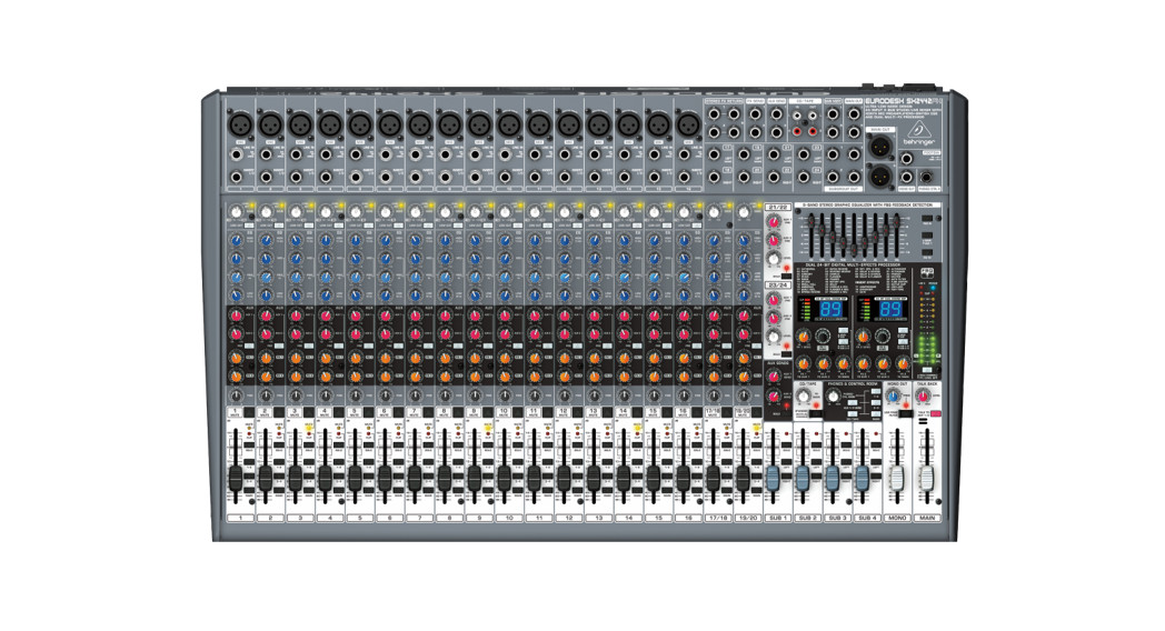
 EURODESK SX3242FX/SX2442FX
Ultra-Low Noise Design 24-Input 4-Bus Studio/Live Mixer withXENYX Mic Preamplifiers, British EQs, and Dual Multi-FX ProcessorV 7.0
Important Safety Instructions
 Terminals marked with this symbol carry an electrical current of sufficient magnitude to constitute a risk of electric shock. Use only high-quality professional speaker cables with ¼” TS or twist-locking plugs pre-installed. All other installation or modifications should be performed only by qualified personnel.
This symbol, wherever it appears, alerts you to the presence of uninsulated dangerous voltage inside the enclosure – voltage that may be sufficient to constitute a risk of shock.
![]() This symbol, wherever it appears, alerts you to important operating and maintenance instructions in the accompanying literature. Please read the manual.
This symbol, wherever it appears, alerts you to important operating and maintenance instructions in the accompanying literature. Please read the manual.
Caution![]() To reduce the risk of electric shock, do not remove the top cover (or the rear section). No user-serviceable parts inside. Refer servicing to qualified personnel.
To reduce the risk of electric shock, do not remove the top cover (or the rear section). No user-serviceable parts inside. Refer servicing to qualified personnel.
Caution![]() To reduce the risk of fire or electric shock, do not expose this appliance to rain and moisture. The apparatus shall not be exposed to dripping or splashing liquids and no objects filled with liquids, such as vases, shall be placed on the apparatus.
To reduce the risk of fire or electric shock, do not expose this appliance to rain and moisture. The apparatus shall not be exposed to dripping or splashing liquids and no objects filled with liquids, such as vases, shall be placed on the apparatus.
Caution![]() These service instructions are for use by qualified service personnel only. To reduce the risk of electric shock do not perform any servicing other than that contained in the operation instructions. Repairs have to be performed by qualified service personnel.
These service instructions are for use by qualified service personnel only. To reduce the risk of electric shock do not perform any servicing other than that contained in the operation instructions. Repairs have to be performed by qualified service personnel.
- Read these instructions.
- Keep these instructions.
- Heed all warnings.
- Follow all instructions.
- Do not use this apparatus near water.
- Clean only with a dry cloth.
- Do not block any ventilation openings. Install in accordance with the manufacturer’s instructions.
- Do not install near any heat sources such as radiators, heat registers, stoves, or other apparatus (including amplifiers) that produce heat.
- Do not defeat the safety purpose of the polarized or grounding-type plug. A polarized plug has two blades with one wider than the other. A grounding-type plug has two blades and a third grounding prong. The wide blade or the third prong are provided for your safety. If the provided plug does not fit into your outlet, consult an electrician for the replacement of the obsolete outlet.
- Protect the power cord from being walked on or pinched particularly at plugs, convenience receptacles, and the point where they exit from the apparatus.
- Use only attachments/accessories specified by the manufacturer.

- Use only with the cart, stand, tripod, bracket, or table specified by the manufacturer, or sold with the apparatus. When a cart is used, use caution when moving the cart/apparatus combination to avoid injury from tip-over.
- Unplug this apparatus during lightning storms or when unused for long periods of time.
- Refer all servicing to qualified service personnel. Servicing is required when the apparatus has been damaged in any way, such as power supply cord or plug is damaged, liquid has been spilled or objects have fallen into the apparatus, the apparatus has been exposed to rain or moisture, does not operate normally, or has been dropped.
- The apparatus shall be connected to a MAINS socket outlet with a protective earthing connection.
- Where the MAINS plug or an appliance coupler is used as the disconnect device, the disconnect device shall remain readily operable.
- Correct disposal of this product: This symbol indicates that this product must not be disposed of with household waste, according to the WEEE Directive (2012/19/EU) and your national law. This product should be taken to a collection center licensed for the recycling of waste electrical and electronic equipment (EEE). The mishandling of this type of waste could have a possible negative impact on the environment and human health due to potentially hazardous substances that are generally associated with EEE. At the same time, your cooperation in the correct disposal of this product will contribute to the efficient use of natural resources. For more information about where you can take your waste equipment for recycling, please contact your local city office or your household waste collection service.
- Do not install in a confined space, such as a bookcase or similar unit.
- Do not place naked flame sources, such as lighted candles, on the apparatus.
- Please keep the environmental aspects of battery disposal in mind. Batteries must be disposed of at a battery collection point.
- This apparatus may be used in tropical and moderate climates up to 45°C.


LEGAL DISCLAIMER
Music Tribe accepts no liability for any loss which may be suffered by any person who relies either wholly on or in part upon any description, photograph, or statement contained herein. Technical specifications, appearances, and other information are subject to change without notice. All trademarks are the property of their respective owners. Midas, Klark Teknik, Lab Gruppen, Lake, Tannoy, Turbosound, TC Electronic, TC Helicon, Behringer, Bugera, Oberheim, Auratone, and Coolaudio are trademarks or registered trademarks of Music Tribe Global Brands Ltd. © Music Tribe Global Brands Ltd. 2021 All rights reserved.
LIMITED WARRANTY
For the applicable warranty terms and conditions and additional information regarding Music Tribe’s Limited Warranty, please see complete details online at musictribe.com/warranty.
EURODESK SX3242FX/SX2442FX Controls
 |
 |
 |
 |
 |
|
Controls
- Each mono input channel is equipped with a balanced microphone input on an XLR connector, which provides +48 V phantom power for condenser microphones at the touch of a button (see rear panel).
- Each mono input also has a balanced line input on ¼” TRS connectors. Of course, these inputs can also be used with unbalanced plugs (¼” TS connector).
- The INSERT I/O connector is used to process a signal with dynamic processors or equalizers. This insert point is prefader, pre-EQ and pre-aux send.
- The GAIN control adjusts the input gain. Be sure to set this control fully counter-clockwise before you connect or disconnect a signal source to or from one of the inputs.
- Mono channels are equipped with a high-slope LOW CUT filter eliminating unwanted low-frequency signals, such as floor rumble (18 dB/oct., -3 dB at 80 Hz).
- The HIGH control in the EQ section controls the high frequency range of the respective channel. It is a shelving-type filter which can boost or cut all frequencies above a fixed frequency (12 kHz).
- The MID control allows you to raise or lower the mid-range level. It is a semi-parametric peak filter, which boosts or cuts the frequency range around a variable mid-range frequency. Use the FREQ control to select the mid-range frequency from 100 Hz to 8 kHz. Then use the MID control to boost or cut the selected frequency range.
- The LOW control boosts or cuts the low-frequency range. Like the HIGH filter it is a shelving-type filter, which raises or lowers the level of all frequencies below a specific frequency (80 Hz).
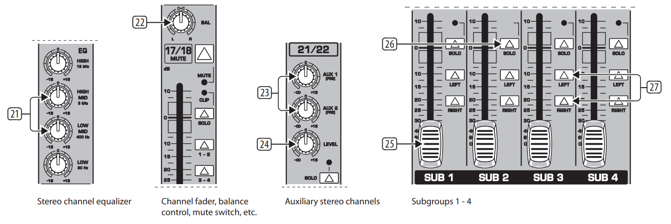
- On each channel, the AUX 1 and AUX 2 controls allow you to determine the level of the aux signals sent from the channel. The main aux send signal comprising the aux send signals from all channels can then be adjusted with the corresponding master AUX SEND controls (51), and is present at the AUX SEND outputs (52). Both aux sends are mono, post-EQ, with a gain of up to +15 dB.
- Press the PRE switch to set all aux sends to pre-fader. In this case, the volume of the aux signals is no longer dependent on the fader position, so you can create completely independent monitor mixes.
- FX 1 and FX 2 controls provide a direct route to the built-in effects processor. Additionally, they can be used to control an external effects unit, via the FX SEND 1 and 2 outputs (similar to the AUX SEND 1 and 2 jacks). To ensure that the internal effects processor and theFX SEND outputs actually get a signal, the corresponding FX control must not be set fully counter-clockwise (-∞), and the master FX SEND (see (60)) must be turned up. The FX buses are hard-wired post-fader.
- The PAN control determines the position of the channel signal in the stereo mix as well as the subgroup to which the channel signal is routed.
- Use the MUTE switch to mute the channel signal, so it is no longer part of the main mix. At the same time, all aux buses set to post-fader are muted for the respective channel, while the pre-fader monitor buses remain operative. The MUTE LED is illuminated when the channel is muted.
- The CLIP LED illuminates when the channel overloads. In this case, please reduce the input gain using the GAIN control. This LED also illuminates when you activate the solo function with the SOLO switch below.
- The SOLO switch routes the channel signal to the solo bus (Solo In Place) or the PFL bus (Pre Fader Listen). Thus, you can monitor a channel signal without affecting the main output signal. The signal to be monitored is taken either pre (PFL, mono) or post-panorama control(Solo, stereo) and post-channel fader (depending on the position of the SOLO/PFL switch (40)).
- The SUB switch routes the signal to the respective subgroups. Your EURODESK features 4 subgroups (1-2 and 3-4). With the PAN control on the input channel (see (12)) you can determine to which of the two groups the signal is routed (hard left: sub 1 or 3, hard-right: sub 2 or 4).
- The MAIN switch routes the signal to the main mix. The channel fader governs the level of the channel signal as part of the main mix (or submit).
- Each stereo channel is equipped with two balanced line-level inputs on ¼” TRS connectors for the left and right channels. The channels can also process mono signals, as long as you use the “LEFT” jack only.
- All stereo channel strips have a GAIN control for gain adjustment. Its scale ranges from +20 to -20 dB and allows you to adapt the input level to the line inputs.
- The stereo channels are equipped with a stereo equalizer. The filter types and cutoff frequencies for HIGH and LOW filters are the same as on the mono channels. Instead of one semi-parametric midrange band, the stereo channels have two separate midrange bands
- (HIGH MID and LOW MID) with fixed mid-frequencies (3 kHz and 400 Hz). Stereo EQs are preferable for processing the frequency response of stereo signals. With two mono equalizers, you might encounter problems with different settings between the left and right channels.
- The BAL(ANCE) control has the same function as the PAN control on the mono channels. It determines the relative volume of the left and right input signals before they are routed to the stereo main mix bus (or to two subgroups). (23) +
- +
- Your EURODESK has two stereo channels with an aux send section (AUX 1 and AUX 2) and one LEVEL control. For these channels, the aux buses are hard-wired to pre-fader and are therefore particularly useful for monitoring. They have no routing switches and are always sent to the main mix. Like the normal stereo channels, they have two line-level inputs on ¼” TRS connectors for the left and right channels, and aSOLO switch.
- The subgroup faders determine the volume of the subgroup signal at the subgroup output (28). Depending on the position of the routing switch (27) you can thus control the subgroup volume in the main mix.
- The SOLO switch routes the subgroup signal to the solo bus (Solo In Place) or PFL bus (Pre Fader Listen), so that you can monitor the subgroup signal without affecting the main or sub output signals. The signal to be monitored is taken either pre (PFL, mono) or postsubgroup fader (Solo, stereo), depending on the position of the SOLO/PFL switch (40)). The SOLO LED illuminates when the SOLO switch is pressed.
- Use the routing switches for the subgroups to send the subgroup signal to the main mix. You can route it to the left stereo side (=LEFT pressed), to the right stereo side (=RIGHT pressed) or to both (=LEFT and RIGHT pressed). For example, when you have created a stereo submit using subgroups 1 and 2, be sure to route group 1 to the left and group 2 to the right side to maintain proper stereo positioning. If it is a mono submix with just one subgroup, route it to the left and right sides of the main mix to make the signal audible on both sides.
- These four SUBGROUP OUT (puts) carry the signals of the individual subgroups. For multi-tracking connect the outputs to the inputs of a multi-track recorder.
- The MONO fader controls the volume of the signal present at the MONO OUT (see (32)).
- The FREQ control adjusts the cut-off frequency of the low-pass filter (30 to 200 Hz). Frequencies above the cut-off are filtered out when activated.
- Use the LOW PASS FILTER switch to activate the filter function (LED illuminates).
- The MONO OUT connector provides the line-level mono signal for connection to the inputs of a power amp or active speaker. You can also use this output as a monitor bus, e.g. to connect a headphone amplifier. In this case, the signal should of course not be limited by the low-pass filter.
- Use this high-precision MAIN fader to control the output level of the main mix.
- The MAIN OUT(puts) are balanced XLR connectors with a nominal operating level of +4 dBu and provide the main mix signal.
- The MAIN OUT ¼” TRS connectors outputs also provide the main mix signal.
- Like the channel inserts, the MAIN INSERT connectors can be used to connect a dynamics processor or equalizer for further processing of the mix signal. The MAIN INSERT refers to the Main Outs (XLR and ¼” TRS connectors), the MONO OUT (see (32) ) and, if the MAIN switch in the PHONES/CONTROL ROOM section is pressed, also to the PHONES/CTRL ROOM output (see (46) ).
- The red “+48 V” LED illuminates when phantom power is on. Phantom power is required for the operation of condenser microphones and can be switched on with the corresponding switch on the rear of the console.
- The POWER LED is illuminated when the console is switched on.
- The high-precision level meter accurately indicates the output signal level. For example, when you press the SOLO switch on one of the input channels, its signal level will be displayed here, either pre-fader (PFL) or post-fader (SOLO), depending on the position of the SOLO/ PFL switch (see (40)). In PFL mode only the left display is active because the PFL signals are mono.
- The SOLO/PFL switch determines whether the monitored signal is pre (PFL) or post-fader (SOLO) after pressing the SOLO/PFL switch (the LED illuminates). The level meter indicates the corresponding signal (see (39) ). When you adjust a signal with the GAIN control, it is advisable to select PFL mode, so that the level shown is independent of the channel fader position.
- The LEVEL control determines the volume of the talkback signal at the AUX 1/2 outputs.
- Use the TALK TO AUX 1/2 switch to activate the built-in talkback microphone. Its signal is sent to the AUX SEND jacks 1 and 2. Keep the switch pressed while you’re speaking.
- This is the built-in talkback microphone.
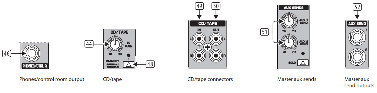
- The PHONES/CTRL R control adjusts the volume of the headphones connected to the PHONES/ CTRL ROOM OUT jack (see (46)). If you have an active monitor speaker or power amp connected here, you can also control the monitor volume.
- These switches select the signal sent to the PHONES/ CTRL ROOM jack. Available sources are MAIN, CD/TAPE, AUX 1/2 and subgroups 1 – 2 and 3 – 4.
- Connect your headphones or monitor speaker to the PHONES/CTRL ROOM OUT ¼” TRS connector.
- TO MAIN controls the volume of, for example, a CD player connected to the CD/tape input connectors (see (49)).
- When the STANDBY switch is pressed, all input channels are muted. Only the CD/tape signal will be routed to the main mix. In this way, you can prevent the microphones from picking up unwanted sounds or noise that would interfere with CD playback during a break. The main mixand channel faders can remain in their normal positions while playing back music from CD (using the CD/ TAPE INPUTs (49)), so you don’t lose your mix.
- The CD/TAPE INPUT RCA connectors are for the connection of CD players, tape decks, or other line-level sources. The signal volume is adjusted with the TO MAIN control.
- The CD/TAPE OUTPUT RCA connectors provide the stereo main mix signal to a tape deck or DAT recorder to record your mix. The signal is taken pre-fader so that it will not be influenced by the fader positions.
- These are the master AUX SEND controls 1 and 2 for adjusting the volume level sent to the corresponding aux send connectors (see (52)). This way, you can control the mix of all AUX 1 or AUX 2 signals of the input channels. The AUX SEND section also has a SOLO switch.
- Use the AUX SEND outputs 1 and 2 to take the master AUX SEND signals and route them to external effects device or your monitor speakers. Subsequently, you can return the effect signal, e.g. via the STEREO FX RETURN inputs (see (67)) or specific input channels.
- Your EURODESK is equipped with a graphic 9-band stereo equalizer processing either the main or the AUX 1 signal. Use the EQ to adapt the sound to the room acoustics.
- Use the EQ IN switch to switch the equalizer on. In this case, the fader LEDs illuminate.
- With the MAIN/AUX 1 switch you can determine the signal to be processed, either main or AUX 1.
- Press the FBQ In switch to activate the FBQ Feedback Detection System. The frequencies causing feedback are indicated by the brightly lit fader LEDs, while all other LEDs are darker. Simply lower the level of the brightly lit faders until feedback disappears.
- Here you will find a list of all multi-effects presets.
- The FX LED level meters show the effects processor’s input signal. Be sure that the clip LED only illuminates signal peaks. If it is lit all the time, the effects processor is overloading and hence producing unpleasant distortion.
- The EFFECT displays show the currently selected presets.
- This is the master FX 1 (or 2) SEND control for adjusting the volume of all FX send signals at the corresponding FX send jacks (see (66)) and at the inputs of the built-in effects processor. Use it to control the master signal of all FX 1/FX 2 signals from the input channels. When neither of the FX SEND controls is turned up, the effects processor will not receive a signal.
- Turn the FX 1 (or FX 2) control to select effects preset. Then, push it briefly to confirm your selection and activate the new effect.
- The FX 1 (or 2) TO AUX 1 controls allow you to add the effect signal from the built-in effects processor (FX1 or FX2) to the AUX 1 monitor signal. Naturally, the effects processor must be provided with an input signal (i.e. the FX controls in the channel strips plus the FX SEND controls and the channel faders must be turned up).
- This is the FX 1 (or 2) TO AUX 2 control adding the effect signal from the effects processor to the AUX 2 monitor signal. See (62) for further details.
- The FX 1 (or 2) TO MAIN control routes the effect signal either to the main mix or the subgroups 1 and 2 (or 3 and 4), depending on the position of the selector switch (see (65)). When it is hard left, no effect signal will be audible. Here, too, the FX controls in the channel stripsplus the FX SEND controls and the channel faders must be turned up.
- These selector switches route the effect signal to the main mix or to the subgroups 1-2 or 3-4. If the MAIN/SUB switch is not pressed, the effect signal is sent to the main mix and the SUB 1/2 / SUB 3/4 switch below is inoperative. If the upper switch is pressed (SUB),however, the lower switch determines whether the effect signal is routed to subgroups 1 and 2 (SUB 1/2) or 3 and 4 (SUB 3/4).
- The FX SEND 1 and 2 connectors also provide the master FX send signals, for example, to connect them to the inputs of an external effects device. However, these are “dry” signals only with no “effect signals” from the built-in effects processor!
- The Stereo FX RETURN inputs 1 and 2 return the effect signals from external effects processors and add them to the main mix.
- The FOOTSW(ITCH) connector allows you to connect a standard dual footswitch to separately enable/ disable FX 1 or FX 2. The tip of the ¼” plug controls FX 1, the ring controls FX 2.
- Use the POWER switch to put the mixer into operation. This switch should always be in the “Off” position when you connect your unit to the mains.
- With the PHANTOM switch, you can activate the phantom power supply for the XLR connectors of the mono channels for condenser microphones. The +48 V-LED (37) illuminates when phantom power is on. In most cases, dynamic microphones can still be used as long as they are connected in a balanced configuration. If in doubt, please contact the manufacturer of your microphone!
- The mains connection is a standard IEC receptacle. An appropriate power cord is supplied with the unit.
- FUSE HOLDER.
- SERIAL NUMBER.
Specifications
|
Mono Inputs |
SX3242FX |
SX2442FX |
| Microphone inputs (XENYX Mic preamp) | ||
| Type | XLR connector, electronically balanced, discrete input circuit | |
| Mic E.I.N. (20 Hz – 20 kHz) | ||
| @ 0 Ω source resistance | -134 dB / 135.7 dB A-weighted | |
| @ 50 Ω source resistance | -131 dB / 133.3 dB A-weighted | |
| @ 150 Ω source resistance | -129 dB / 130.5 dB A-weighted | |
| Frequency Response | ||
| <10 Hz – 160 kHz | -1 dB | |
| <10 Hz – 200 kHz | -3 dB | |
| Gain range | +10 dB to +60 dB | |
| Max. input level | +12 dBu @ +10 dB GAIN | |
| Impedance | approx. 2.6 kΩ balanced | |
| Signal-to-noise ratio | 110 dB / 112 dB A-weighted (0 dBu In @ +22 dB GAIN) | |
| Distortion (THD + N) | 0.005 % / 0.004 % A-weighted | |
| Line Input | ||
| Type | ¼” TRS jack, electronically balanced | |
| Impedance | approx. 20 kΩ balanced, approx. 10 kΩ unbalanced | |
| Gain range | -10 dB to +40 dB | |
| Max. input level | +22 dBu @ 0 dB GAIN | |
| Fade-Out Attenuation (Crosstalk Attenuation) | ||
| Main fader closed | 90 dB | |
| Channel muted | 84 dB | |
| Channel fader muted | 85 dB | |
| Frequency response (Mic In ➝ Main Out) | ||
| <10 Hz – 90 kHz | +0 dB / -1 dB | |
| <10 Hz – 160 kHz | +0 dB / -3 dB | |
| Stereo Inputs | ||
| Type | 2 x ¼” TRS jack, balanced | |
| Impedance | approx. 20 kΩ balanced, approx. 10 kΩ unbalanced | |
| Gain range | -20 dB to +20 dB | |
| Max. input level | +22 dBu @ 0 dB GAIN | |
| CD/Tape In | ||
| Type | RCA connector | |
| Impedance | approx. 10 kΩ | |
| Max. input level | +22 dBu | |
| Equalizer | ||
| EQ Mono Channels | ||
| LOW | 80 Hz / ±15 dB | |
| MID | 100 Hz to 8 kHz / ±15 dB | |
| HIGH | 12 kHz / ±15 dB | |
| LOW CUT | 80 Hz, 18 dB/oct. | |
| EQ Stereo Channels | ||
| LOW | 80 Hz / ±15 dB | |
| LOW MID | 500 Hz / ±15 dB | |
| HIGH MID | 3 kHz / ±15 dB | |
| HIGH | 12 kHz / ±15 dB | |
| Main Outputs (XLR) | ||
| Type | XLR connector, electronically balanced | |
| Impedance | approx. 240 Ω balanced, approx. 120 Ω unbalanced | |
| Max. output level | +28 dBu | |
| Main Outputs (¼”) | ||
| Type | ¼” TRS jack, electronically balanced | |
| Impedance | approx. 240 Ω balanced, approx. 120 Ω unbalanced | |
| Max. output level | +28 dBu | |
| Main Inserts | ||
| Type | ¼” TRS jack, unbalanced | |
| Max. input level | +22 dBu | |
| Mono Output | ||
| Type | ¼” mono jack, unbalanced | |
| Impedance | approx. 120 Ω | |
| Max. output level | +22 dBu | |
| Low pass | variable, 30 Hz to 200 Hz, 18 dB/oct. | |
| Phones/CTRL Room Output | ||
| Type | ¼” TRS jack, unbalanced | |
| Max. output level | +19 dBu / 150 Ω (+25 dBm) | |
| CD/Tape Out | ||
| Type | RCA connector | |
| Impedance | approx. 1 kΩ | |
| Max. output level | +22 dBu | |
| DSP | ||
| Type | Texas Instruments | |
| Converter | 24-bit delta-sigma, 64/128-times oversampling | |
| Sampling rate | 46 kHz | |
| Main Mix System Data (Noise) | ||
| Main mix @ -∞,
channel fader @ -∞ |
-100 dB / -102.5 dB A-weighted | |
| Main mix @ 0 dB,
channel fader @ -∞ |
-82 dB / -85 dB A-weighted | |
| Main mix @ 0 dB,
channel fader @ 0 dB |
-72 dB / -75 dB A-weighted | |
| Power Supply | ||
| Power consumption | 50 W | |
| Fuse (100 – 240 V~, 50/60 Hz) | T 2,0 A H 250 V | |
| Mains connector | Standard IEC receptacle | |
| Physical/Weight | ||
| Dimensions (H x W x D) | 100 x 896 x 410 mm
(3.9 x 35.3 x 16.1″) |
100 x 682 x 410 mm
(3.9 x 26.9 x 16.1″) |
| Weight (net) | 11.0 kg (24.3 lbs) | 8.6 kg (19 lbs) |
Important information
- Register online. Please register your new Music Tribe equipment right after you purchase it by visiting musictribe.com. Registering your purchase using our simple online form helps us to process your repair claims more quickly and efficiently. Also, read the terms and conditions of our warranty, if applicable.
- Malfunction. Should your Music Tribe Authorized Reseller not be located in your vicinity, you may contact the Music Tribe Authorized Fulfiller for your country listed under “Support” at musictribe.com. Should your country not be listed, please check if your problem can be dealt with by our “Online Support” which may also be found under “Support” at musictribe.com. Alternatively, please submit an online warranty claim at musictribe.com BEFORE returning the product.
- Power Connections. Before plugging the unit into a power socket, please make sure you are using the correct mains voltage for your particular model. Faulty fuses must be replaced with fuses of the same type and rating without exception.
FEDERAL COMMUNICATIONS COMMISSION COMPLIANCE INFORMATIONBehringerEURODESK SX3242FX/SX2442FX
| Responsible Party Name: | Music Tribe Commercial NV Inc. |
| Address: | 5270 Procyon Street, Las Vegas NV 89118, United States |
| Phone Number: | +1 702 800 8290 |
EURODESK SX3242FX/SX2442FXThis equipment has been tested and found to comply with the limits for a Class B digital device, pursuant to part 15 of the FCC Rules. These limits are designed to provide reasonable protection against harmful interference in a residential installation. This equipment generates, uses and can radiate radio frequency energy and, if not installed and used in accordance with the instructions, may cause harmful interference to radio communications. However, there is no guarantee that interference will not occur in a particular installation. If this equipment does cause harmful interference to radio or television reception, which can be determined by turning the equipment off and on, the user is encouraged to try to correct the interference by one or more of the following measures:
- Reorient or relocate the receiving antenna.
- Increase the separation between the equipment and receiver.
- Connect the equipment into an outlet on a circuit different from that to which the receiver is connected.
- Consult the dealer or an experienced radio/TV technician for help.
 report this ad
This equipment complies with Part 15 of the FCC Rules. Operation is subject to the following two conditions:
- This device may not cause harmful interference, and
- This device must accept any interference received, including interference that may cause undesired operation.
Important information:Changes or modifications to the equipment not expressly approved by Music Tribecan void the user’s authority to use the equipment. Hereby, Music Tribe declares that this product is in compliance with Directive2014/35/EU, Directive 2014/30/EU, Directive 2011/65/EU, and Amendment 2015/863/EU, Directive 2012/19/EU, Regulation 519/2012 REACH SVHC and Directive1907/2006/EC.Full text of EU DoC is available at https://community.musictribe.com/EU Representative: Music Tribe Brands DK A/SAddress: Ib Spang Olsens Gade 17, DK – 8200 Aarhus N, Denmark
[xyz-ips snippet=”download-snippet”]