User Guide
![]()
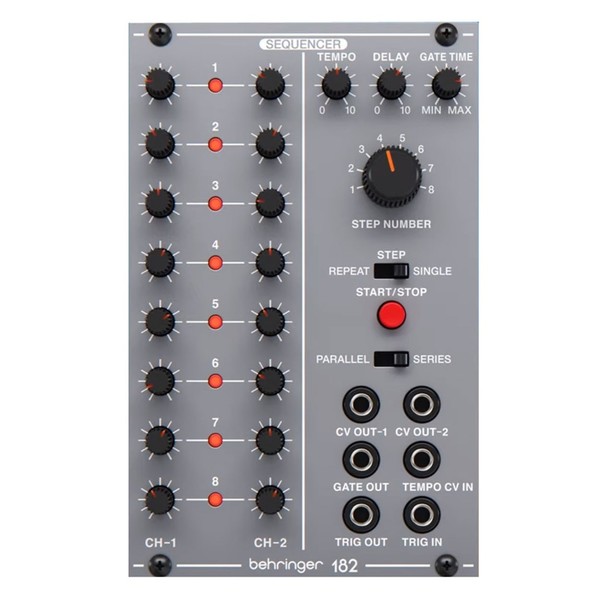
Behringer System 100 182 SEQUENCER
Legendary Analog Sequencer Module for Eurorack
Controls
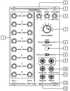
- CH-1/CH-2 SEQUENCER COLUMNS – Use the knobs to set the control voltage output for each step. Each column sends out control voltages over a dedicated output jack (CV OUT-1 and CV OUT-2). In PARALLEL mode, two independent voltages can be set for each step for a total of up to 8 steps. In SERIES mode, you can program sequences of up to 16 steps.
- TEMPO – This knob controls the step speed of the sequencer. The internal tempo clock can also be controlled via the TEMPO CV IN jack. You can also route control voltages from the CV OUT-1 or CV OUT-2 output jacks back into the clock via the TEMPO CV IN jack to program variable timing between each step.
- DELAY – Use this knob to set the amount of time taken (0 to 10 seconds) to shift to the sequence’s next step voltage, which is set by the 16 knobs in the CH-1/CH-2 SEQUENCER COLUMNS. The DELAY parameter creates an effect similar to a portamento effect, except with an exponential response. The DELAY function only operates on the CV OUT-1 output jack (in both PARALLEL and SERIES modes). The CV OUT-2 output jack is unaffected by the DELAY control.
- GATE TIME – This knob controls the length of time the GATE OUT control voltage is active – known as the “duty cycle” – in a range from 10% to 90%.
- STEP NUMBER – Rotate this knob to set the number of steps counted before the sequencer re-starts. In PARALLEL mode, the STEP NUMBER setting affects both columns simultaneously. In SERIES mode, the STEP NUMBER setting affects only the CH-2 row so that you may create longer sequences of 9 to 16 steps.
- STEP (REPEAT/SINGLE) – This sliding switch determines how the sequencer responds to triggering. In the REPEAT setting, the sequence repeats every time it reaches the end. The SINGLE setting stops the sequence after one full cycle. The middle STEP setting advances the sequence one step each time a trigger control voltage is received a the TRIG IN jack.
- START/STOP – Press this button to trigger or stop the sequence.
- PARALLEL/SERIES – This sliding switching determines whether each step of the CH-1 and CH-2 columns trigger separately and simultaneously (PARALLEL) for sequences of up 8 steps, or if the two columns trigger one after the other (SERIES) with the CH-1 column triggering first, followed by the CH-2 column. In SERIES mode, you can create sequences of 8 to 16 steps.
- CV OUT-1/CV OUT-2 – These jacks send out separate control voltage signals for the CH-1 (CV OUT-1 jack) and CH-2 (CV OUT-2 jack) columns. When in SERIES mode, CV OUT-1 provides the 16-step output and the CV OUT-2 jack provides an 8-step output.
- TEMPO CV IN – This jack routes in a control voltage signal to control the tempo clock.
- GATE OUT – This jack sends out a gate trigger signal for every sequencer step via cables with 3.5 mm connectors.
- TRIG IN – This input allows you to route in a trigger voltage via cables with 3.5 mm connectors.
- TRIG OUT – Use this jack to send out a trigger voltage signal for use with other modules. This trigger voltage is generated when the sequencer reaches its end step.
Power Connection
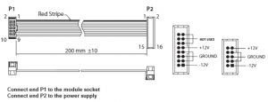
The 182 ANALOG SEQUENCER module comes with the required power cable for connecting to a standard Eurorack power supply system. Follow these steps to connect power to the module. It is easier to make these connections before the module has been mounted into a rack case.
- Turn the power supply or rack case power o and disconnect the power cable.
- Insert the 16-pin connector on the power cable into the socket on the power supply or rack case. The connector has a tab that will align with the gap in the socket, so it cannot be inserted incorrectly. If the power supply does not have a keyed socket, be sure to orient pin 1 (-12 V) with the red stripe on the cable.
- Insert the 10-pin connector into the socket on the back of the module. The connector has a tab that will align with the socket for correct orientation.
- After both ends of the power cable have been securely attached, you may mount the module in a case and turn on the power supply.
Installation
The necessary screws are included with the module for mounting in a Eurorack case. Connect the power cable before mounting.
Depending on the rack case, there may be a series of fixed holes spaced 2 HP apart along the length of the case, or a track that allows individual threaded plates to slide along the length of the case. The free-moving threaded plates allow precise positioning of the module, but each plate should be positioned in the approximate relation to the mounting holes in your module before attaching the screws.
Hold the module against the Eurorack rails so that each of the mounting holes are aligned with a threaded rail or threaded plate. Attach the screws part way to start, which will allow small adjustments to the positioning while you get them all aligned. After the final position has been established, tighten the screws down.
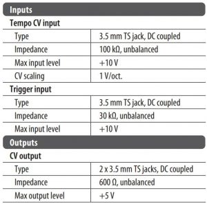
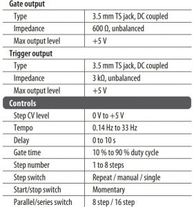
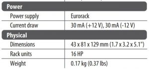
Specifications
LEGAL DISCLAIMER
Music Tribe accepts no liability for any loss which may be su ered by any person who relies either wholly or in part upon any description, photograph, or statement contained herein. Technical speci cations, appearances and other information are subject to change without notice. All trademarks are the property of their respective owners. Midas, Klark Teknik, Lab Gruppen, Lake, Tannoy, Turbosound, TC Electronic, TC Helicon, Behringer, Bugera, Auratone and Coolaudio are trademarks or registered trademarks of Music Tribe Global Brands Ltd. © Music Tribe Global Brands Ltd. 2020 All rights reserved.
LIMITED WARRANTY
For the applicable warranty terms and conditions and additional information regarding Music Tribe’s Limited Warranty, please see complete details online at musictribe.com/warranty.
![]()
behringer System 100 182 SEQUENCER User Guide – behringer System 100 182 SEQUENCER User Guide –
Questions about your Manual? Post in the comments!
[xyz-ips snippet=”download-snippet”]