![]() Quick Start Guide
Quick Start Guide
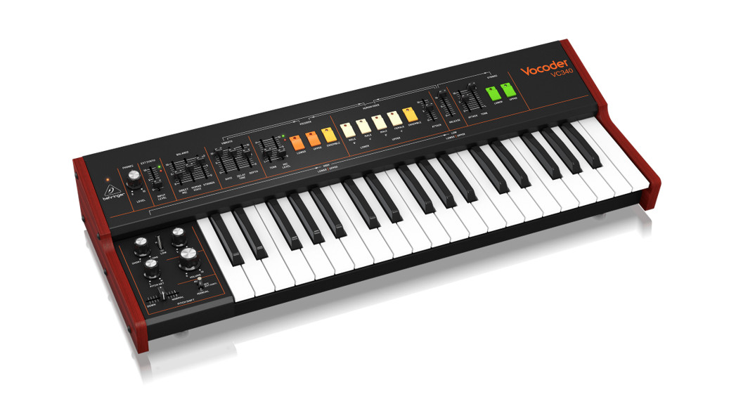
VOCODER VC340Authentic Analog Vocoder for Human Voice and Strings Ensemble Sounds from the ’80s
Important Safety Instructions
 Terminals marked with this symbol carry an electrical current of sufficient magnitude to constitute a risk of electric shock. Use only high-quality professional speaker cables with ¼” TS or twist-locking plugs pre-installed. All other installation or modifications should be performed only by qualified personnel.
This symbol, wherever it appears, alerts you to the presence of uninsulated dangerous voltage inside the enclosure – voltage that may be sufficient to constitute arisk of shock.
 This symbol, wherever it appears, alerts you to important operating and maintenance instructions in the accompanying literature. Please read the manual.
CautionTo reduce the risk of electric shock, do not remove the top cover (or the rear section). No user-serviceable parts inside. Refer servicing to qualified personnel.
CautionTo reduce the risk of fire or electric shock, do not expose this appliance to rain and moisture. The apparatus shall not be exposed to dripping or splashing liquids and no objects filled with liquids, such as vases, shall be placed on the apparatus.CautionThese service instructions are for use by qualified service personnel only. To reduce the risk of electric shock do not perform any servicing other than that contained in the operation instructions. Repairs have to be performed by qualified service personnel.
- Read these instructions.
- Keep these instructions.
- Heed all warnings.
- Follow all instructions.
- Do not use this apparatus near water.
- Clean only with a dry cloth.
- Do not block any ventilation openings. Install in accordance with the manufacturer’s instructions.
- Do not install near any heat sources such as radiators, heat registers, stoves, or other apparatus (including amplifiers) that produce heat.
- Do not defeat the safety purpose of the polarized or grounding-type plug. A polarized plug has two blades with one wider than the other. A grounding-type plug has two blades and a third grounding prong. The wide blade or the third prong are provided for your safety. If the provided plug does not fit into your outlet, consult anelectrician for the replacement of the obsolete outlet.
- Protect the power cord from being walked on or pinched particularly at plugs, convenience receptacles, and the point where they exit from the apparatus.
- Use only attachments/accessories specified by the manufacturer.

- Use only with the cart, stand, tripod, bracket, or table specified by the manufacturer, or sold with the apparatus. When a cart is used, use caution when moving the cart/apparatus combination to avoid injury from tip-over.
- Unplug this apparatus during lightning storms or when unused for long periods of time.
- Refer all servicing to qualified service personnel. Servicing is required when the apparatus has been damaged in any way, such as power supply cord or plug is damaged, liquid has been spilled or objects have fallen into the apparatus, the apparatus has been exposed to rain or moisture, does not operate normally, or has been dropped.
- The apparatus shall be connected to a MAINS socket outlet with a protective earthing connection.
- Where the MAINS plug or an appliance coupler is used as the disconnect device, the disconnect device shall remain readily operable.
- Correct disposal of this product: This symbol indicates that this product must not be disposed of with household waste, according to the WEEE Directive (2012/19/EU) and your national law. This product should be taken to a collection center licensed for the recycling of waste electrical and electronic equipment (EEE). The mishandling of this type of waste could have a possible negative impact on the environment and human health due to potentially hazardous substances that are generally associated with EEE. At the same time, your cooperation in the correct disposal of this product will contribute to the efficient use of natural resources. For more information about where you can take your waste equipment for recycling, please contact your local city office or your household waste collection service.
- Do not install in a confined space, such as a bookcase or similar unit.
- Do not place naked flame sources, such as light candles, on the apparatus.
- Please keep the environmental aspects of battery disposal in mind. Batteries must be disposed of at a battery collection point.
- This apparatus may be used in tropical and moderate climates up to 45°C.

LEGAL DISCLAIMERMusic Tribe accepts no liability for any loss which may be suffered by any person who relies either wholly on or in part upon any description, photograph, or statement contained herein. Technical specifications, appearances, and other information are subject to change without notice. All trademarks are the property of their respective owners. Midas, Klark Teknik, Lab Gruppen, Lake, Tannoy, Turbosound, TC Electronic, TC Helicon, Behringer, Bugera, Oberheim, Auratone, and Coolaudio are trademarks or registered trademarks of Music Tribe Global Brands Ltd. © Music Tribe Global Brands Ltd. 2021 All rights reserved.
LIMITED WARRANTYFor the applicable warranty terms and conditions and additional information regarding Music Tribe’s Limited Warranty, please see complete details online atmusictribe.com/warranty.
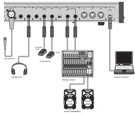
VOCODER VC340 Hook-up
Step 1: Hook-Up
Studio System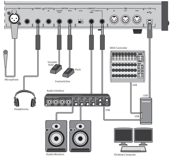
Band / Practice System
Live System
System with external Synthesizer
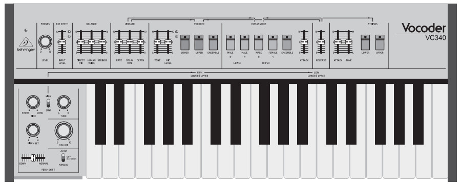
VOCODER VC340 Controls
 VOCODER VC340 Controls
TOP PANEL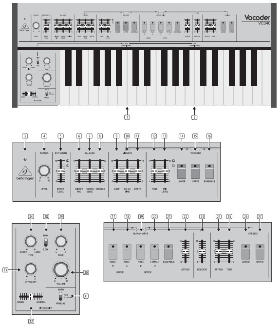 REAR PANEL

Step 2: Controls
KeyboardThe keyboard split is marked in two places, depending on the setting of the Low/High Octave switch.
- HIGH – this is the keyboard split position when the Octave switch is set to HIGH.
- LOW – this is the keyboard split position when the Octave switch is set to LOW.Upper Left Section
- POWER LED – this LED will turn on when the unit is connected to a live AC power supply and the rear panel power switch is on.
- PHONES LEVEL – adjust the overall volume level of the rear panel PHONES output. To reduce the possibility of hearing damage, turn this to minimum before putting on headphones or turning on the unit, and then bring up to a comfortable listening level.
- EXT SYNTH LEVEL – adjust the level of any audio coming into the rear panel external synthesizer input. A red LED shows when the input signal is too high.Balance SectionThese three faders allow you to balance the levels of the various sources.
- DIRECT MIC LEVEL – adjust the level of the direct microphone vocals, unaffected by the VOCODER.
- HUMAN VOICE LEVEL – adjust the HUMAN VOICE output level.
- STRINGS LEVEL – adjust the STRINGS output level.Vibrato SectionThe vibrato affects the VOCODER and HUMAN VOICE.
- RATE – adjust the frequency of the low-frequency oscillator modulating the VOCODER and HUMAN VOICE.
- DELAY TIME – adjust the delay time before the vibrato begins.
- DEPTH – adjust the depth or effect of the vibrato.Vocoder SectionThis section allows the keyboard to play the VOCODER, based on the audio input from your microphone. Adjust the microphone level using the MIC LEVEL fader, and adjust the TONE and MIC LEVEL faders carefully to prevent feedback in your speaker system. The direct microphone signal level can be added using the DIRECT MIC fader in the BALANCE section.
- TONE – adjusts the tone of the VOCODER section.
- MIC LEVEL – adjusts the level of the microphone signal entering the rear panel microphone input. A red LED shows when the incoming mic signal is too high.
- LOWER – select this to play the keys below the keyboard split.
- UPPER – select this to play the keys above the keyboard split.
- ENSEMBLE – this creates the effect of an extensive chorus to the VOCODER. (The UPPER and/or LOWER switches also have to be on, or there will be no output.)Human Voice SectionThis section allows the keyboard to play simulations of the human voice. The level is adjusted using the HUMAN VOICE fader in the BALANCE section. The 4’ or 8’ markings are based upon the traditional length designations of a drawbar organ (4’ is one octave higher than 8’).
- LOWER: MALE 8’ – select the lower section of the keyboard to play a simulation of the male voice.
- LOWER: MALE 4’ – select the lower section of the keyboard to play a simulation of the male voice.
- UPPER: MALE 8’ – select the upper section of the keyboard to play a simulation of the male voice.
- UPPER: FEMALE 4’ – select the upper section of the keyboard to play a simulation of the female voice.
- ENSEMBLE – this creates the effect of an extensive chorus to the HUMAN VOICE output. (The UPPER and/or LOWER switches also have to be on, or there will be no output.)
- ATTACK – adjusts the time it takes for the played a note in the HUMAN VOICE section to reach maximum volume. Position 0 gives no delay, so the sound will reach the maximum level immediately at the keypress.
- RELEASE – this fader affects the VOCODER, HUMAN VOICE, and STRINGS. It adjusts the time for the played note to decay from its maximum volume. Position 0 gives no delay, so the sound will turn of immediately following the key release.Strings SectionThis section allows the keyboard to play a simulation of strings. The level is adjusted using the STRINGS fader in the BALANCE section.
- ATTACK – adjusts the time it takes for the played note in the STRINGS section to reach its maximum volume.
- TONE – adjusts the tone of the STRINGS section.
- LOWER – select the lower section of the keyboard to play the STRINGS simulation.
- UPPER – select the upper section of the keyboard to play the STRINGS.Lower Left Controls
- HIGH/LOW – this affects the keyboard by moving it up (HIGH) or down (LOW) one octave.
- TUNE – adjusts the pitch up or down.
- VOLUME – Adjusts the volume level of the rear panel main outputs. It does not affect the headphone output. Turn this to a minimum before turning on the unit, and then bring it up to a comfortable listening level.Pitch Shift Section
- AUTO – when notes are played, they will automatically increase in pitch. Use the TIME and PITCH SET knobs to control the timing and range of the pitch shift.OFF – when notes are played, they will not automatically increase in pitch unless an external pedal is pressed.MANUAL – when notes are played, the pitch can be shifted manually using the DOWN/ NORMAL fader.
- DOWN/NORMAL – use this horizontal fader to manually shift the pitch when the adjacent switch is set to MANUAL. The pitch shift range is set by the PITCH SET knob.
- PITCH SET – adjusts the starting pitch of the pitch shift.H position: no pitch shift occurs.L position: maximum pitch shift occurs.
- TIME – adjusts the time it takes for the pitch shift to occur. It has no effect in MANUAL mode.Rear Panel
- POWER SWITCH – turn this switch on after all connections have been made. The power switch should be readily accessible during operation.
- AC INPUT – connect to an AC mains outlet capable of supplying 100 to 240 VAC, 50/60 Hz. Use only the supplied power cord.
- VENTILATION – these ventilation slots allow air low for cooling the internal circuits. Do not cover any of these slots.
- MICROPHONE XLR Input – connect to a microphone for use with the VOCODER. Microphones that require phantom power should not be used. Use only one microphone input at a time.
- MICROPHONE TRS Input – connect to a microphone for use with the VOCODER.
- PHONES OUTPUT – connect to a pair of stereo headphones. Make sure the top panel PHONES level knob (4) is turned down before putting on headphones, and then bring up to a safe listening level.
- EXTERNAL SYNTH INPUT – this input allows connection of the line-level audio output from an external device such as a synthesizer. The input level is adjusted using the top panel EXT SYNTH (5) input level fader.
- VOCODER HOLD – connect a standard footswitch here so you can easily engage or disengage the VOCODER.
- PITCH SHIFT – connect a standard footswitch here so you can turn on or of the pitch shift effect. Make sure the pitch shift switch (31) is set to OFF (EXT CONTROL).
- L/M/H SWITCH – adjusts the output level from Low, Medium, or High, to best match your system. For example, Low can be used when connecting to a mixer channel input, High used for a line-level input, and Medium used if a lower level is better.
- MONO OUTPUT – this output is used to connect to a single amplifier, powered speaker, or mixer channel for example. The two internal channels of the VOCODER VC340 are summed together.
- STEREO OUTPUT – if you want to connect the VOCODER VC340 to a stereo system, such as a 2-channel amplifier, 2 powered speakers, or 2 mixer channels, then use this output and the Mono Output.MIDI Section
- MIDI IN – this 5-pin DIN jack receives MIDI data from an external source such as a MIDI keyboard, an external hardware sequencer, a computer equipped with a MIDI interface, etc.
- MIDI THRU – this is used to pass through MIDI data received at the MIDI INPUT.
- MIDI OUT – this 5-pin DIN jack sends MIDI data generated by the VOCODER VC340 to other MIDI devices such as an external synthesizer or a computer equipped with a MIDI interface, etc.
- USB PORT – This USB type B jack allows connection to a computer. The VOCODER VC340 will show up as a class-compliant USB MIDI device, capable of supporting MIDI in and out.USB MIDI IN – accepts incoming MIDI data from an application.USB MIDI OUT – sends MIDI data to an application.
VOCODER VC340 Getting started
OVERVIEWThis “getting started” guide will help you set up the VOCODER VC340 analog synthesizer and briefly introduce its capabilities.CONNECTIONTo connect the VOCODER VC340 to your system, please consult the hook-up guide earlier in this documentSOFTWARE SETUPThe VOCODER VC340 is a USB Class Compliant MIDI device, and so no driver installation is required, and it does not require any additional drivers to work with Windows and macOS.HARDWARE SETUP
- Make all the connections in your system.
- Apply power to the VOCODER VC340 using the supplied IEC power cord only.
- Make sure the main volume knob is turned down and that your amplifiers or powered speakers are turned off.
- Turn on the rear panel power switch, and then turn on the rest of your system.
UPPER/LOWERThe keyboard split has two positions marked HIGH and LOW on the top panel, and this depends upon the setting of the HIGH/LOW octave switch. Any UPPER switches ON will allow the keys above the split to play. Any LOWER switches ON will allow the keys below to play.
INITIAL SETUP (STRINGS)The following example using STRINGS will get you started:
- Turn on the UPPER and LOWER STRINGS switches.
- Turn up the STRINGS fader in the BALANCE section.
- Play the keyboard and adjust the VOLUME and the settings of your external equipment to a safe listening level.
- Adjust the ATTACK fader to vary the amount of time taken for the maximum level to be reached after a keypress.
- Adjust the RELEASE fader to vary the amount of time taken for the sound level to decay once a key is released. This fader also affects the HUMAN VOICE and VOCODER.
- Adjust the TONE fader. ADDING HUMAN VOICE
- Turn on some of the HUMAN VOICE switches.
- Adjust the HUMAN VOICE fader in the BALANCE section as you play. Readjust the STRINGS fader to balance or turn it down/off as desired.
- Experiment with the other switches such as ENSEMBLE.
- Adjust the HUMAN VOICE ATTACK fader as desired.
- Adjust the RELEASE fader as mentioned in the STRINGS section above.
- Adjust the three VIBRATO faders to add modulation to the HUMAN VOICE if desired. These faders also affect the VOCODER.ADDING DIRECT MICROPHONE
- Turn on your microphone and sing along or talk. This is the direct vocals, with no added VOCODER.
- Adjust the MIC LEVEL fader in the VOCODER section, making sure that the level is not high enough for the adjacent red LED to come on.
- Adjust the DIRECT MIC fader in the BALANCE section, and adjust the STRINGS and HUMAN VOICE fader as desired.USING THE VOCODER
- Turn on the UPPER and LOWER VOCODER switches.
- Turn on your microphone and sing along or talk.
- Turn down the DIRECT MIC fader, and the STRINGS and HUMAN VOICE faders.
- Adjust the MIC LEVEL fader in the VOCODER section, making sure that the level is not high enough for the adjacent red LED to come on.
- As you play the keyboard and sing/talk, you will hear the VOCODER output. (There will be no output if you are not singing or talking while playing, or if the MIC LEVEL is down.
- Try using the ENSEMBLE.
- Adjust the VOCODER TONE fader, and re-adjust the MIC LEVEL as desired, to prevent feedback from your speakers.
- Adjust the three VIBRATO faders to add modulation to the VOCODER if desired. These faders also affect the HUMAN VOICE.
- Add in the STRINGS and HUMAN VOICE by adjusting their faders in the BALANCE section.VOCODER HOLD PEDALA footswitch connected to the rear panel VOCODER HOLD input, will allow you to engage/disengage the VOCODER:
- As you sing and play, press and hold the footswitch at any time to hear your VOCODER vocals.
- Release the footswitch to turn off the vocal
USING THE VOCODER WITH AN EXTERNAL SYNTHYour vocals can be affected by the incoming audio from an external synthesizer and not by the internaVOCODER circuitry. The VOCODER UPPER/LOWER switches have no effect.
- Connect the line-level audio output from an external synthesizer to the rear panel EXT SYNTH input.
- Play the synthesizer and adjust the EXT SYNTH INPUT LEVEL fader so the red LED neto this fader does not come on.
- Sing/talk and adjust the MIC LEVEL fader in the VOCODER section, so the red LED next to this fader does not come on.
- As you play the keyboard and sing/talk, you will hear the vocals affected by the synthesizer audio.
PITCH SHIFTThe pitch of the played notes can be shifted automatically, manually, or selected using a pedal connected to the rear panel pitch control connections the AUTO/OFF/MANUAL switch and the other nearby controls to select how to PITCH SHIFT works:AUTOMATICNotes and vocals will automatically increase in pitch.Use the PITCH SET knob to adjust the pitch. In automatic mode, the pitch increases to the maximum, which is if this knob was at H. So, if the knob is already on H, then no pitch shift occurs. If it’s on L, then a maximum pitch shift occurs.Use the TIME knob to adjust the time it takes for the pitch shift to occur.OFF/EXT CONTROLIn this position, there will be no pitch shift unless you are using an optional external footswitch connected to the rear panel PITCH SHIFT connector the footswitch is held down, then the pitch shift will occur, with settings and controls just like the AUTOMATIC position described above. Release the footswitch to stop pitch shift from occurring.MANUALUse the DOWN/NORMAL fader to easily shift the pitch while you play.Use the PITCH SHIFT knob to set the fader’s pitch range. For example Knob on H – fader movement has no effect. The knob on L – fader will allow maximum pitch shift. (The TIME knob has no effect in MANUAL mode).FIRMWARE UPDATEPlease check our website behringer.com regularly for any updates to the firmware of your VOCODER VC340 synthesizer. The firmware file can be downloaded and stored on your computer, and then used to update the VOCODER VC340. It comes with detailed instructions on the update procedure.HAVE FUNMake copies of the patch sheet at the end of this manual, and record your favorite settings.With all these controls, the possibilities for musical creativity are endless. We hope that you will enjoy your new VOCODER VC340.
VOCODER VC340 Special Modes
VELOCITYThe keyboard velocity can be set to a fixed value or a value that varies dynamically with how hard the keys are struck. The following procedure shows how to change the velocity:
- Turn off the Power.
- Hold down both ENSEMBLE switches while turning on the power.
- If all the LEDs blink fast, then the current velocity is a fixed value (127). The loudness of the notes will not change if the keys arepressed soft or hard.
- If all the LEDs blink slowly, then the current velocity will vary dynamically. The loudness of the notes will vary if the keys are pressedsoft or hard.
- Release the two ENSEMBLE switches and the VC340 will save the current setting.
- To change to the other setting, repeat steps 1 and 2.
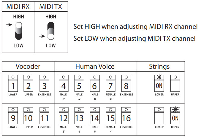
MIDI ChannelThe MIDI transmit and receive channel numbers can be selected from 1 to 16, using the following procedure:
- Turn off the Power.
- Hold down both the STRINGS section UPPER and LOWER switches, while turning on the power.
- All LEDs should flash 3 times fast, showing that the VC340 is in its MIDI channel setting mode.
- Release the STRINGS switches.
- To first set the MIDI RX channel, set the OCTAVE switch to HIGH.
- The 8 VOCODER and HUMAN VOICE switches are used to select the channel numbers as follows:
- If the STRINGS LOWER switch is selected, the 8 switches represent channel numbers 1 to 8.
- If the STRINGS UPPER switch is selected, the 8 switches represent channel numbers 9 to 16.
- Select the required channel number.
- To set the MIDI RX channel to ALL, press and hold both ENSEMBLE switches. (This is only available in RX, so the VC340 can receive incoming MIDI from all channels.)
- To select the MIDI TX channel, first set the OCTAVE switch to LOW, and repeat steps 6 to 9 above.
- To exit, press both the STRINGS UPPER and LOWER switches at the same time. The channel numbers will be saved, and theVC340returned to normal operation.ExamplesTo set MIDI RX to channel 3:
- OCTAVE switch HIGH
- STRINGS LOWER ON
- VOCODER ENSEMBLE switch ON
- Press STRINGS UPPER and LOWER at the same time to exitTo set MIDI TX to channel 10:
- OCTAVE switch LOW
- STRINGS UPPER ON
- VOCODER UPPER switch ON
- Press STRINGS UPPER and LOWER at the same time to exitTo set MIDI RX to ALL:
- OCTAVE switch HIGH
- Press both ENSEMBLE switches at the same time. All 8 LEDs will be on.
- Press STRINGS UPPER and LOWER at the same time to exit
MIDI Channel number selection
VOCODER VC340 SysEx information
SYSTEM EXCLUSIVE COMMANDSSome parameters can be changed using MIDI system exclusive (SysEx) commands. A MIDI utility such as MIDI-OX can be used to send a SysEx command data string from the computer to the VOCODER VC340 using the USB MIDI connection. You can send these commands manually or use the Behringer SynthTool App which is a free download from our website.
SysEx Data Format
| F0 | Manu ID | Model ID | D1 | … | Dn | F7 |
Manu ID: 00 20 32, Behringer GmbHModel ID: 00 01 07, Behringer Vocoder VC340DO-Dn: Data for configuration, the range is 00-7F.
MIDI Channel
| F0 | Manu ID | Model ID | 0E | 01 | Data1 | Data 2 | F7 |
| Data | Description | Range | Default |
| Data1 | MIDI TX channel | 00 to 0F | 00-Channel 1 |
| Data2 | MIDI RX channel | 00 to 0F: channels 1 to 1610: all channels | 00-Channel 1 |
| FO | Model ID | Model ID | OF | Data1 | F7 |
| Data | Description | Range | Default |
| Data1 | Note transpose | 00 to 18 (The transposethe range is -12 to +12) | 0C-No transpose |
Example: Set note transpose to +8: F0 00 20 32 00 01 07 0F 14 F7
Velocity
| FO | Manu ID | Model ID | 10 | Data1 | Data2 | Data 3 | F7 |
| Data | Description | Range | Default |
| Data1 | Note on velocity | 00: dynamic velocity01-7F: is a fixed value of velocity | 00 |
| Data2 | Note off velocity | 00: dynamic velocity01-7F: is a fixed value of velocity | 00 |
| Data3 | Velocity curve | 00-soft, 01-med, 02-hard | 01-med |
Example: Set note on velocity to dynamic, note-off velocity to fixed value 64, and set the curve to hard: FO 00 20 32 00 01 07 10 00 64 02 F7.
Output Level Control
If the output level is controlled by velocity enable, the loudness of each note can be affected by velocity, or it will work with maximum loudness.
| FO | Manu ID | Model ID | 18 | Data1 | F7 |
| Data | Description | Range | Default |
| Data1 | Set loudness enable or disable | 00-disable 01-enable | 00-disable |
Example: Set output level controlled by velocity enable: F0 00 20 32 00 01 07 18 01 F7.Restore Factory Setting
| FO | Manu ID | Model ID | 7D | F7 |
Specifications
| Synthesizer Architecture | |
| Implementation | Analog |
| Keyboard | |
| Keys | 37 semi-weighted, full-size keys |
| Keyboard sensing | Note on/of velocity |
| Upper Left Section | |
| Faders | External synthesizer input level |
| Rotary knobs | Headphones level |
| LED | Power, external signal present, clip (red) |
| Lower Left Section | |
| Faders | Pitch shift: down-normal |
| Rotary knobs | Volume, tune, pitch set, pitch time |
| Switches | Keyboard split selection: low/high, pitch shift:auto/of (external control)/manual |
| Balance Section | |
| Faders | Direct mic level, human voice level, strings level |
| Vibrato Selection | |
| Faders | Rate, delay time, depth |
| Vocoder Section | |
| Faders | Tone, mic input level |
| Switchers | Lower, upper, ensemble |
| LEDs | Mic signal present, mic clip (red),lower, upper, ensemble |
| Human Voice Section | |
| Faders | Attack |
| Switchers | male 8’ lower, male 4’ lower, male 8’ upper,female 4’ upper, ensemble |
| LEDs | male 8’ lower, male 4’ lower, male 8’ upper,female 4’ upper, ensemble |
| Release Section | |
| Fader | Release (for strings, human voice, vocoder) |
| Digital Effects | |
| Faders | Attack, tone |
| Switchers | Lower, upper |
| LEDs | Lower, upper |
| Rear Panel | |
| Switches | Power on/of, output level: low/medium/high |
| Connectivity | |
| MIDI In/Out/Thru | 5-pin DIN / 16 channels |
| USB | USB 2.0, type B |
| Pitch control | 1/4″ TS |
| Vocoder hold | 1/4″ TS |
| External synth input | 1/4″ TS, unbalanced, max. +12 dBu |
| Output L/R | 1/4″ TS, stereo or mono, unbalanced,max. +14 dBu (high), +0 dBu (mid), -13 dBu (low) |
| Headphones | 1/4″ TRS, unbalanced, max. +12 dBu @32-ohm load |
| Microphone input | 1/4″ TRS, and XLR female, max. -3 dBu |
| USB | |
| Type | Class-compliant USB 2.0, type B |
| Supportedoperating systems | Windows 7 or higherMac OS X 10.6.8 or higher |
| Power Requirements | |
| Mains connector | Standard IEC receptacle |
| Power consumption 1 | 5 W max. |
| Internal Switch-mode PSU | Auto range 100-240 V, (50/60 Hz) |
| Environmental | |
| Operatingtemperature range | 5°C – 40°C (41°F – 104°F) |
| Physical | |
| Dimensions (H x W x D) | 103 x 649 x 257 mm (4.1 x 25.6 x 10.1″) |
| Weight | 6.6 kg (14.5 lbs) |
| Shipping Weight | 8.4 kg (18.5 lbs) |

Important information
- Register online. Please register your new Music Tribe equipment right after you purchase it by visiting musictribe.com. Registering your purchase using our simple online form helps us to process your repair claims more quickly and efficiently. Also, read the terms and conditions of our warranty, if applicable.
- Malfunction. Should your Music Tribe Authorized Reseller not be located in your vicinity, you may contact the Music Tribe Authorized Fulfiller for your country listed under “Support” at musictribe.com. Should your country not be listed, please check if your problem can be dealt with by our “Online Support” which may also be found under “Support” at musictribe.com. Alternatively, please submit an online warranty claim at musictribe.com BEFORE returning the product.
- Power Connections. Before plugging the unit into a power socket, please make sure you are using the correct mains voltage for your particular model. Faulty fuses must be replaced with fuses of the same type and rating without exception.
FEDERAL COMMUNICATIONS COMMISSION COMPLIANCE INFORMATION
BEHRINGER
VOCODER VC340
Responsible Party Name: Music Tribe Commercial NV Inc.Address: 5270 Procyon Street,Las Vegas NV 89118,United StatesPhone Number: +1 702 800 8290
VOCODER VC340This equipment has been tested and found to comply with the limits for a Class B digital device, pursuant to part 15 of the FCC Rules. These limits are designed to provide reasonable protection against harmful interference in a residential installation. This equipment generates, uses and can radiate radio frequency energy and, if not installed and used in accordance with the instructions, may cause harmful interference to radio communications. However, there is no guarantee that interference will not occur in a particular installation. If this equipment does cause harmful interference to radio or television reception, which can be determined by turning the equipment off and on, the user is encouraged to try to correct the interference by one or more of the following measures:
- Reorient or relocate the receiving antenna.
- Increase the separation between the equipment and receiver.
- Connect the equipment into an outlet on a circuit different from that to which the receiver is connected.
- Consult the dealer or an experienced radio/TV technician for help.This device complies with Part 15 of the FCC rules. Operation is subject to the following two conditions:(1) this device may not cause harmful interference, and(2) this device must accept any interference received, including interference that may cause undesired operation.Important information:Changes or modifications to the equipment not expressly approved by Music Tribe can void the user’s authority to use the equipment.
 Hereby, Music Tribe declares that this product is in compliance with Directive 2014/35/EU, Directive 2014/30/EU, Directive 2011/65/EU, and Amendment 2015/863/EU, Directive 2012/19/EU, Regulation 519/2012 REACH SVHC and Directive 1907/2006/EC.Full text of EU DoC is available at https://community.musictribe.com/EU Representative: Music Tribe Brands DK A/SAddress: Ib Spang Olsens Gade 17, DK – 8200 Aarhus N, Denmark
We Hear You
![]()
References
[xyz-ips snippet=”download-snippet”]