BeingHD Touch Manager Modular Matrix Switcher

SAFETY
To protect the device and operating personnel from electrostatic discharge, you need to check and ensure that the device is grounding well before the device is powered on. Please observe the following when you install, use, maintain this equipment.Attention the equipment needs good earth grounded
- Please use single-phase three wire system AC 220V power supply, and ensure all transmission system is grounding well.
- To protect operating personnel and the device please turn off all power supplies and pull the plug before moving the device or doing some specific works which need to be done when the electricity is turned off . Please turn off the main power switch on rainy days or when not in use for a long time.
- Please do not put anything upon the cables, or tread the cables.
- To avoid damaging the device, please turn off power supply before plugging cable into the device or pulling cable from device. The damage caused by plugging/ pulling cables without turning off power supply is outside the scope of the warranty.
- The power of the device gives out heat when it works, so it’s necessary to keep the work environment ventilated to protect the device from the damage caused by over temperature.
- Do not place the device in very cold or very hot places. Do not sprinkle any corrosive chemicals or liquid on or around the device.
- ➢ To avoid accident or any further damage ,non-professionals please do not dismantle or maintain the device without permission.
Product Introduction
The TOUCH MANAGER modular matrix switcher series include two:TOUCH-MANAGER-800(80×80) and TOUCH-MANAGER-1600(160×160). All the signal input and output cards using 1-card 4-port, wide range selections of the input and output cards, it provides users the most flexible configuration ability to meet with the real applications. And the 1080P and 4K60 I/O cards can reach any switching, converting, extension, resolution adjustment. Supports seamless or fast switching function, electromagnetic protection function, it can efficiently shield the electromagnetic interference for the surrounding environment to make sure the equipment running more stable.
The single channel signal switching speed can reach 12.5Gbps, and the main board is using Four core four links processing technology, the switching ability speed can reach 32Gbps. With uncompressed transmission technology for the digital signal to make sure the image High fidelity output. Unique signal links shielding designing technology to make sure the signal completeness, the internal data switch has super strong capacity of resisting disturbance and long continuous and stable working ability. Supports 7*24 continuously working and with dual LAN and RS232 backup control, it’s convenient for users to control via PC, iPad, APP and the 3rd parties central control by the the RS232 control commands.
With the dual RS232 and LAN control, users also can simply set up and control the surrounding equipment, such as the projector, electric curtain and TVs.This matrix switchers have been widely used in the conferencing, radio & television project, multimedia conferencing hall, large screen display project, television teaching, command control center and so on applications.
Product Features
- Modular designing chassis
- 4-channel 1 card, supports DVI-I/ HDMI/ 3GSDI/ HDBaseT/ Fiber to mix input and output
- Support seamless switching between all the signals
- 4-core 4 links processing chipset provides up t0 32GBPS signal switching processing ability
- Front buttons with background lights, easier to operate at any time
- Support EDID automatic recognition and compatible with HDCP
- Support 3.5mm audio embedded and de-embedd function
- Support 4K60, HDMI2.0 444 digital HD video signal transmission and seamless switching
- Support 3D image frequency repairing, pixel reread processing function
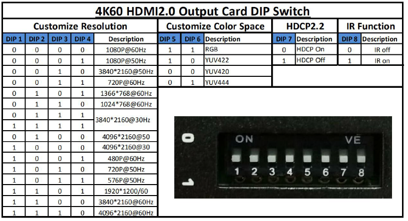
- Support scaling up/down function via the DIP switch
- Support dual LAN ports backup control and centralization network management function
- Support hot-plug function
- Support auto saving protection and auto recovery function while power cut
Technical Datasheet
| Model | TOUCH-MANAGER-800 |
| Description | 80×80 Modular Matrix Switch |
| Input card | 1 card 4- port, Support HDMI/ DVI/ 3GSDI/ HDBaseT/ Fiber |
| Output card | 1 card 4-port, Support HDMI/ DVI/ 3GSDI/ HDBaseT/ Fiber |
| Protocol | HDMI1.4a/ HDMI2.0, DVI1.0, compatible with HDCP and EDID function |
| Color Space | RGB444, YUV444, YUV422, support x.v. Color extension color gamut standard |
| Resolution | 640×480—1920×(VESA), 480i—4K30Hz(HDTV), 4K60Hz |
| Bandwidth | 12.5Gbps |
| Transmission Distance | 70/100m(Cat6), 80Km(Single-mode), 20m(Digital cable), 25m(Analog cable) |
| Control | Dual RS232, dual LAN(WEB GUI), front touch panel, iPad APP |
| Dimension | 482*390*711mm(16U) |
| Weight | 28KG(No cards) |
| Power | 110–260V 50/60Hz |
| Consumption | 180W(No cards) |
| Working Temperature | -10℃-50℃ |
| Storage Temperature | -20℃-55℃ |
| Working Humidity | 10%-90% |
Packing Details
Matrix switch chassis with customized
configuration …. 1 unit
Power cord pcs …… ..2
User manual pcs ……. 1
Panels(Here take example with 10×10)
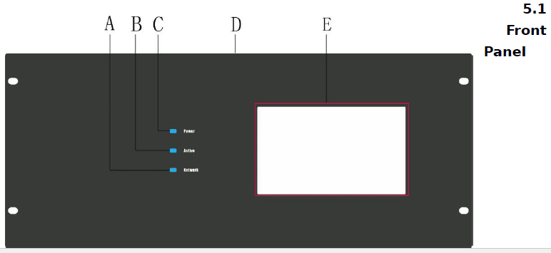
A: Network Indicator: Shows the operations of WEB control, flicking once for every operationsB: Active Indicator: Shows the operations of Touch panel control, flicking once for every operationsC: Power Indicator: Light up means power on, flicking means connection problemD: Front Panel: 482*711mmE: 10 inch touch screen
Back Panel

A: Back rack earB: 3.5mm Audio inputC: Status indicator: Power on will light upD: DVI-I interface input, support DVI/ HDMI/ CVBS/ Ypbpr/ VGA input with adaptersE: Input area, maximum can support 80/ 160inputs, signals can be DVI/ HDMI/ CVBS/ Ypbpr/ VGA/ Fiber OpticF: Plug helperG: Input and output indicates flap, left side is 1-80 inputs, right side is 1-80outputsH: 3.5mm Audio outputJ: DVI-I interface output, support DVI/ HDMI/ CVBS/ Ypbpr/ VGA input with adaptersK: Output area, maximum can support 80/ 160 inputs, signals can be DVI/ HDMI/ CVBS/ Ypbpr/ VGA/ Fiber OpticL & N: Dual RS232 portsM & O: Dual LAN portsP: ON/ OFF power switcherQ: Redundant power system, 100-240V 50/60Hz
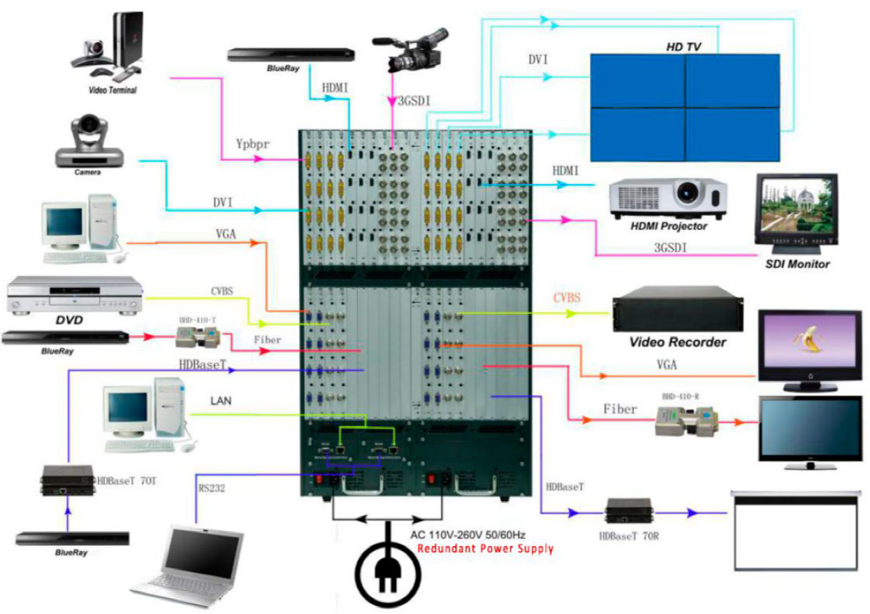
Connection Diagram
Operation
Touch Screen
After power on, it shows below interface: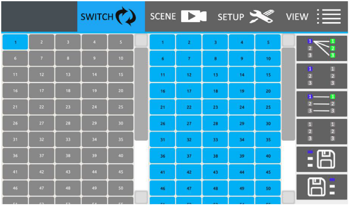
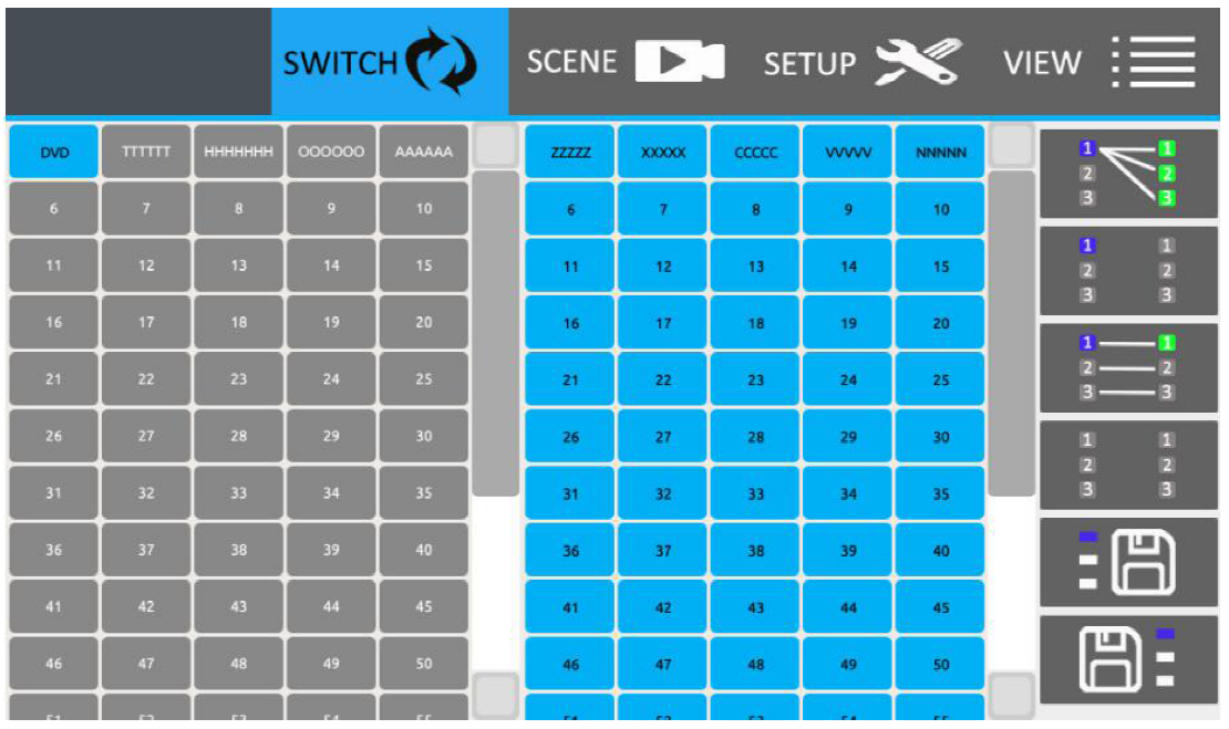
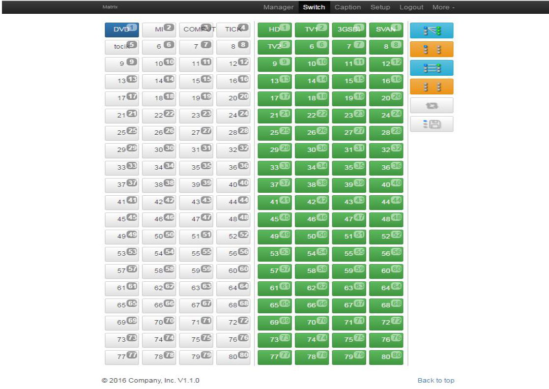
Switch Icon:After click switch icon, it shows below interface: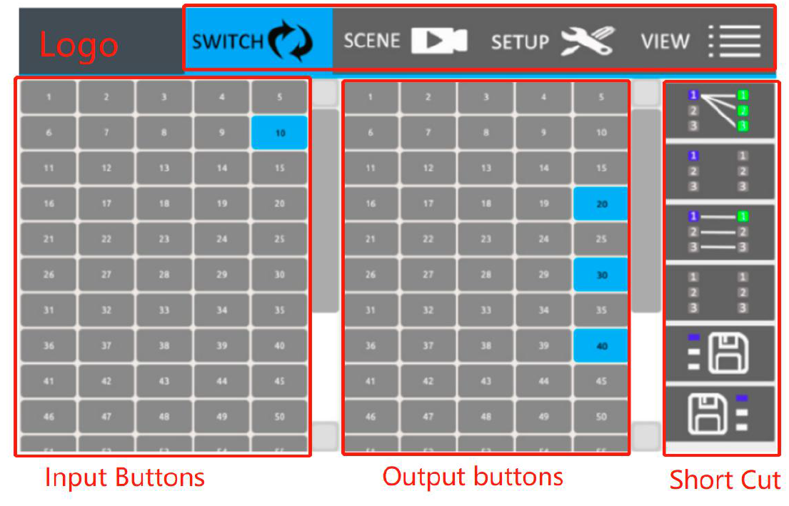
Eg. Switch input 10 to output 20/30/40.Press number 10 from input buttons, and color turns to blue. Then same way to press number 20/30/40 on the output buttons area, shows as above picture.
SCENE Icon:Total can save 24 scenes, after press SCENCE it will show below interface:
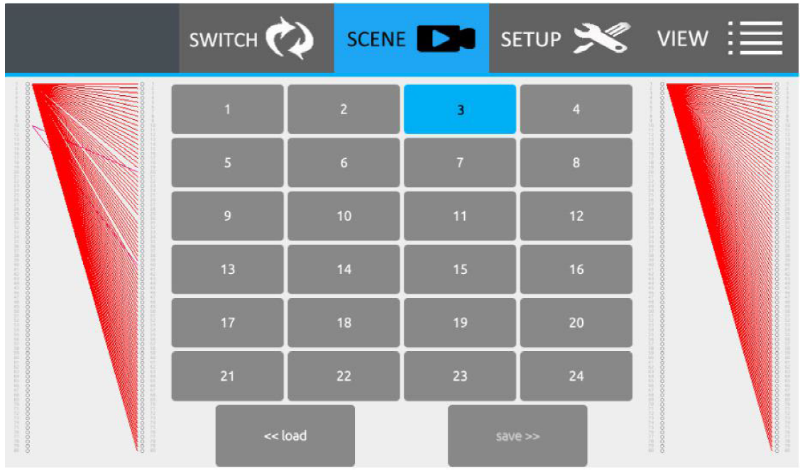
Save scene: After pressed scene icon, users can see above interface. Then users can choose any number buttons from the above 24, and then press Save. Such as, users want to save the current switching status to scene 1, users only need to press number 1 and then choose Save.(Note: This function only can be used under unlock status)
Recall scene: After the scenes saved successfully, user also can choose the scene name to recall the previous/saved switching status. Such as users want to recall scene 6, only need to press number 6 and then press load. Users also can preview the scene switching status by both side windows next to the numbers.
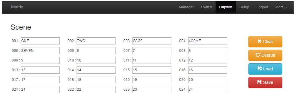
SETUP Icon:Users can change the name of Scene, input and output here. After changing the default settings, users need to press Save to save the changes.Change the name of scenes, only need to press Scene icon at the left bottom, showing as below
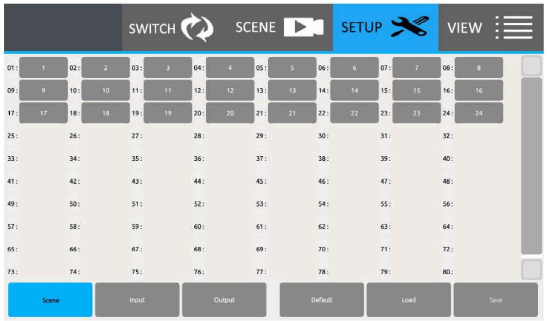
Then change to the needed names:

Then change to the needed names:Users also can change all the 24 scenes name together or one by one and then to press the save button, as below
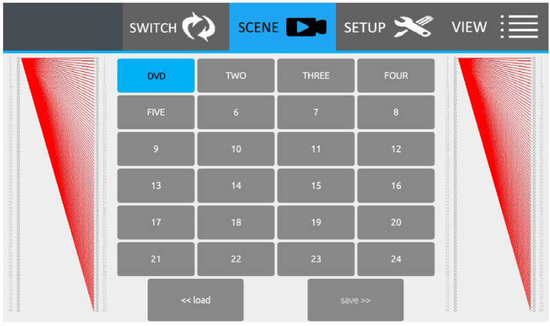 Change the name of Input and output, press the Input or Output icons, showing as below:After users changed the names, and when back to the SWITCH and SCENE interface, users can see the names have been well changed, showing as below:
VIEW Icon:After press VIEW button, will show below interface, users can change the IP maddress, display and sound settings here, also unlock and lock, get help information as so on.
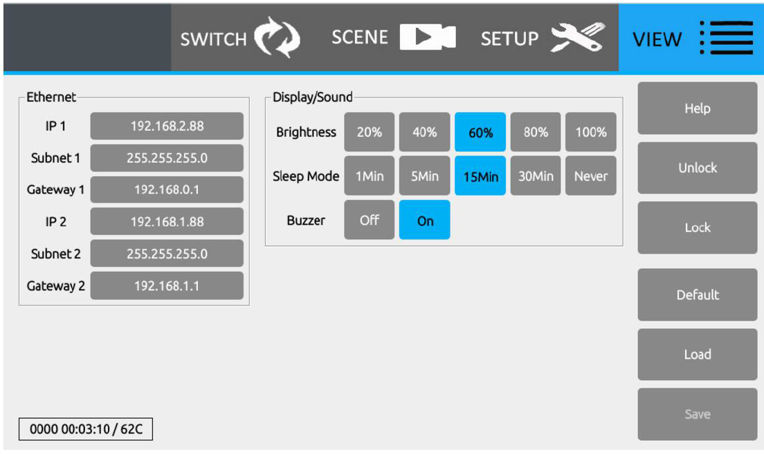
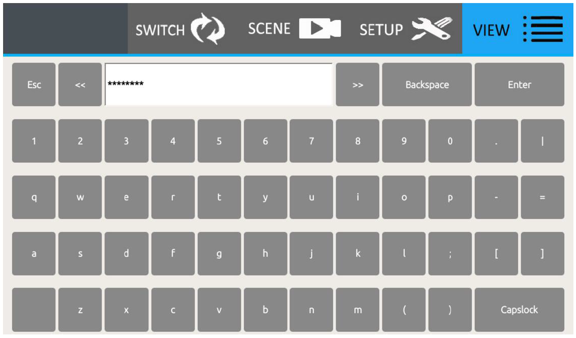
Unlock:All the equipment have been locked, users need to unlock the equipment if need to change the default settings.First, press Unlock button, and enter the default password: 12345678 and press Enter to unlock the equipment. After unlocked the equipment, users can change the names of the scene, inputs, outputs, IP address and so on.
Introduction for the shortcut icons:
| Introduction | Example | |
| Switch one to all | Press the input number, then press this button to switch to all | |
| Close the specific input switching status | Press any input number, then press this button to close the switching status | |
| Switch one to one | Press this button to realize one to one switching status | |
| Close all the switching status | Press this button to close all the switching status | |
| Save scene | Press this button will turn to the scene save interface | |
|
|
Recall scene | Press this button will turn to the scene recall interface |
WEB control
Touch Manager series products support dual control system, the default IP address are: 192.168.0.80(first one/ left one) and 192.168.1.80(first one/ right one). If users using the first one to control the matrix.First step, users need to make the sure RI-45 cable is workable and well connected with the control PC.Second, users need to change the IP address of the control PC at the same segment.Third, users only need to open the browser and type the matrix IP 192.168.0.80 and enter, will show below interface:
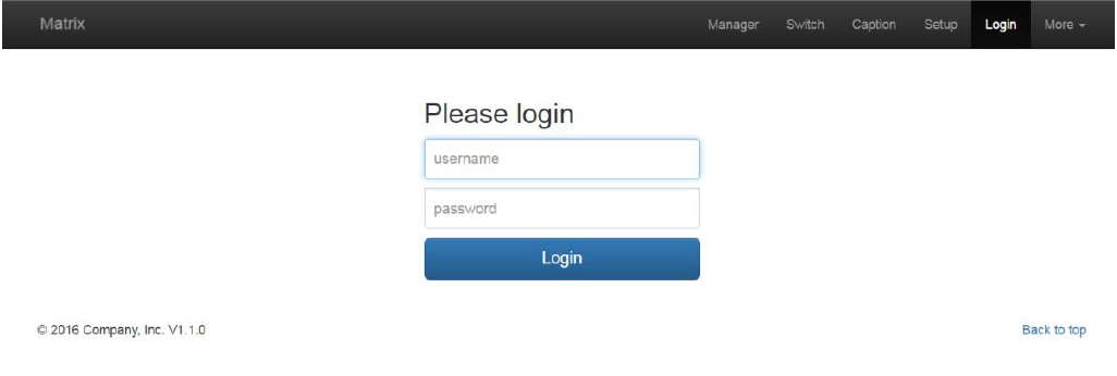
Default user name and password are the same: admin, then click to Logo in
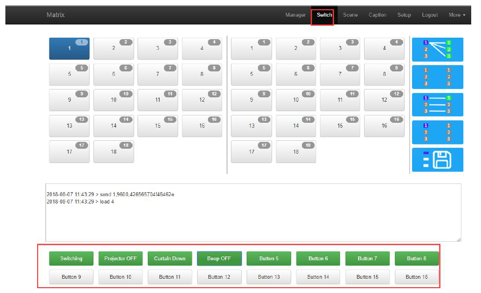
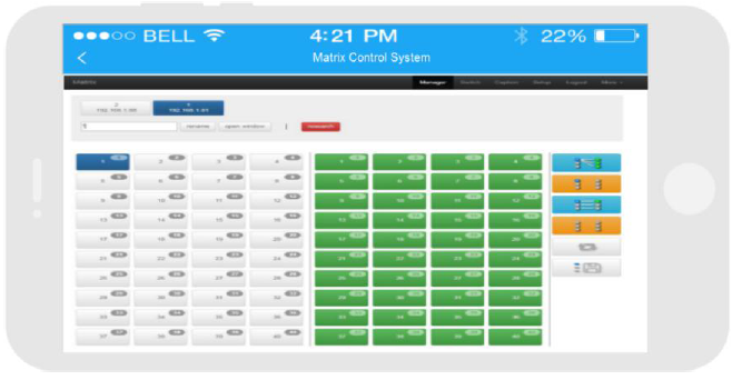
Switch interface:Users can switch and control with the same way on the touch panels
Caption Interface:Users can change the name of scene, inputs and outputs here, and click to save after changes
INPUT:
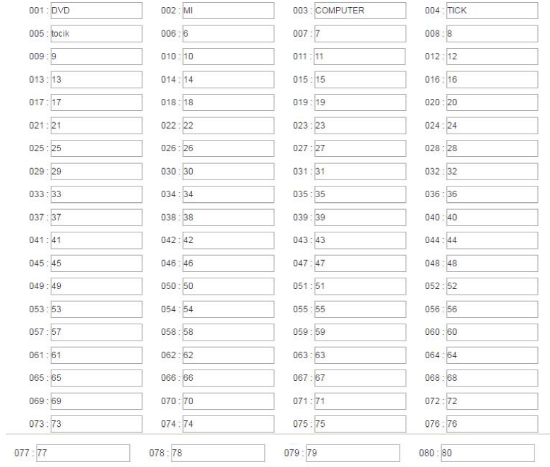
OUTPUT:

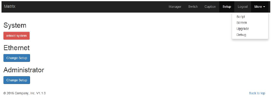
Setup
Set up interface:System Reboot: for modifying the matrix configuration(IP address, Login password)Ethernet: for changing IP address accordinglyAdministrator: For changing the Login user name and passwordMultifunction Buttons: For controlling the surrounding equipment

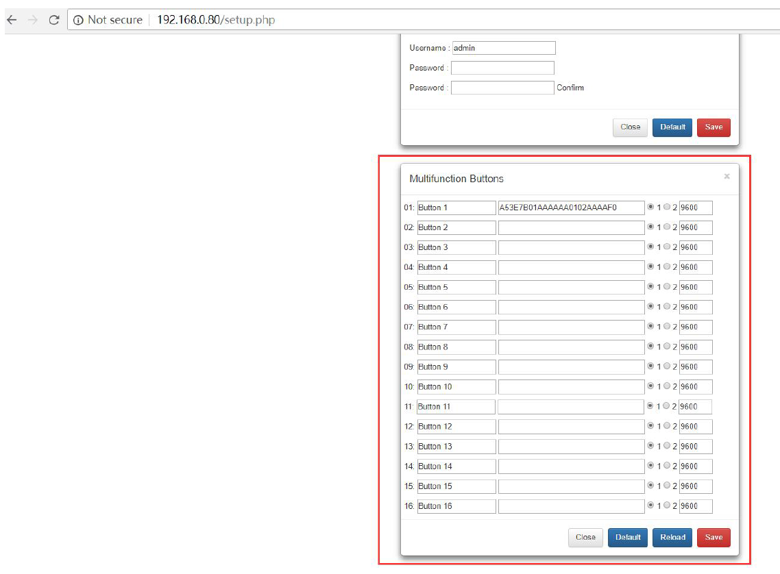
Multifunction buttons set up, total we have 16 multifunction buttons at present. We can rename the buttons, Type the HEX code for each button, and baud rate select. Then click “Save”.

More:Upgrading: Click Upgrade can realize new software upgrading
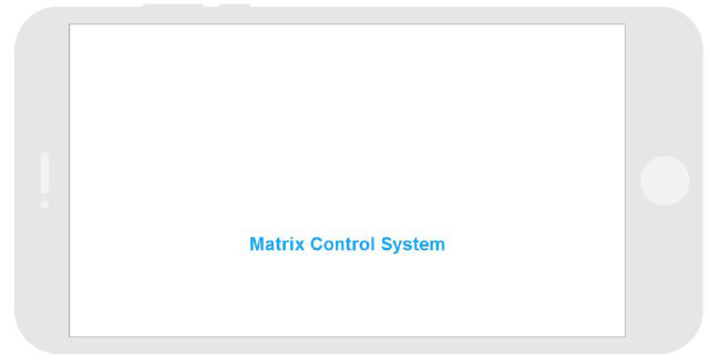
APP Control
It also can support IOS and Android APP control, users only need to well connected the matrix with the WIFI router or local network. Download the APP from the application store. The steps and interfaces show as below:Step 1: Make sure the matrix well connected with the router or local network, and open the APP:
Step 2: Enter the IP address of the matrix:
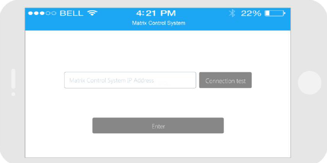
Step 3: After log in successfully, users can switch, change the inputs and outputs name directly.
Central Control Commands
RS232 cable with straight-through connection(USB-RS232 can be used directly to control)Communication protocol:Baud rate: 115200Data bit: 8Stop bit: 1Check bit: None
| Comman
ds |
Explanation | Function description |
|
YAll. |
Y=1,2,3,4…… |
Switch Input Y to all the outputs
Eg. “1ALL.” means switch input 1 to all outputs |
|
All1. |
One to one |
Switch all the channels to be one to one.Eg.1->1,2->2,3->3…… |
|
YXZ. |
Y=1,2,3,4……
Z=1,2,3,4…… |
Switch Input Y to Output Z
Eg. “1X2.” means switch Input 1 to output 2 |
|
YXZ&Q& W. |
Y=1,2,3,4……
Z=1,2,3,4…… Q=1,2,3,4…… W=1,2,3,4…… |
Switch Input Y to Output Z, Q, W
Eg. “1X2&3&4.” means switch Input 1 to Output 2, 3, 4 |
| SaveY. | Y=1,2,3,4…… | Save current status to scene Y
Eg. “Save2.” means saving current status to Scene 2 |
|
RecallY. |
Y=1,2,3,4…… |
Recall the saved scene Y
Eg. “Recall2.” means recall the saved Scene 2 |
| BeepON. | Beep sound | Buzzer on |
| BeepOFF. | Buzzer off | |
| Y?. | Y=1,2,3,4……. | Check the Input Y to outputs switching status
Eg. “1?.” means to check Input 1 switching |
Note:
- Every command ends with a period “.” and it can’t be missing.
- The letter can be capital or small letter.
- Switch success will return as “OK”, and failed will return as “ERR”.
Trouble Shooting and Attention
No signal on the display?
- Make sure all the power code well connected
- Check the display switcher and make sure it’s in good condition
- Make sure the the DVI cable between the device and display are short than 7 meters
- Reconnect the DVI cable and restart the system
- Make sure the signal sources are on
- Check the cables between the devices and displays are connected correctly.
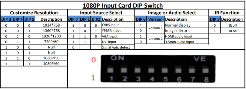
- Dial the switcher 7 to 1, then dial the switcher1,2 and choose the corresponding inputs.
- Make sure the resolution less than WUXGA(1920*1200)/ 60HZ
- Make sure the display can support the output resolution.
After Sales
Warranty Information
The Company warrants that the process and materials of the product are not defective under normal use and service for 2 (2) year following the date of purchase from the Company or its authorized distributors.If the product does not work within the guaranteed warranty period, the company will choose and pay for the repair of the defective product or component, the delivery of the equivalent product or component to the user for replacement of the defective item, or refund the payment which users have made.
The replaced product will become the property of the Company.The replacement product could be new or repaired.Whichever is longer, any replacement or repaired of the product or component is for a period of ninety (90) days or the remaining period of the initial warranty. The Company shall not be responsible for any software, firmware, information, or memory data contained in, stored in, or integrated with the product repaired by the customer’s return, whether or not during the warranty period.
Warranty limitations and exceptions
Except above limited warranty, if the product is damaged by over usage, incorrectly use, ignore, accident, unusual physical pressure or voltage, unauthorized modification, alteration or services rendered by someone other than the Company or its authorized agent, the company will not have to bear additional obligations. Except using the product properly in the proper application or normal usage
Attachment A:Input and output cards for TOUCH-MANAGER-800/1600
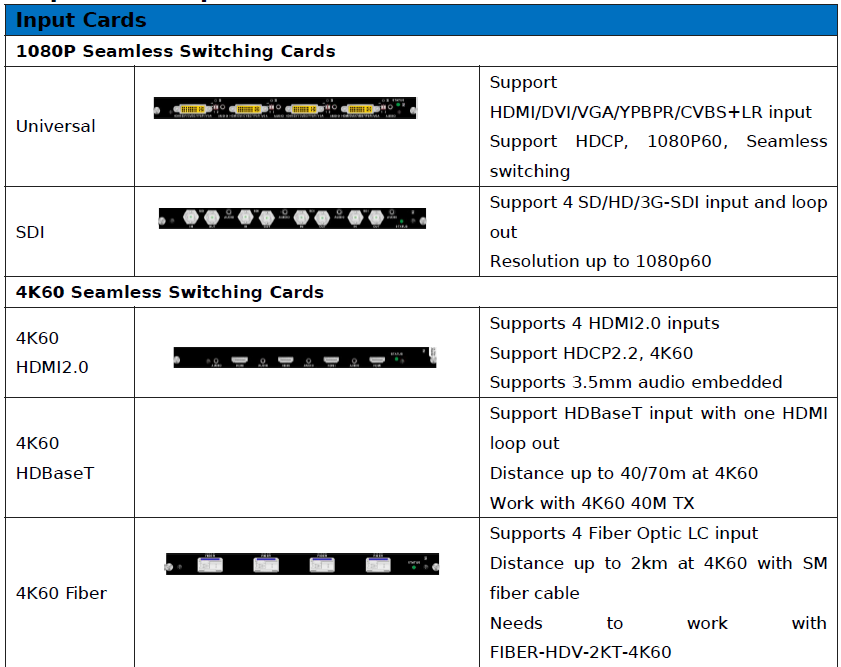
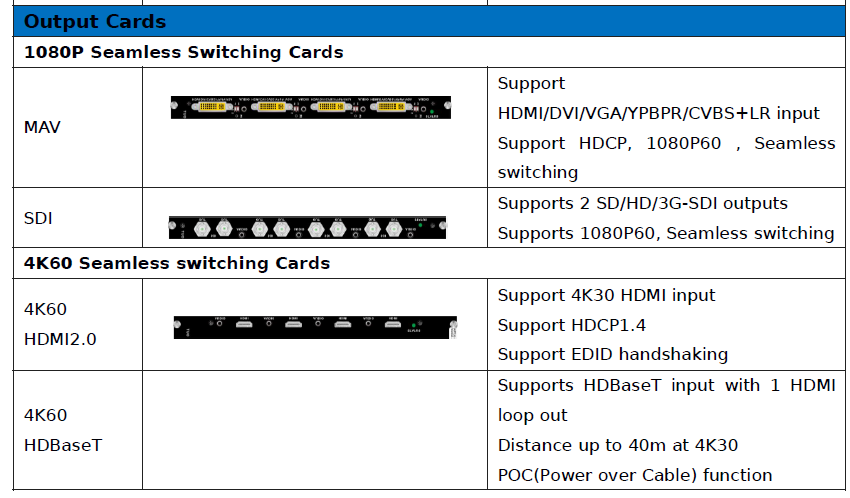
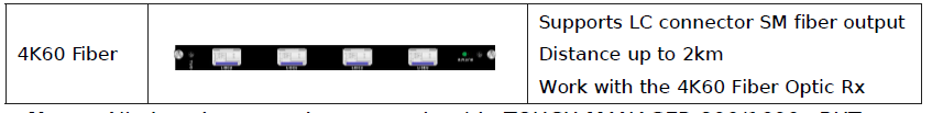
Note: All the above cards can work with TOUCH-MANAGER-800/1600, BUT we suggest to use only 1080P or 4K60 cards on one chassis instead of mixing use 1080P and 4K60 cards together.
Attachment B:D8mzmR7HB7a3HeDqhpRM1iqpzVLEBY4nTf

1080P seamless switching cards:

![]()
[xyz-ips snippet=”download-snippet”]