
belkin Keyboard Mouse Switch

Introduction
The Secure KM SwitchViewing and Interacting with Multiple Systems Simultaneously The Secure KM Switch (models F1DN104K-3 and F1DN108K-3) are engineered for high-security environments where operators require simultaneous interaction with multiple computing systems across different security enclaves. Unlike the traditional Secure KVM, the Secure KM only switches the USB keyboard and mouse between connected inputs, relying on the individual computers to drive their own video displays. The KM is therefore the ideal technology for Command and Control room environments where operators often interact with monitor walls displaying video from multiple systems.
Connections
The Belkin Secure KM Switch can support 2, 4, or 8 computers simultaneously with the use of a single keyboard and mouse. For demonstration purposes, the F1DN104K-3, supporting 4 computers, is used as the reference below.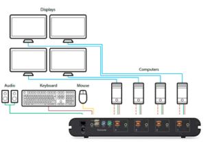 Hardware Connections:– 4x Input Ports (USB Keyboard/Mouse, Audio)– 1x Console Output Port (USB or PS2 Keyboard/Mouse, Audio)– 1x Power Port
Software requirements:– No software is required to be installed on any computer or system unless a connected system has more than one monitor. In cases where connected computers have multiple monitors (the KM can work with computers running Windows® with up to 4 monitors per computer), the Belkin Multi-Monitor Mouse Driver is necessary. The driver can be found at http://www.belkin.com/us/support-article?articleNum=286117– Please note, custom configuration files created in one version of Windows® may not be able to be uploaded to a KM using a different version of Windows®. It is recommended that the same version of the Windows® operating system be used to create and load a custom monitor configuration file to Belkin secure KM switches.
Secure KM Switch Controls and Modes
Keyboard and Mouse
As with Belkin’s Secure KVMs, each of the KM’s keyboard and mouse USB ports is isolated from one another using the same optical data diode technology to eliminate signal leakage. Further, no user data is buffered in the KM that can potentially create security vulnerabilities. These ports use advanced emulation for USB HID commands and physically block any reverse data flow ensuring that malicious code has no way of migrating from an infected peripheral to a secure system and confidential data has no way of being copied onto portable USB media devices.
Mouse
The KM mouse function can be configured to work in either Absolute or Relative mode. In either case, commands are sent to one computer at a time via the optical data diode isolation described above, and the cursors being emulated on the other computers are hidden from view.
Absolute Mode:In Absolute mode, the KM maps all monitors onto the same grid, maintaining the coordinates that reflect the edge of one physical monitor to another. As the cursor is moved from the coordinate at the edge of one physical monitor and onto the coordinate indicating the edge of its neighbor monitor, the KM passes data from the physical mouse to the USB emulation logic for the second computer and paints the cursor onto its corresponding monitor (while simultaneously hiding the cursor on the former monitor). In doing so, it also invokes the Seamless Cursor Switching (SCS) mechanism to seamlessly switch the mouse and keyboard controls to the corresponding input source. The KM’s mouse emulators offer zero delays in switching between computers allowing for an instant response. In keeping with information assurance requirements, the front panel of the KM illuminates the button LED of the new channel to provide constant visual feedback to operators as to which enclave they are working with. In no circumstances will cursor commands be sent to more than one system at the same time.
Relative Mode:In Relative mode, the movement of the mouse is confined to the borders of each computer’s display. The user will then need to select which console to interact with by pressing the appropriate channel selection button on the KM switch as with a traditional KVM.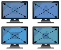
Keyboard
The keyboard connected to the KM interacts with each computer individually and only interacts with one computer at a time. A user can switch the interaction of the keyboard between computers either by pressing the console buttons on the KM or by using the movement of the mouse in Absolute Mode to invoke Cursor Based Switching.
Since mouse and keyboard data flow in a unidirectional data path, any keyboard indicators that require acknowledgment from the computer will not be shown, including LEDs for Caps Lock, Num Lock, or Scroll Lock. For example, when a user presses the Caps Lock key the command will reach the computer and activate all keys as caps, but the computer will not be able to acknowledge the change back to the keyboard to then enable the key’s LED indicator.
Display
The KM provides for a variety of pre-configured monitor configurations that should meet most user requirements. The size, relative positioning, and coordinates of these display configurations are preprogrammed in the KM and can be selected thru administration options. Should one of these presets be inadequate for the application, the F1DN104K-3 and F1DN108K3 also support a custom configuration option using the Belkin KM Configuration utility that can be downloaded from https://www.belkin.com/au/support-article?articleNum=208563
Working with the KM Configuration Tool to Create Custom Monitor Layouts
Requirements:1) Belkin Secure KM with appropriate firmware: · F1DN104K-3 with SC firmware 14090817 or higher · F1DN108K-3 with SC Firmware 09240817 or higher2) Windows-compatible PC (Windows 7 or higher recommended) · Please note that the same version of the Windows® operating system should be used to create and load a custom configuration file3) USB Type-A to USB Type-A cable
Step 1:Download and install Belkin_KM_Tools_Setup-2.5.exe on a Windows® machine. The following items will be installed:1. KMCreator (KM Configuration Utility Version 2.01)2. KMLoader (KMConfigLoader Version 1.0.0.5)3. KM Device driver (Belkin Reg – CDC Driver/Belkin Registration Device)
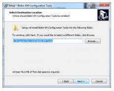
Install the Belkin_KM_Tools_Setup-2.5.exe:a) Review EULA and select Next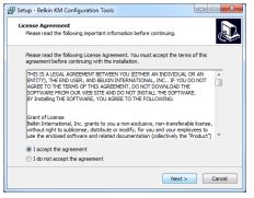 b) Choose the location to install files and select Next
 c) Choose a folder for program icons and select Next to begin the installation
d) Select Install to begin and follow the installation wizard to complete the process.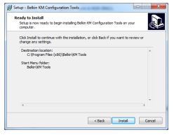
e) Once complete, select Finish Once the installation wizard is complete, shortcuts for KMCreator and KMLoader will be available in the file location you chose.
Step 2:Define monitor configuration with the KM Configuration Utility The KMCreator is used to define the monitor layout and generate a KM configuration file (.kmc file) that will be uploaded to the KM using the KMLoader utility.
Using the KMCreator utility, administrators can define the layout and relevant traits of monitors connected to each computer with different or identical sizes and screen resolutions. The monitors can be deployed in any physical layout. This software also allows the removal of unneeded bridges between monitors that can be used to prevent channel switching via the SCS capability.
Before You BeginA KM configuration file is based on the number of computers that will be connected to the KM and the number, size, and resolution of the monitors each computer will have associated with it.
NOTES: 1) The KMCreator and KMLoader software do not need to be loaded on each computer.2) The software should be installed on an external computer and used to upload the configuration to the KM. If one computer is used to create the configuration file and another used to load it, it is recommended that the same version of the Windows® operating system be running on both computers. The KMCreator and KMLoader software are not needed after the desired configuration has been loaded onto the KM.1) Create a new Project Each KM configuration file is called a “KM Configuration Project”. For every setup, you will be required to create a new project. Click “Back” to return to the previous stage, at any point during the configuration process.
- Open KMCreator
- Select “New Project”
 2) Enter Project DetailsPlease enter the requested information in the following manner:
 - Project Name The name can be a combination of English characters or numbers. It is advised to use a name that will be reflective of the configuration for example: “Dealer 3 5 monitors”, “Generic Workstation 7”. The project name can be read from the KM after loading.
- Product Model The product model can be found on the product label of the KM switch. The Belkin Secure KMs come in 4, and 8 input models.
- Mouse Speed This is the default mouse speed for all systems. Changing the mouse speed on each computer will not affect the KM mouse speed.
- Mouse Acceleration Same as above.
- Number of Computers The total number of computers that will be connected to the KM for this configuration.
- Click “Next Step“
 2) Enter Project DetailsPlease enter the requested information in the following manner:
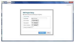
3) Enter DescriptionAdd a description for the project. The description will appear in the configuration file (.kmc) and can help differentiate one configuration from another when working with multiple potential configurations.
4) Monitor ConfigurationFor each computer, define the number of monitors connected to the computer by selecting it from the drop-down menu “Number of Displays”. The maximum number of possible displays is limited to four per computer. Once the number of monitors is selected, you will be able to enter the size and native resolution for every monitor.Note: If a certain monitor is set to portrait orientation, the Native resolution should be entered accordingly. For example, for a monitor with a native screen resolution of 1680×1050 which is used in portrait orientation, enter the resolution as 1050×1680.
Computer 1 Setup
Enter information about each display connected to this computer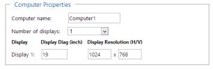
Working with Multiple Monitors per ComputerWhen using more than one display per computer, Microsoft Windows’ display options must be synchronized with the KM for proper operation.
Microsoft Windows maps monitor into a virtual desktop, allowing a user to move the mouse cursor from one monitor to the other. The KM must understand how these monitors are mapped in a Windows desktop environment and which monitor defines the edge between channels so as to invoke SCS channel switching. This procedure must be done for each PC with multiple monitors.
1) To begin, open the display settings dialog on the Windows PC.· Right-click on the desktop and select Display Settings or navigate to Control Panel, Display Settings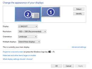 The following instructions are based on Windows 7, but can also be used with Windows 8 and Windows 10. 2) In the KM configuration dialog you will be asked to provide information regarding your primary display. The primary display is referred to as “main display” in the Windows “Screen Resolution” dialog. You can determine which monitor is the main display by selecting it in the array of displays as shown below.
 3) Select the appropriate number of monitors in the KMCreator dialog for Computer 1. Selecting more than 1 monitor exposes the additional details.
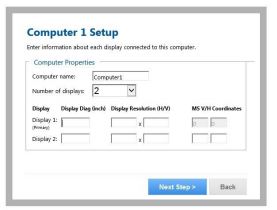 4) Enter the details for your primary (main) display as requested in the dialog. 5) Enter the details for the secondary display.a. To find the vertical and horizontal coordinates, select the secondary monitor in the Windows Display Settings dialog box and move it slightly. The Vertical and Horizontal values of the monitor will appear in Windows 7 and Windows 8 computers per the below screen capture:
 b. Windows 10 hides these coordinates, requiring the administrator to calculate the relative position as follows:i. The Primary monitor has XY coordinates 0,0 mapped to its upper left-hand corner.ii. If the monitor is a 1920×1080 monitor, the coordinates of the second monitor immediately to its right will start at 1920,0 assuming both monitors are in landscape mode. Enter 1920,0 for the secondary monitor in the KMCreator dialog box
5) Place the Displays and Create the channel associations in the KMCreator interfaceIn this step, we will create a mapping of the monitors at an operator’s desk, defining their relative position to each other and the associated channels for SCS switching.
- Each display is identified by the computer number and monitor number that was entered previously.
- Monitors can be connected or have some distance all based on the actual geometry required.
- Once the monitors are aligned, a yellow “bridge” will appear indicating where the KM will switch mouse/keyboard/audio control from one channel to the other.
- Clicking on one of the bridge areas will toggle it off, which will prevent the SCS channel switch, requiring the operator to press the appropriate channel button on the front of the KM switch.
- To re-enable the bridge between monitors, drag one monitor toward the desired neighboring monitor, having them touch each other at the appropriate edge. Pull apart the monitors, and the bridge will appear between the monitors again.
Examples:Example 1: The following setup creates a corridor from the top right of monitor 2 computers 2 to the bottom left of monitor 1 computer 1. Dragging the mouse through the portion of the monitors connected by the yellow bridge will switch channels between channels 1 and 2. Attempting to drag the mouse through one of the areas depicted by the red highlights in the figure below will block SCS from switching channels.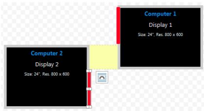
Example 2: Both configurations below create identical setups in which the mouse cursor moves from the right of computer 2 to the left of computer 1.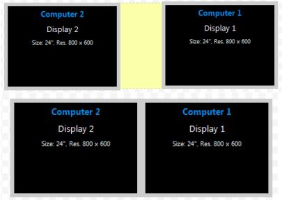 Example 3: The setup shown in Fig A below will not invoke an SCS-based channel switch as there is no bridge between the two monitors. However, touching the monitors per Fig. B creates a bridge and invokes SCS-based channel switching.
Example 4: The two setups below are identical except that on the right setup, the user chose to prevent the mouse cursor from moving from Computer 2, Display2 to Computer 1, Display 1 by clicking on the yellow bridge to toggle it off.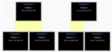 Note the following considerations when working with systems that have more than one monitor per computer:
- The monitor orientation in Windows must match the monitor orientation in the KMCreator utility.
- All displays connected to the same PC must be positioned as touching each other in the KMCreator interface. Do not depict distance between two displays connected to the same computer.
6) Complete Setup
Once the monitor configuration is defined, press “Complete Setup” to generate the .kmc file.
Step 3: Load configuration file to the KM
KMLoader allows you to load the configured .kmc file (created per the procedure in Step 2 into the Secure KM Switch. If using a different computer to create the .kmc file and a second one to upload the file, it is recommended that both computers run on the same version of the Windows® operating system.
Setting up the KM Switch for Loading the Configuration (.kmc) File The KM switch is configured through a USB A to USB A cable connected from a PC containing the KM Loader to one of the consoles USB ports on the KM. The USB A to USB A cable is not included with the KM and must be purchased separately.1. For the F1DN104K-3, disconnect the mouse from the Console USB mouse port of the KM switch and connect the USB A to USB A cable from the PC to the mouse port on the KM.2. For F1DN108K-3, disconnect the mouse from the Console USB mouse port of the KM switch and move the keyboard to the console USB mouse port then connect the USB A to USB A cable from the PC to the console USB keyboard port of the target KM Switch.3. Put the KM switch into programming mode by typing on the connected keyboard left Ctrl, right Ctrl, followed by the L. The KM Switch will click several times audibly and all LEDs will flash simultaneously to indicate that the unit is in programming mode.4. Check that the Belkin Registration Device has been installed properlya) Open Device Manager on Windows PCb) Look for Ports (COM & LPT) and then Belkin Registration Device or USB Serial Device. If Device Manager shows either, the driver was installed correctly and you can proceed to the “Loading the Utility” step. If not, follow the below process to first install the driver.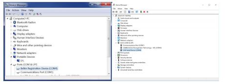 c) If the Belkin Registration Device is not present, look for Universal CDC Loader under Other Device Manager:
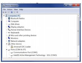 d) Right-click on Universal CDC Loader and choose Update Driver Sofware:
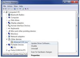 e) Select Browse my Computer for Driver Software from the next dialog:
 f) Select Let Me Pick From a List of device drivers on my computer on the next dialog:
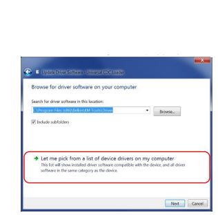 g) Select Ports (Com & LPT) from the next dialog and click Next
h) Select Have Disk on the following dialog box: i) Navigate to the folder that the Belkin Tools were installed in (C: Program Files (x86)BelkinKM ToolsDriver) and select OK:
 j) Select the BelkinRD file and select Open:
 k) Select the Belkin Registration Device on the subsequent dialog and select Next, select Yes if a dialog asks to confirm the installation, and Install if another dialog requests confirmation.
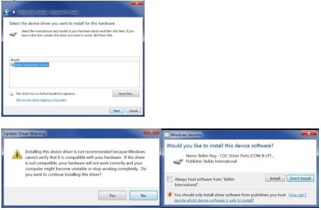 l) Once complete, check Device Manager for Belkin Registration Device again to ensure the driver was successfully installed. Device Manager should look similar to the following image:
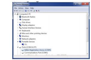
Loading UtilityOnce the KM Switch is in programming mode and connected to the PC:
- Open the KM Configuration Loader utility
- Make sure the KM Loader window shows “Device Connected” on the lower-left corner.
- Select COM port “COM # (Belkin Registration Device/USB Serial Device)” (COM port # will differ from system to system).
- Select port configuration “4” for F1DN104K-3, “8” for F1DN108K-3.
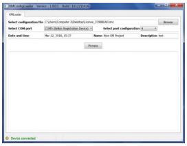
Loading a Configuration file1) Select Browse to load Configuration File in “Select configuration file” field 2) Locate your .kmc configuration file3) Select “Process”, If successful, KM Configuration Loader Tool Window will show “Configuration file has been successfully loaded to device”‘4) Power cycle the device (for the F1DN108K-3, ensure you also remove the USB A to USB A cable)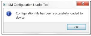 5) Power cycle the KM then type left CTRL, left CTRL, F11, F12 to load the new configuration and begin use.
References
[xyz-ips snippet=”download-snippet”]