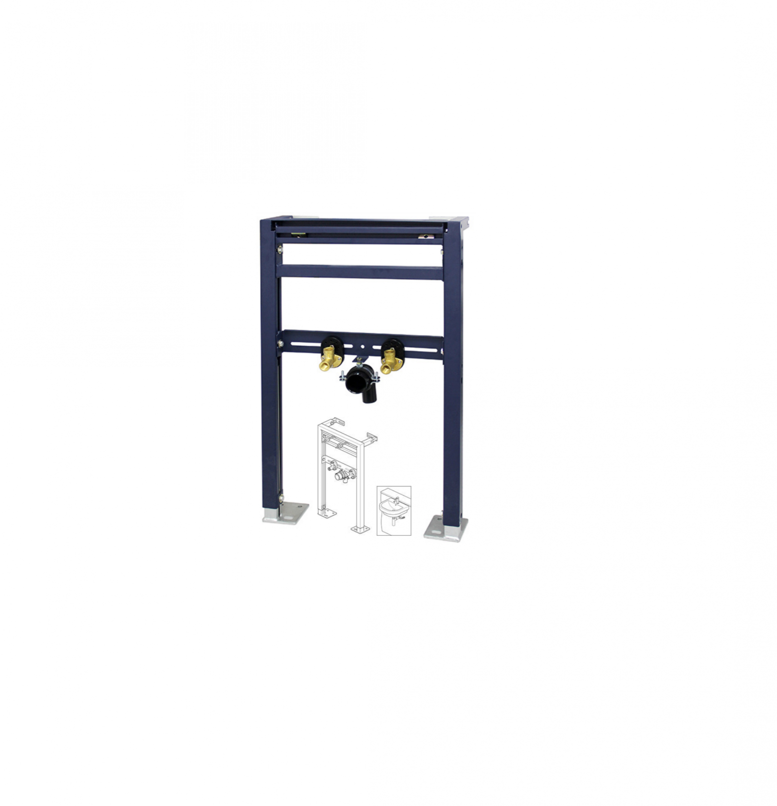
BERNSTEIN G30014A Wash basins
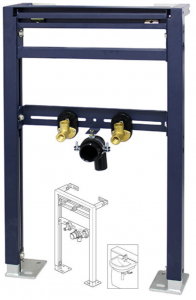
OVERVIEW
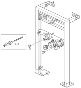
- Wall Adjustment Bolts x2
- Wall Brackets x2
- Height Adjustment Bolts x2
- Floor Brackets
- Connection Height Adjustment Bolts x2
- Connection Support Bar x1
- Hot Water Inlet Elbow x1
- Cold Water Inlet Elbow x1
- Waste Outlet Elbow x1
- Basin Fixing Bolts, Nuts & Washers x2
- Waste Pipe Seal x1
- Blanking Plugs x2
ASSEMBLY
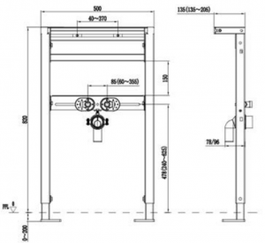
Plan the position of the basin. The recommended basin height is 850 mm to the front rim.The distance from the wall may depend on the space requirements for a cistern if a toilet is being installed in the same run.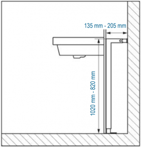
Place the frame against the wall in the required position.Loosen the height adjustment bolts, set to the required height, check the frame is level and retighten the bolts.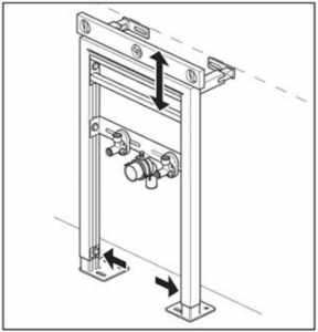
Set the required distance from the wall. Loosen the wall adjustment bolts, set to the required distance, check the frame is vertical and retighten the bolts.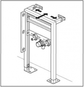
Mark the fixing positions on the wall and floor. Remove the frame and drill suitable holes for the fixings.Attach the frame to the wall and floor using suitable fixings. Check the frame is level in all directions.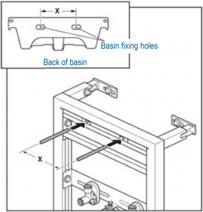
Attach the waste, trap and mixer/tap, to the basin.Note: A typical Bath store adjustable chrome plated bottle trap is shown (designs may vary). The trap height is vertically adjustable, adjust the trap to allow some up and down adjustment in the final assembly.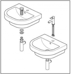
Carefully lift and position the basin onto the basin fixing bolts. Loosen the connection height adjustment bolts, set the connection support bar to the required height to line up with the waste outlet elbow. Retighten the bolts and remove the basin.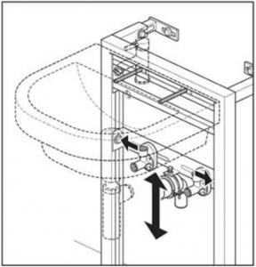
Prepare and connect the waste water outlet (a push-fit waste is recommended).Note: The waste outlet elbow can be rotated to take the waste water pipework by loosening the bolts shown. Secure the pipework in the void.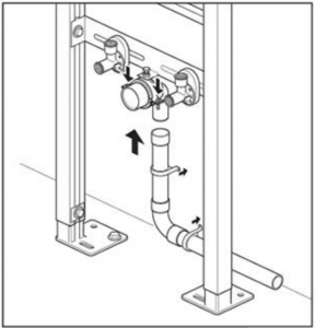
Loosen the hot and cold inlet elbows (using the nut at the rear), set to the required distance apart and retighten.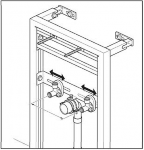
Connect the hot and cold pipework to the inlet elbows (Ø ½“), screw the blanking plugs into the outlets. BSP female threaded outlets may need extending using male nipples. The hot and cold inlet elbows can be rotated as required to suit your pipework. It is essential that isolation valves are fitted at this point.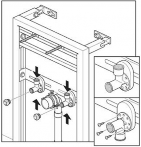
Push fit the waste pipe seal into the waste outlet elbow.Build the partition wall, making the holes for the bolts and pipes as small as possible. If required, tile the surface or apply the finish now. Lubricate the inside of the waste pipe seal and push fit the basin waste pipe fit into the waste outlet elbow.|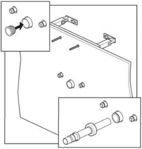
Carefully position the basin on the wall, mark a line level with the end of the waste trap outlet onto the basin waste pipe. Remove basin and waste pipe, add a further 25 mm to the length of the waste pipe and cut to length. Some extension pipes are stepped at the trap end, ensure the correct end is cut and any burrs are removed. Refit waste pipe into waste outlet elbow. The above applies to the ´Bathstore cylindrical trap`.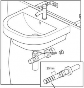
Carefully position the basin onto the fixing bolts, lining up the waste connections at the same time.Under the basin, place the plastic and metal washers onto the bolts and secure with the nuts.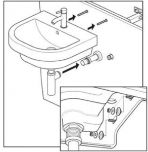
Secure the outlet pipe onto the trap and slide the cover up to the wall.Fully tighten all connections.Remove the blanking plugs from the outlets.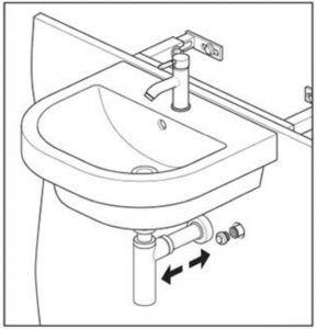
Connect the hot and cold flexible pipes to the inlet elbows, adaptors may be required.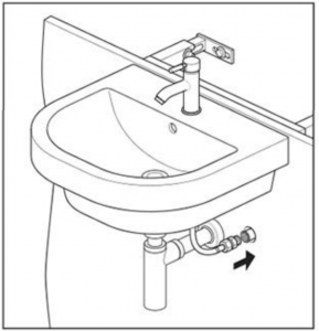
Finish the installation by water testing the inlet and outlet connections in the void.Note: You must ensure there is access to the connections in the void. The installation is now completed by fitting the access lid to the void.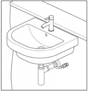

[xyz-ips snippet=”download-snippet”]