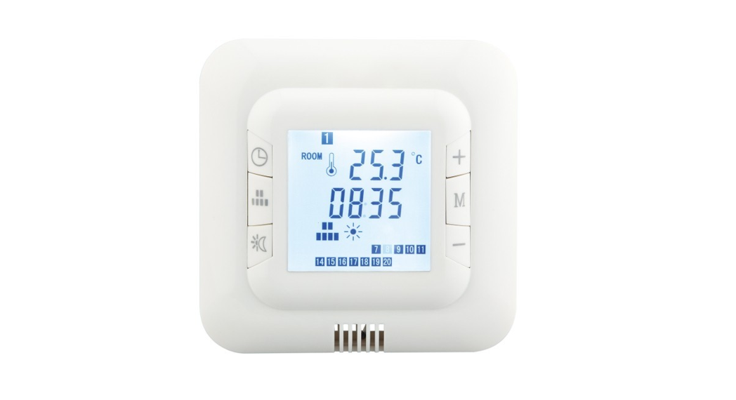
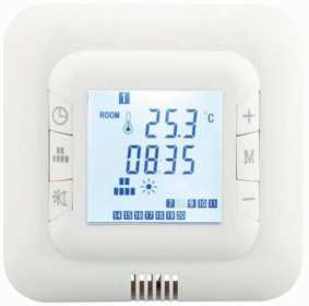
![]() DIGITAL THERMOSTAT
DIGITAL THERMOSTAT
 MONTAGEANLEITUNG – I / 2018ASSEMBLY INSTRUCTIONS
Mounting of the floor sensor
The floor sensor should be installed within an approved nonconductive installation pipe in accordance with EN 61386-1, which is embedded in the floor.The pipe (flexible conduit) should be placed as high as possible in the subfloor.The floor sensor should be located equidistant between two runs of the heating element with the tip at least 300mm away from the outside edge of the heater. The enclosed 3-meter sensor cable can be extended up to 50m by means of a separate cable.The installation pipe must not contain any other cables, such as the supplies to the heating wire.The switching peaks of such current supply lines may create interfering signals that prevent optimum thermostat function. The heating supply cable should be placed in a separate pipe.In the event of sensor failure, replacement of the sensor can be carried out with ease providing the sensor is installed within the flexible conduit.The floor sensor should never cross the heating element.
Electrical Connection
Electrical connections are to be made as detailed in the diagram. The circuit supplying this controller must be protected by a 30mA RCD. All electrical connections must be performed by a fully qualified and part P-certified electrician. Any doubts surrounding the installation of this controller should be passed to the distributor prior to installation. Testing of all under-floor heating systems should take place prior to floor coverings being installed.
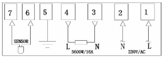
| 1 Live from mains2 Neutral from mains3 Neutral to heaters4 Live to heaters | 5 Earth from heaters & mains6 White wires from the sensor7 Black wire from the sensor |
Remove this sensor from the circuit before performing any high voltage insulation tests.IMPORTANT: ALWAYS DISCONNECT THE MAINS SUPPLY VIA THE SWITCH IN THE MAIN FUSE BOARD, CONSUMER UNIT BEFORE COMMENCING ANY ELECTRICAL WORK. WHEN CONNECTING CABLES TO THE THERMOSTAT, ENSURE THAT ALL TERMINAL SCREWS ARE FULLY TIGHTENED AND THAT EARTH WIRES ARE SLEEVED AND THAT NO BARE WIRES ARE SHOWING.
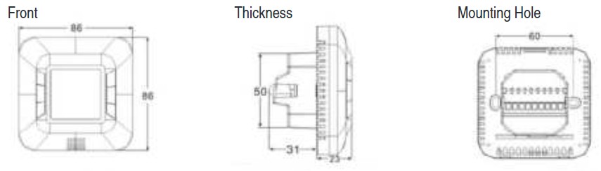
Mounting & Installation
 |
||
 |
 |
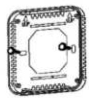 |
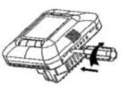
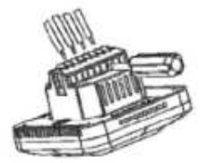
| Release the front of the thermostat by inserting a small flat screwdriver into the 2 slots on the base. | Make electrical connections as detailed in the previous section. | Mount base part of thermostat onto either a BS recessed or surface mounted box. |
Technical Data

| Voltage: | AC230V ± 10% 50/60HZ |
| Power Consumption: | 5W |
| Setting Range: | 5 ~ 30ºC |
| Floor overheating Protection: | 30 ~ 80˚C (factory set @ 65˚C) |
| Protective housing: | IP20 |
| Housing Material: | ABS + PC fire-resistant |
| Certification: | CE |
| Floor Sensor: | Rubber-Thermoplastic NTC 10K Sensor |
| Internal Sensor: | NTC 10K |
Sensor Selection
The thermostat is factory preset to use the room and floor temperature sensors. The following options are available.To change, press M for 3 seconds then M once more. Option can then be selected by the + / – buttons.
|
rS |
Room sensorONLY |
Heating will be switched on by the thermostat when the room temperature falls below the programmed temperature.There is NO LIMIT on the temperature the floor can reach. |
|
FS |
Floor Sensor |
Heating will be switched on by the thermostat when the floor temperature falls below the programmed temperature.* |
|
rFS |
Room andfloor sensor |
Heating will be switched on by the thermostat when the room temperature falls below the programmed temperature. The thermostat will cut power to the heating if the floor reaches a temperature higher than the programmed level. This is factory set at 65˚C This can be re-programmed by the user at a level between 30˚C – 80˚C. RECOMMENDED MAX: 40˚C |
*If this thermostat is to be used with any underfloor heating system designed for floor coverings other than ceramic, porcelain, or stone floortiles, the ‘floor sensor only’ option should be selected.The (Comfort)![]() , (Energy save)
, (Energy save)![]() , and (Holiday)
, and (Holiday) ![]() modes all need to be checked to ensure that the operating temperatures do not exceed the values given by your heating/floor covering supplier. These temperature levels can be amended by holding for 3
modes all need to be checked to ensure that the operating temperatures do not exceed the values given by your heating/floor covering supplier. These temperature levels can be amended by holding for 3 ![]() seconds.The first value that can be changed is the holiday mode. Press once more (quickly) to amend the energy save value, and once more for the comfort value.
seconds.The first value that can be changed is the holiday mode. Press once more (quickly) to amend the energy save value, and once more for the comfort value.
Thermostat Programming
Your new thermostat has the following 3 modes. To manually select a specific mode press M.
|
Comfort mode |
 |
Select this mode to turn the under-floor heating on. The heating will operate at the preset temperature.To alter the preset temperature hold |
|
Energy-saving mode |
 |
Select this mode to turn the under-floor heating down to a lower preset temperature. This temperature can be set low enough to mean the heating is effectively turned off. To alter the preset temperature hold |
|
Holiday mode |
 |
Select this mode to set the heating to a very low level whilst the room is unoccupied for a long period of time.This mode should be selected to avoid frost damage whilst on holiday. To alter the preset temperature hold |
Whilst the thermostat is operating in any of the modes above, the temperature can be manually altered by pressing the + or – buttons. The set temperature will then revert back to the pre-set level at the next change of mode.
Date & Time Settings
To set the correct date & time press and hold for ![]() 3 seconds. Minutes will flash, press + / – to alter.Press once again to alter hours (24-hour clock).Press once again to change weekday.The numbers from 1 to 7 at the top of the screen represent Monday to Sunday.
3 seconds. Minutes will flash, press + / – to alter.Press once again to alter hours (24-hour clock).Press once again to change weekday.The numbers from 1 to 7 at the top of the screen represent Monday to Sunday.
7 Day Automatic mode
To select the 7-day timer mode press M until ![]() is displayed on the LCD screen. The thermostat will then switch between comfort & energy-saving mode (On/Off) automatically according to the day & time settings. Each day of the week can be programmed with individual settings.To set up the automatic mode, press & hold for 3
is displayed on the LCD screen. The thermostat will then switch between comfort & energy-saving mode (On/Off) automatically according to the day & time settings. Each day of the week can be programmed with individual settings.To set up the automatic mode, press & hold for 3 ![]() seconds.To select the day of the week to be programmed press
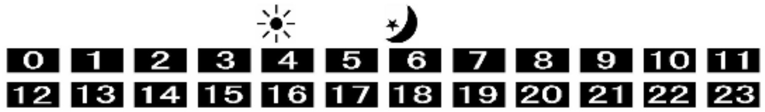
seconds.To select the day of the week to be programmed press![]() .The bottom of the screen will show the following pattern of 24 numbered surfaces. Each field represents a 1 hour period of a 24-hour cycle. Each of these 1 hour periods can be programmed to comfort or energy-saver (On/Off) mode.
.The bottom of the screen will show the following pattern of 24 numbered surfaces. Each field represents a 1 hour period of a 24-hour cycle. Each of these 1 hour periods can be programmed to comfort or energy-saver (On/Off) mode.
To make changes to the timed program, press + / – to select the 60 minute period. Then press ![]() to select the mode.Pressing + or – will copy the selected mode from the previous 60 minute period.Whilst programming, an inactivity of 5 seconds will save the settings entered & the thermostat will return to normal operational mode.Advanced Settings
to select the mode.Pressing + or – will copy the selected mode from the previous 60 minute period.Whilst programming, an inactivity of 5 seconds will save the settings entered & the thermostat will return to normal operational mode.Advanced Settings
To enter advanced settings press and hold M for 3 seconds. Press M once again for each numbered function.
- Temperature Calibration. If an accurate temperature readout from the room or floor differs from the readout on thethermostat, providing the sensor has been checked against the stated resistance values, the thermostat can be calibrated using this function.The range is -8˚C ~+8˚C.
- Sensor Selection. See the beginning of the Operating Instructions section for details.
- When operating the thermostat with the rFS sensor selection, the room temperature will display on the thermostat.This function allows the user to see the current floor temperature.
- When operating the thermostat with the rFS sensor selection, this function allows the user to amend the maximum temperature the floor can reach. If the floor temperature exceeds this over-heating protection set-point, ALARM will flash on the screen and the heating output will cut out.
Safety Information
WARNING: RISK OF ELECTRIC SHOCK. Disconnect the power supply before making electrical connections. Contact with components carrying hazardousvoltage can cause electrical shock and may result in severe personal injury or death.This thermostat is not a safety device and should only be used with safety certificated floor heating systems suitable for their specific purpose. In order to avoid damaging your flooring, ensure the correct sensor selection & operating temperatures are selected during the programming process.

STATEMENT
This instruction should only be considered as a standard manual. Modifications applied to an updated version of the product might not be mentioned inside this document. In this case, please just use the manual as a reference.The company reserves modification rights.
[xyz-ips snippet=”download-snippet”]