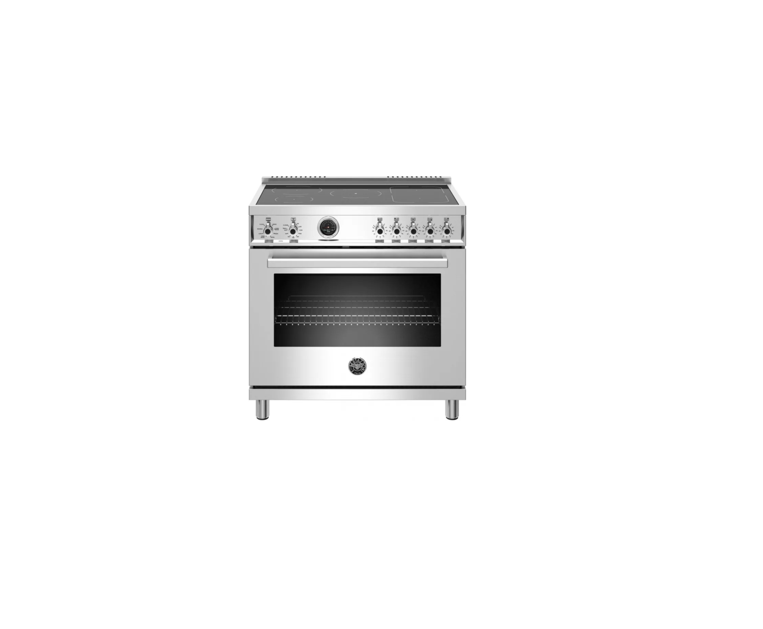
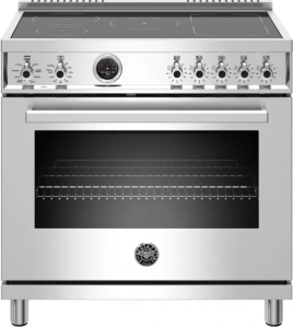
BERTAZZONI MAST365INMXE 36 inch Stainless Steel Free Standing Electric Range
ModelsMAST365INMXEMAST365INSXT
ModelsPROF304INMXEPROF304INMXTPROF304INSARTPROF304INSBITPROF304INSGITPROF304INSNETPROF304INSROTPROF304INSXTPROF365INSARTPROF365INSBITPROF365INSGITPROF365INSNETPROF365INSROTPROF365INSXT
WARNINGS
To ensure proper and safe operation, the appliance must be properly installed and grounded by a qualified technician. DO NOT attempt to adjust, repair, service, or replace any part of your appliance unless it is specifically recommended in this manual. All other servicing should be referred to a qualified servicer.
FOR THE INSTALLER: Before installing the Bertazzoni appliance, please read these instructions carefully. This appliance shall be installed in accordance with the manufacturer’s installation instructions. Leave these instructions with the owner, who should save them for local inspector’s use and for future reference. DO NOT remove permanently affixed labels, warnings, or plates from product. This may void the warranty.
Installation must conform with all local codes. This range is NOT designed for installation in manufactured (mobile) homes or recreational park trailers.DO NOT install this range outdoors.
This appliance must be properly grounded. Grounding reduces the risk of electric shock by providing a safe pathway for electric current in the event of a short circuit.
| Warning!To avoid risk of property damage, personal injury or death; follow information in this manual exactly to prevent a fi re or explosion. |
| Warning!To avoid risk of property damage, personal injury or death; follow information in this manual exactly to prevent a fire or explosion. DO NOT store or use gasoline or other flammable vapors and liquids nearby this or any appliance.
NOTE: Installation and service must be performed by a qualified installer, service agency or the gas supplier. |
| DANGER!!! ELECTRIC SHOCK HAZARD!!!To avoid risk of electrical shock, personal injury or death, verify that the appliance has been properly grounded in accordance with local codes or in absence of codes, with the National Electrical Code (NEC). ANSI/NFPA 70- latest edition. |
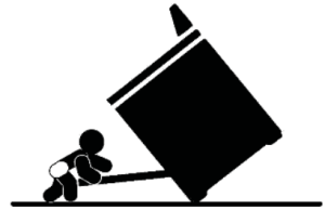 Warning – tipping hazardChildren and adults can tip over the range if it has not been secured. This may lead to fatal injuries. To reduce the risk of the appliance tipping, it must be secured and connected using the anti-tip device according to the installation instructions. Warning – tipping hazardChildren and adults can tip over the range if it has not been secured. This may lead to fatal injuries. To reduce the risk of the appliance tipping, it must be secured and connected using the anti-tip device according to the installation instructions. |
Re-engage the anti-tip device if the range is moved. Do not operate the range without the anti-tipdevice in place and engaged. Do not use the range if the anti-tip device has not been properly installed and engaged. See installation instructions for details.
Failure to observe the information contained in the installation instructions can lead to serious or fatal injuries for children and adults.
DO NOT lift the range by the oven door’s handle, as this may damage the door hinges and cause the door to fit incorrectly.DO NOT lift the appliance by the range’s control panel.The unit is heavy and should be handled accordingly. Proper safety equipment such as gloves and adequate manpower of at least two people must be used in moving the range to avoid injury and to avoid damage to the unit or the floor. Rings, watches, and any other loose items that may damage the unit or otherwise might become entangled with the unit should be removed. Hidden surfaces may have sharp edges. Use caution when reaching behind or under appliance. DO NOT use a hand truck or appliance dolly on the back or front of the unit. Handle from the side only.
DATA RATING LABEL
The data rating label shows the model and serial number of the range. It is located under the control panel and in the last page of this manual
BEFORE INSTALLATION
- This appliance shall only be installed by an authorized professional.
- This appliance shall be installed in accordance with the manufacturer’s installation instructions. This appliance must be installed in accordance with the norms & standards of the country where it will be installed.
- The appliance, when installed, must be electrically grounded in accordance with local codes or, in the absence of local codes, with the National Electrical Code, ANSI/NFPA 70.
All opening and holes in the wall and floor, back and under the appliance shall be sealed before installation of the appliance.
Room ventilationAn exhaust fan may be used with the appliance; in each case it shall be installed in conformity with the appropriate national and local standards. Exhaust hood operation may affect other vented appliances; in each case it shall be installed in conformity with the appropriate national and local standards.
| WarningThis appliance should not be installed with a ventilation system that directs air in a downward direction toward the range. This type of ventilation system may cause ignition and combustion problems with the appliance resulting in personal injury, property damage, or unintended operation. Ventilating systems that direct the air upwards do not have any restriction. |
Do not use aerosol sprays in the vicinity of this appliance while it is in operation.
VENTILATION PREPARATION
This range will best perform when installed with Bertazzoni exhaust hoods. These hoods have been designed to work in conjunction with the Bertazzoni range and have the same finish for a perfect look.Before installation of the exhaust hood, consult local or regional building and installation codes for additional specific clearance requirements.Refer to the range hood installation instructions provided by the manufacturer for additional information.
Select Hood and Blower Models:
- For wall installations, the hood should be equal or larger width than the range. Where space permits, a hood larger than the range may be desirable for improved ventilation performance.
- For island installations, the hood width should overhang the range by a minimum of 3″ (76 mm) on each side.
Hood Placement:
- For best removal of smoke and odors, the lower edge of the hood should be installed between 25 1/2″ (65 cm) and 31 1/2″ (80 cm) above the range cooking surface.
- If the hood contains any combustible materials (i.e. a wood covering), it must be installed at a minimum of 36″ (914 mm) above the cooking surface.
Consider Make-Up Air:Due to the high volume of ventilation air, a source of outside replacement air is recommended. This is particularly important for tightly sealed and insulated homes. A qualified heating and ventilating contractor should be consulted.
SPECIFICATIONS

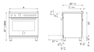
CLEARENCE DIMENSIONS
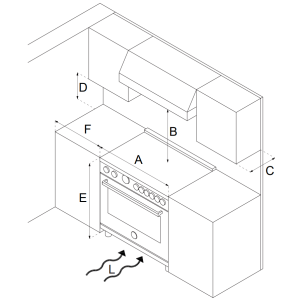
Installation adjacent to kitchen cabinetsThis range may be installed directly adjacent to existing countertop high cabinets (36″ or 91.5 cm from the floor).For the best look, the worktop should be level with the cabinet countertop. This can be accomplished by raising the unit using the adjustment spindles on the legs.ATTENTION: the range CANNOT be installed directly adjacent to kitchen walls, tall cabinets, tall appliances, or other vertical surfaces above 36″ (91.4 cm) high. The minimum side clearance in such cases is 6″ (15.2 cm).Wall cabinets with minimum side clearance must be installed 18″ (45.7 cm) above the countertop with countertop height between 35 ½” (90.2 cm) and 37 ¼” (94.6 cm). The maximum depth of wall cabinets above the range shall be 13″ (33.0 cm).
Cabinet
|
A |
30’’ (76,2 cm |
|
B |
36’’ (91,5 cm) hood with combustible materials |
|
C |
13’’ (33,0 cm) |
|
D |
18’’ (45,7 cm) |
|
E |
35’’ 1/2(90,2 cm) / 37” 1/4 (94,6 cm) |
|
F |
6’ (15,2 cm) |
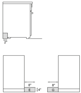
If installing toekick, verify that the sum of the cutout areas equal the recommended ventilation (L)30” area 40 sq. inches ( 25840 mm2)36” area 51 ½ sq. inches ( 33107 mm2)48” area 73 ½ sq.inches ( 47547 mm2)
Metal hood
| A | 30’’ (76,2 cm) |
| B | 25 1/2’’(65 cm) and 31 1/2’’ (80 cm) |
| C | 13’’ (33,0 cm) |
| D | 18’’ (45,7 cm) |
| E | 35’’ 1/2(90,2 cm) / 37” 1/4 (94,6 cm) |
| F | 6’ (15,2 cm) |
| G | 12”(30,50 cm) |
| H | 1” 9/16(4 cm) |
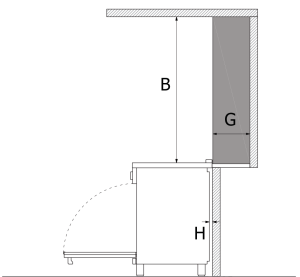
Shaded area behind range indicates minimum clearance to combustible surfaces, combustible materials cannot be located within this area.12” (305 mm) min. to combustible surface with Flush Island Trim For Flush Island installations, counter surface should have a cantilever edge meeting the back section of the Flush Island Trim accessory.
INSTALLATION REQUIREMENTS
ELECTRICAL
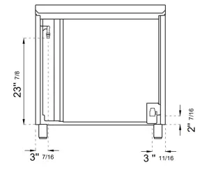
A properly-grounded horizontally- mounted electrical receptacle should be installed no higher than 3″ (7.6 cm) above the floor, no less than 2″ (5 cm) and no more than 8″ (20,3 cm) from the left side (facing product). Check all local code requirements.
![]() installation area for the connection
installation area for the connection
ELECTRICAL CONNECTION
| Warning!ELECTRICAL SHOCK HAZARDDisconnect electrical power at the circuit breaker box or fuse box before installing the appliance.Provide appropriate ground for the appliance.Use copper conductors only. Failure to follow these instructions could result in serious injury or death. |
Electrical groundingThis appliance is equipped with a four-prong plug for your protection against shock hazard and should be plugged directly into a properly grounded socket. Do not cut or remove the grounding prong from this plug.
| Caution Label all wires prior to disconnecting when servicing controls. Wiring errors can cause improper and dangerous operation. Verify proper operation after servicing. |
The appliance shall be connected to a single phase electric line rated at 120/208Vac or 120/240Vac and 60Hz frequency.
|
Type |
Voltage | Circuit rating |
Electrical supply |
|
30” IND- DFM |
120/208V120/240V | 10300W 46A11000W 48A | 40A40A |
| 30” IND- DFS | 120/208V120/240V | 11700W 53A13000W 56A |
40A40A |
|
36” IND- DFM |
120/208V120/240V | 14000W 62A14800W 64A | 40A40A |
| 36” IND- DFS | 120/208V120/240V | 15600W 70,5A17000W 73,5A |
50A50A |
Install a suitable electric power supply receptacle connection type NEMA 14-50R able to support a load of at least 30 A (per line) according to local code requirements. For four or three wires power supply connection system see diagram below.
FOUR-WIRE CONN.RECEPTACLE NEMA 14-50R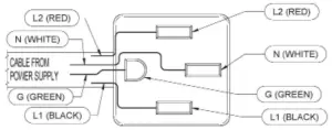
– FOUR Wires connection:
-Connect the L1 receptacle terminal to the incoming BLACK electrical supply wire (L1-hot wire)-Connect the L2 receptacle terminal to the incoming RED electrical supply wire (L2-hot wire)-Connect the NEUTRAL receptacle terminal to the incoming NEUTRAL (WHITE) electrical supply wire -Connect the GROUND receptacle terminal to the incoming GROUND (GREEN) electrical supply wire
DO NOT USE EXTENSION CORDS WITH THIS APPLIANCE AS IT MAY RESULT IN FIRE, ELECTRIC SHOCK OR OTHER type of PERSONAL INJURY.
The appliance is equipped at the factory with an electric supply cord set 4 wires type with ring terminals (L1, L2, N, Ground) suitable for range use UL/CSA listed type SRDT/DRT 2x6AWG (L1, L2)+2x8AWG (N, G) rated 300V, 40 or 50A with fused plug type NEMA 14-50P; cable length 1,5 m.; in case the supply cord set must be replaced, it shall be replaced with an identical set having the same technical specs and following carefully the instructions and diagrams below:
WIRING DIAGRAM
The electric wiring diagrams and schematics are attached behind the range, and should not be removed except by a service technician, then replaced after service.
DFM
DFS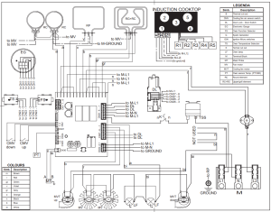
INSTALLATION
APPLIANCE INSTALLATION
Unpacking the range
- Remove all packing materials from the shipping pallet but leave the adhesive-backed foam layer over brushed-metal surfaces to protect it from scratches until the range is installed in its final position. Only the film on the side panels should be removed before inserting the range between the cabinets.
- Examine the appliance after unpacking it. In the event of transport damage, do not plug it. Take pictures of the damage and report it immediately to the freight forwarder.
- Remove the oven door(s). This will reduce the weight of the range. The grates, griddle plate, burner caps, and oven racks should be removed to facilitate handling.
- Before moving the range, protect the floor to prevent damage.
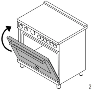
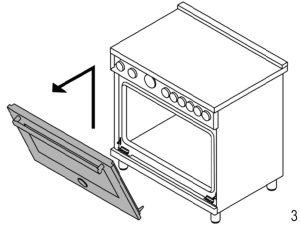
REMOVING THE OVEN DOOR
Prepare the door for removal. Flip up the locking clamps on each door hinge. Slowly shut the door until the protruding clamps stop the movement.
Pull oven door upwards and remove.
Do not lift or carry the oven door by its handle!This may damage the hinges.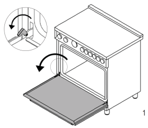
INSTALLING THE LEGS
Bertazzoni ranges must be used only with the legs properly installed.Four height-adjustable legs are supplied with the range in the polystyrene container situated over the appliance.Before installing the legs, position the appliance near its final location as the legs are not suitable for moving the appliance over long distances.After unpacking the range, raise it enough to insert the legs in the appropriate receptacles situated on the lower part of the appliance. Lower the range gently to keep any undue strain from legs and mounting hardware. If possible use a pallet or lift jack instead of tilting the unit.Adjust leg height to the desired level by twisting the inside portion of the leg assembly until the proper height is reached. Check with a level that the cooktop is perfectly level.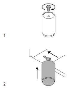

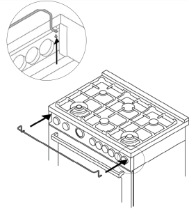
INSTALLING THE WORKTOP FRONTGUARD
To increase the clearance between the front edge of the worktop and the burners, it is possible to install a front guard for the worktop.To install the front guard,
- Locate the two fixing holes on the end of the front guard.
- Locate the two fixing holes on the bottom facet of the worktop
- Fix the front guard with it’s two screws
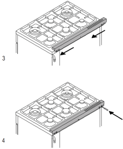
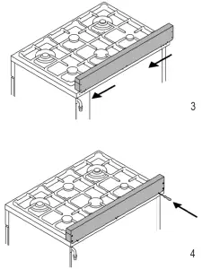
INSTALLING THE ISLAND TRIM
The island trim must be installed prior to operation of the appliance for appropriate ventilation of the oven compartment. The island trim is only placed on the cooktop, remove all tape and packaging before installing it.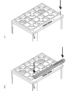
INSTALLING BACKGUARD (OPTIONAL)
The backguard must be installed prior to operation of the appliance for appropriate ventilation of the oven compartment. The backguard is an optional contact you dealer for buying it.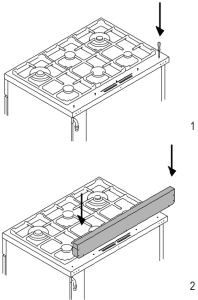
INSTALLING THE ANTI/TIP DEVICES
ANTI-TIP BRACKETS
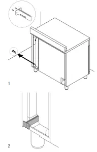
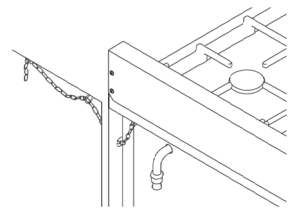
The anti-tip bracket shipped with the range must be properly secured to the rear wall as shown in the picture below.The height of the bracket from the floor must be determined after the range legs have been adjusted to the desired height and after the range has been levelled.
- Measure the distance from the floor to the bottom of the anti-tip bracket receptacle on the back of the appliance.
- Position the anti-tip brackets on the wall at the desired height plus 1/8″ (0.32 cm). The brackets must be placed at 2″5/16 (6,0 cm) from the side of the range.
- Secure the brackets to the wall with appropriate hardware.
- Slide the range against the wall until the brackets are fully inserted into their receptacles on the back of the range.

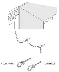
ANTI/TILT CHAIN
The anti-tilt chain shall be installed on right or left side alternatively according below instructions. The chain shall be hand pulled and fixed to open hook through closed ring. Disengage the chain prior to moving the appliance for service.
| Attention: Once servicing operation have been completed the anti-tilt devices ( brackets and chain) shall be re-engaged according above instruction/installations |
INSTALLATION CHECKLIST
A qualified installer should carry out the following checks:
☐ Range mounted on its legs☐ Island trim or Backguard attached according to instruction☐ Anti-tip device properly installed☐ Clearance to cabinet surfaces as manufacturer’s guideline
FINAL PREPARATION
- Before using the oven, remove any protective · wrap from the stainless steel.
- All stainless steel body parts should be wiped with hot, soapy water and with a liquid stainless steel cleanser.
- If buildup occurs, do not use steel wool, abrasive cloths, cleaners, or powders!
- If it is necessary to scrape stainless steel to remove encrusted materials, soak with hot, wet cloths to loosen the material, then use a wood or nylon scraper.
- Do not use a metal knife, spatula, or any other metal tool to scrape stainless steel! Scratches are almost impossible to remove.
- Before using the oven for food preparation, wash the cavity thoroughly with a warm soap and water solution to remove film residues and any dust or debris from installation, then rinse and wiped dry.
| Attention!When using the oven for the fi rst time it should be operated for 15-30 minutes at a temperature of about 500°F/260°C (main oven) or 440°F/227°C(auxiliary oven) without cooking anything inside in order to eliminate any moisture and odours from the internal insulation. |
BERTAZZONI SERVICE
Bertazzoni is committed to providing the best customer and product service. We have a dedicated team of trained professionals to answer your needs.If you own a Bertazzoni appliance and need service in the US or Canada please use the following contact information:
e-mail: [email protected]
Telephone – Monday through Friday,7.30am to 7.30pm EST (except US public holidays).
 report this ad
US 866-905-0010WESTERN CANADA 866-905-0010 (BC,AB,SK,MB)EASTERN CANADA 800-561-7265 (ON,QC,NL,NB,NS,PE)

References
[xyz-ips snippet=”download-snippet”]