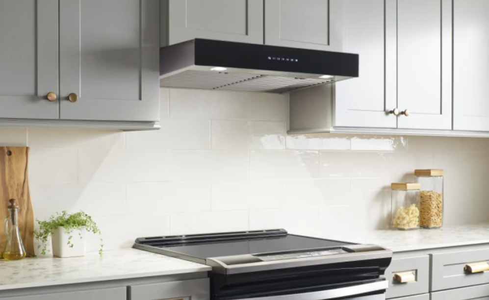
Best UCB3I Series
WARNINGTO REDUCE THE RISK OF FIRE, ELECTRIC SHOCK OR INJURY TO PERSONS, OBSERVE THE FOLLOWING:
- Use this unit only in the manner intended by the manufacturer. If you have questions, contact the manufacturer at the address or telephone number listed in the warranty.
- Before servicing or cleaning unit, switch power off at service panel and lock service disconnecting means to prevent power from being switched on accidentally. When the service disconnecting means cannot be locked, securely fasten a prominent warning device, such as a tag, to the service panel.
- Installation work and electrical wiring must be done by qualified personnel in accordance with all applicable codes and standards, including fire-rated construction codes and standards.
- Sufficient air is needed for proper combustion and exhausting of gases through the flue (chimney) of fuel burning equipment to prevent backdrafting. Follow the heating equipment manufacturer’s guidelines and safety standards such as those published by the National Fire Protection Association (NFPA) and the American Society for Heating, Refrigeration and Air Conditioning Engineers (ASHRAE) and the local code authorities.
- When cutting or drilling into wall or ceiling, do not damage electrical wiring and other hidden utilities.
- Ducted fans must always be vented d outdoors.
- To reduce the risk of fire or electric shock, do not use this unit with any additional solid-state speed control device.
- To reduce the risk of fire, use only metal ductwork.
- This unit must be grounded.
- All tempered glass can experience spontaneous breakage. If broken, tempered glass falls out of it’s opening in interlocking clumps. Tempered glass can, on occasion, break into large shards rather than the classic tiny piece pattern.
- When applicable local regulations comprise more restrictive installation and/or certification requirements, the aforementioned requirements prevail on those of this document and the installer agrees to conform to these at his own expense.
TO REDUCE THE RISK OF A RANGE TOP GREASE FIRE:
- Never leave surface units unattended at high settings. Boilovers cause smoking and greasy spillovers that may ignite. Heat oils slowly on low or medium settings.
- Always turn hood ON when cooking at high heat or when flambeing food (i.e.: Crêpes Suzette, Cherries Jubilee, Peppercorn Beef Flambé).
- Clean ventilating fans frequently. Grease should not be allowed to accumulate on fan, filters or in exhaust ducts.
- Use proper pan size. Always use cookware appropriate for the size of the surface element.
WARNINGTO REDUCE THE RISK OF INJURY TO PERSONS IN THE EVENT OF A RANGE TOP GREASE FIRE, OBSERVE THE FOLLOWING*:
- SMOTHER FLAMES with a close-fitting lid, cookie sheet or metal tray, then turn off the burner. BE CAREFUL TO PREVENT BURNS. IF THE FLAMES DO NOT GO OUT IMMEDIATELY, EVACUATE AND CALL THE FIRE DEPARTMENT.
- NEVER PICK UP A FLAMING PAN — You may be burned.
- DO NOT USE WATER, including wet dishcloths or towels — This could cause a violent steam explosion.
- Use an extinguisher ONLY if:
- You own a Class ABC extinguisher and you know how to operate it.
- The fire is small and contained in the area where it started.
- The fire department has been called.
- You can fight the fire with your back to an exit.
* Based on “Kitchen Fire Safety Tips” published by NFPA.
CAUTION
- For indoor use only.
- For general ventilating use only. Do not use to exhaust hazardous or explosive materials and vapors.
- To avoid motor bearing damage and noisy and/or unbalanced impellers, keep drywall spray, construction dust, etc. off power unit.
- Your hood motor has a thermal overload which will automatically shut off the motors if it overheats. The motors will restart when cooled down. If the motor(s) continues to shut off and restart, have the hood serviced.
- The minimum hood distance above cooktop must not be less than 24″. A maximum of 30″ above cooktop is highly recommended for best capture of cooking impurities. For a gas range, the bottom of the hood MUST NOT BE LESS than 30” above cooktop.
- Two installers are recommended because of the large size and weight of this unit.
- To reduce the risk of fire and to properly exhaust air, be sure to duct air outside — Do not exhaust air into spaces within walls or ceiling or into attics, crawl space or garage.
- Because of the high exhausting capacity of this unit, you should make sure enough air is entering the house to replace exhausted air by opening a window close to or in the kitchen.
- Use with approved cord-connection kit only.
- Please read specification label on product for further information and requirements.
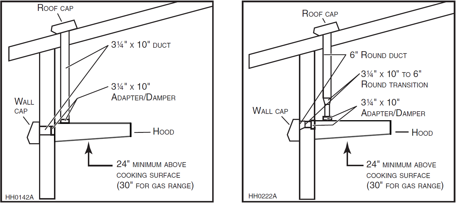
INSTALL DUCTWORK
Plan where and how the ductwork will be installed.The ducting from this fan to the outside of the building has a strong effect on the air flow, noise and energy use of the fan. Use the shortest, straightest duct routing possible for best performance, and avoid installing the fan with smaller ducts than recommended. Insulation around the ducts can reduce energy loss and inhibit mold growth. Fans installed with existing ducts may not achieve their rated airflow. Refer to the table at the bottom of this page to help you plan the most efficient installation.Install wall or roof cap; once done, ensure there is no leak in house insulation. Connect metal ductwork to cap and work back towards the hood location. If 6” round ducts are installed, use a 3¼” x 10” to 6” transition positioned, if possible, 18” away from the adapter/damper. Use 2” metal foil duct tape to seal the joints.We recommend to install the hood at a minimum distance of 24” from an electric range and of 30” from a gas range.Distances over 30” are at the installer and users discretion.
MAXIMUM DUCT LENGHTS RECOMMENDED TO ACHIEVE 80% EXHAUST EFFICIENCY
|
3 ¼” X 10” MAXIMUM DUCT LENGHT |
6” ROUND MAXIMUM DUCT LENGHT |
ROOF OR WALL CAP WITH DAMPER |
ELBOW(S)* (90° AND/OR 45°) |
|
60 FT. |
– |
1 |
0 |
|
50 FT. |
– |
1 |
1 |
|
40 FT. |
– |
1 |
2 |
|
– |
50 FT. |
1 |
0 |
|
– |
40 FT. |
1 |
1 |
|
– |
30 FT. |
1 |
2 |
* STANDARD ELBOWS WITH 1” INTERNAL RADIUS.
PREPARE THE INSTALLATION
NOTE: Before proceeding to the installation, check the contents of the box. If items are missing or damaged, contact the manufacturer. Make sure that the following items are included:
- Hood
- Accessories:
- 2 hybrid filters
- 3¼” x 10″ adapter/damper (located in one styrofoam end cap)
- Parts bag (located in one styrofoam end cap) including:1 wire clamp, 9 no. 8 x 1/2″ screws, 2 wire connectors and 3 no. 6 x 1/2″ standard screws
Parts sold separately:
- Ducts, elbows, wall or roof caps
- Transition 3¼” x 10” to 6” round (optional, for 6” round ducts installation only)
- Glass panel for UCB3I30SBN and UCB3I36SBN models
NOTES:
- During installation, protect countertop and/or cooktop.
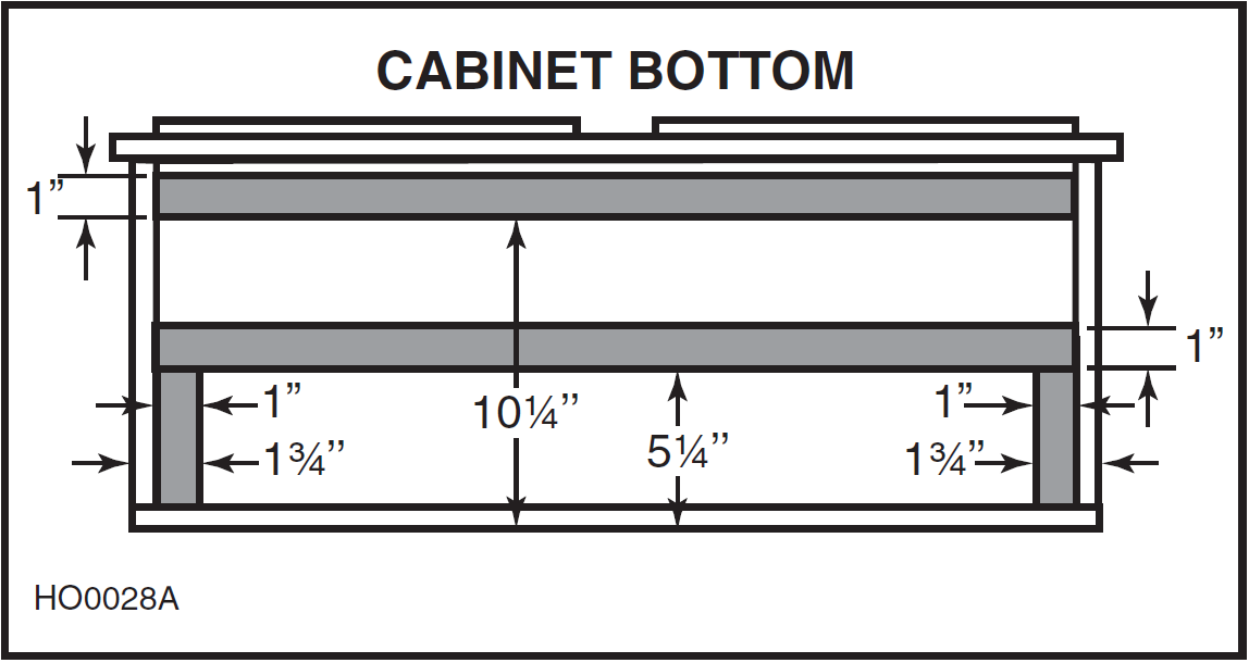
- If the bottom of the cabinet is recessed, attach four 1″ wide wood strips (not included), as shown at right, in order to properly attach the hood to the cabinet. The wood strips must be as thick as recess.
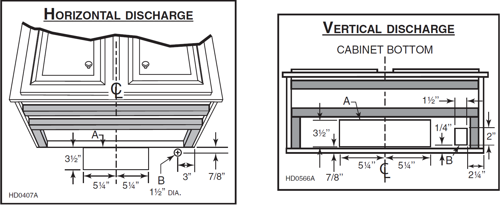
Cut-out the openings for duct (A) and power cable (B), in cabinet or wall, according to the direction of discharge chosen. See figures below.
PREPARE THE HOOD
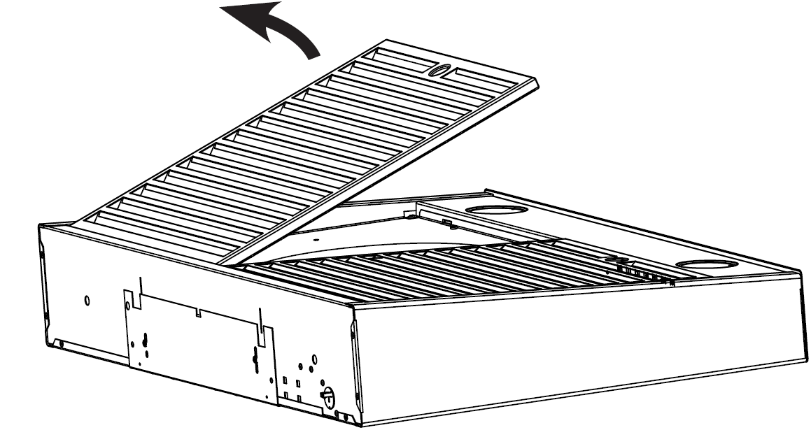
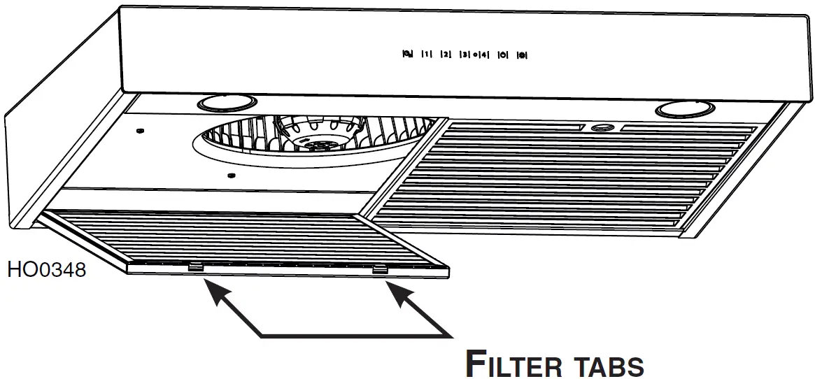
Lay the hood filters up on a table. Use a piece of cardboard to avoid damaging the table or the hood. Remove tape on filters. Lift filters by pushing them towards the back and flip them up, then set the filters aside.
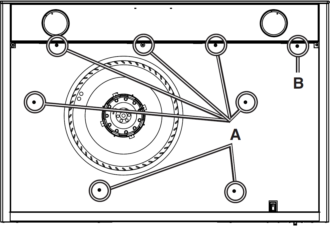
FOR 30” WIDE HOODS:Remove the 7 screws (A only) retaining the bottom panel, and set aside.FOR 36” WIDE HOODS:Remove the 8 screws (A and B) retaining the bottom panel and set aside.
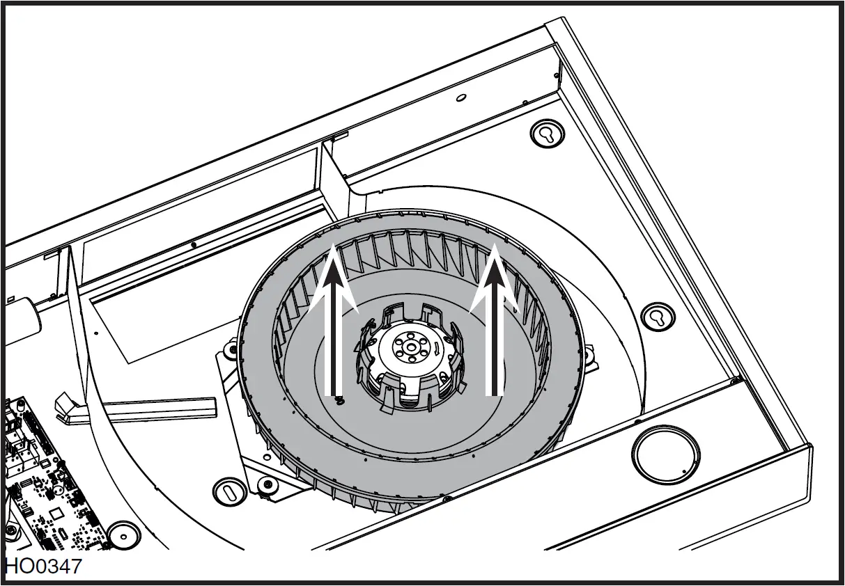
Using both hands, gently pull on the blower wheel to remove. Set blower wheel aside.
INSTALL GLASS PANEL (SBN MODELS ONLY)
The SBN hood models decorative glass panel is sold separately and has to be installed before completing the hood installation.
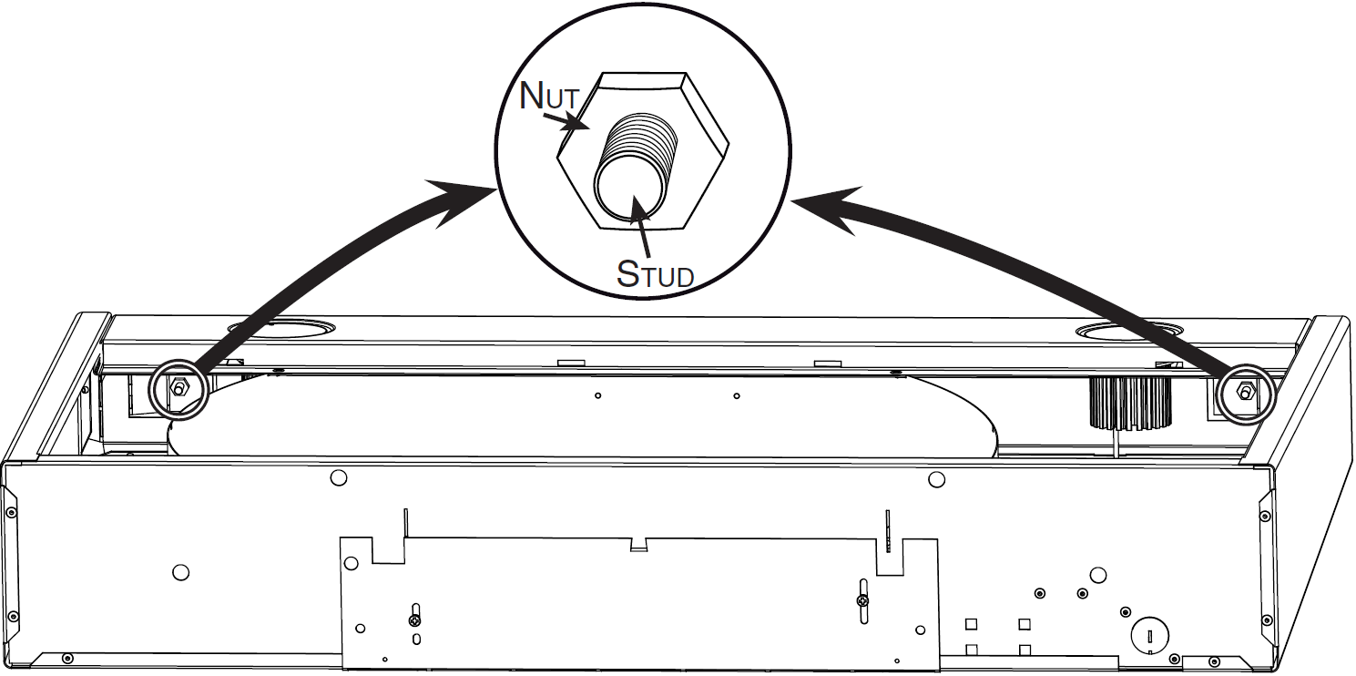
- Carefully remove glass panel from its packaging.Remove glass panel nuts (factory installed) from both studs and set aside.
- Insert glass panel studs in hood front holes.
- While holding glass panel, pre-tighten previously removed nuts by hand. Ensure glass panel is flush with top of hood and centered from side-to-side.Then, using a 3/8″ socket, tighten nuts completely.
INSTALL THE ADAPTER/DAMPER (ALL MODELS)
The wall duct must be roughed-in to properly interface with the hood. Before performing the installation, make sure the adapter fits easily in the duct. If this hood replaces an existing hood, please note that location of the air exhaust can vary from one manufacturer to another.
FOR HORIZONTAL DISCHARGE ONLY:
Turn the hood over and remove the metal shutoff plate from the back of the hood, by removing both retaining screws. Set screws aside.
Press the metal shutoff plate on a flat surface to completely flatten bent flange.
Using both screws previously removed, install the metal shutoff plate on top of the hood.
Fold down the foldable flange of the adapter/damper. This flange must be at 90° from the remaining flanges. See picture beside.
Using two no. 6 x 1/2’’ screws provided, secure the adapter/damper to the back of the hood. Remove tape from damper flap.Seal the adapter/damper to the hood using metal foil duct tape.
FOR VERTICAL DISCHARGE ONLY:Using two no. 6 x 1/2” screws provided, secure the adapter/damper to the top of the hood. Remove tape from damper flap.Seal the adapter/damper to the hood using metal foil duct tape.
INSTALL THE HOOD
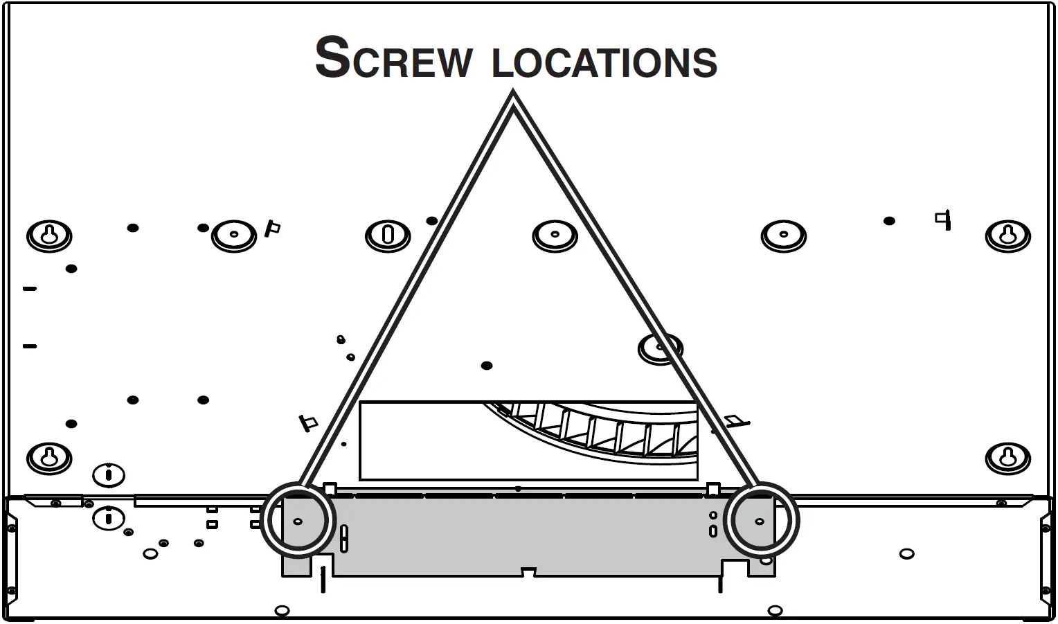
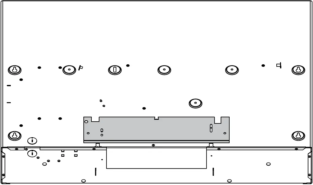
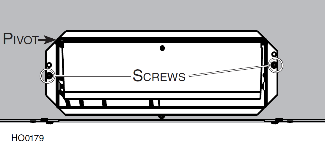
Run power cable to installation location. Position the hood in its intended location. Using a pen, mark the position of the screws (as shown at right). Remove the hood.
Install the first four no. 8 x 1/2″ screws, leaving a 1/8″ gap (do not install screws nos. 5, 6, 7, 8 and 9 yet).
Install the wire clamp and insert the power cable in the hood. Place the hood under the cabinet, slide it in position and tighten the wire clamp to secure the cable. Make sure the adapter/damper enters the duct opening. Tighten the first 4 screws completely, then add the last screws (screws nos. 5, 6, 7, 8 and 9) in the center holes. Make sure the damper flap opens freely.
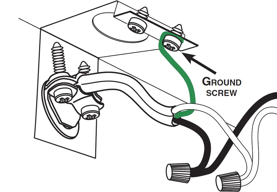
CONNECT WIRING
Connect cable to range hood wiring using included wire connectors.Connect BLACK to BLACK, WHITE to WHITE and GREEN or BARE WIRE to GREEN ground screw. DO NOT FORGET TO CONNECT THE GROUND.
REINSTALL BLOWER WHEEL AND BOTTOM PANEL
- Reinstall blower wheel: Using both hands, gently push on the blower wheel until secured.
- Insert bottom panel in the back of the hood.
- Secure bottom panel to the hood, using the 7 or 8 screws
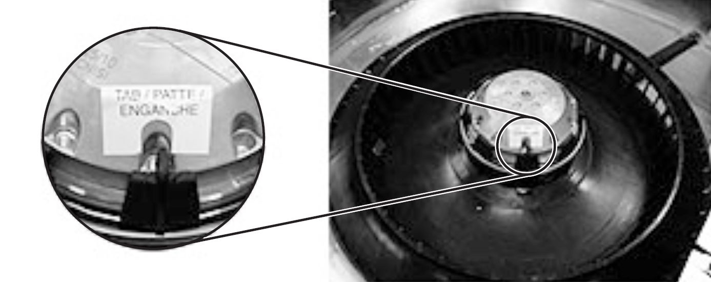
REINSTALL THE HYBRID FILTERS
CAUTIONRemove protective plastic film covering filters before reinstalling them.
Rest rear filters edge on filter springs in the range hood. Tilt up the filters into position. Make sure filter tabs are securely engaged in range hood front edge slots after installation.
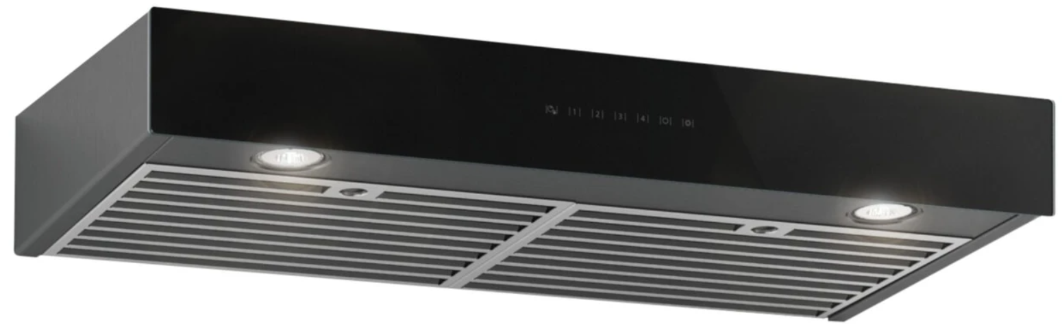
LED LIGHTING
The lighting of this hood is produced by two LED modules (included).
CARE
HYBRID FILTERS AND BOTTOM PANEL
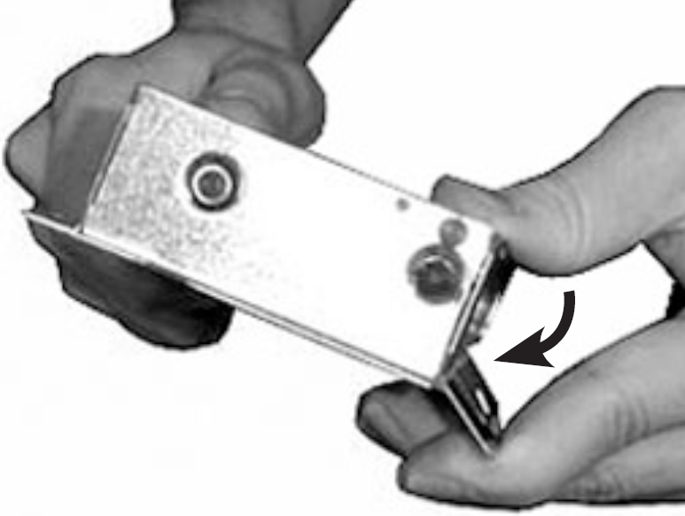
The hybrid filters and the bottom panel should be cleaned frequently. Use a warm detergent solution.Remove hybrid filters by pushing them towards the back of hood and rotating downward.Clean all-metal filters in the dishwasher using a non-phosphate detergent. Discoloration of the filters may occur if using phosphate detergents, or as a result of local water conditions — this will not affect filter performance. This discoloration is not covered by the warranty. To minimize or prevent discoloration, hand wash filters using a mild detergent.
STAINLESS STEEL
Do:
- Regularly wash with clean cloth or rag soaked with warm water and mild soap or liquid dish detergent.
- Always clean in the direction of original polish lines.
- Always rinse well with clear water (2 or 3 times) after cleaning. Wipe dry completely.
- You may also use a specialized household stainless steel cleaner.
Don’t:
- Use any steel or stainless steel wool or any other scrapers to remove stubborn dirt.
- Use any harsh or abrasive cleansers.
- Allow dirt to accumulate.
- Let plaster dust or any other construction residues reach the hood. During construction/renovation, cover the hood to make sure no dust sticks to stainless steel surfaces.
GLASS PANEL
Hot water with mild soap or glass cleaner is all that is usually needed.When using mild soap, rinse with clear water. Wipe dry with a clean, soft cloth to avoid water marks.
Avoid when choosing a detergent:
- Any cleaners that contain bleach. They will attack stainless steel.
- Any products containing chloride, fluoride, iodide, bromide. They will deteriorate surfaces rapidly.
- Any combustible products used for cleaning such as acetone, alcohol, ether, benzol, etc. They are highly explosive and should never be used close to a range.
OPERATION
Always turn your hood on before you begin cooking to establish an air flow in the kitchen. Let the blower run for a few minutes to clear the air after you turn off the range.
CAUTIONAfter a power failure or during the range hood power up, a 5-second booting sequence is executed. Wait for the control backlighting to turn off before use.
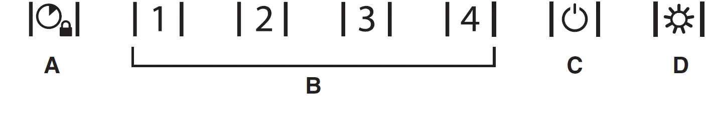
- DELAY BUTTON/CONTROL LOCK (DOUBLE FUNCTION BUTTON):
- When a blower speed is selected, press this button to activate the delay function. The delay button will light to its high intensity, then to its mid intensity to indicate this function is activated; the selected blower speed button will alternate every 2 seconds from its high intensity to its mid intensity. The blower will continue to operate for 5 minutes and will stop automatically. Selecting an other speed while the delay function is activated will not deactivate the function or reset the timer. To cancel the delay function, press the delay button once again, or press the selected speed button which will also turn the blower off.
- When blower is off, it is possible to lock the control interface in order to clean the glass panel.To lock the control interface: Press and hold the button for 2 seconds. The button will light to its high intensity and flash three times, it will then stay on its mid intensity to indicate that the control interface is locked.To unlock the control interface: Press and hold the button for 2 seconds. The button will light to its high intensity and flash 3 times, it will then fade out to its low intensity to indicate that the control interface is unlocked.
- SPEED SELECTION BUTTONS:Press the button corresponding to the desired blower speed (from 1 for low speed to 4 for high speed). The chosen speed button will light to its high intensity then fade to its mid intensity. To turn off the blower, press once more on the corresponding blower speed button; the button light will fade to its low intensityNOTE: When blower is off, pressing on blower speed 1 button will cause the blower to start on second speed for a very short lapse of time,and then resume on speed 1.NOTE: To decrease the maximum airflow from 600 CFM to 300 CFM, follow the instructions of the 300 CFM CRT kit (included with theunit, envelope no. 23894, or order SV23894 part).
- MASTER ON/OFF:When blower and lights are off, press this button to turn the hood on to the last memorized speed level. If there is no memorized speed level, speed will be set at level 1 and light intensity at 3. To turn off the blower and the light simultaneously, press this button once.HEAT SENTRY™: The hood is equipped with a HEAT SENTRY thermostat. If blower is ON at a lower speed setting and excessive heat isdetected above the cooking surface, it turns the blower up to third speed. When the temperature level drops to normal, the blower will return to its original setting.NOTE: When Heat Sentry is activated, the “DELAY OFF” function is inactivated.
- LIGHT BUTTON/BACKLIGHTING COLOR (DOUBLE FUNCTION BUTTON):
- This button allows three different lighting levels according to your needs. Press once for full intensity, twice for intensity level 2, and once more for nightlight. To turn off the lights, press once more.If desired, when the lights are on, press and maintain the light button for 1 second; lights will be turned off.NOTE: When only the lights are ON to any intensity and no interaction with the hood is detected for a 10-second period, the 7 buttons backlighting will fade to its low intensity, acting as a night light feature.
- When lights are off, pressing and holding this button for 1 second will switch the backlighting color from white to blue or from blue to white (default backlighting color is white) and memorize it. The button will flash three times to indicate that the color change has been made.NOTE: Due to the particular sensitivity of the control interface, keep the glass panel clean as dirt and condensation may cause erratic operation of the hood blower and/or lighting. If this situation occurs, wipe the glass panel and wait 90 seconds. Then, adjust the blower and/or lighting at your convenience.
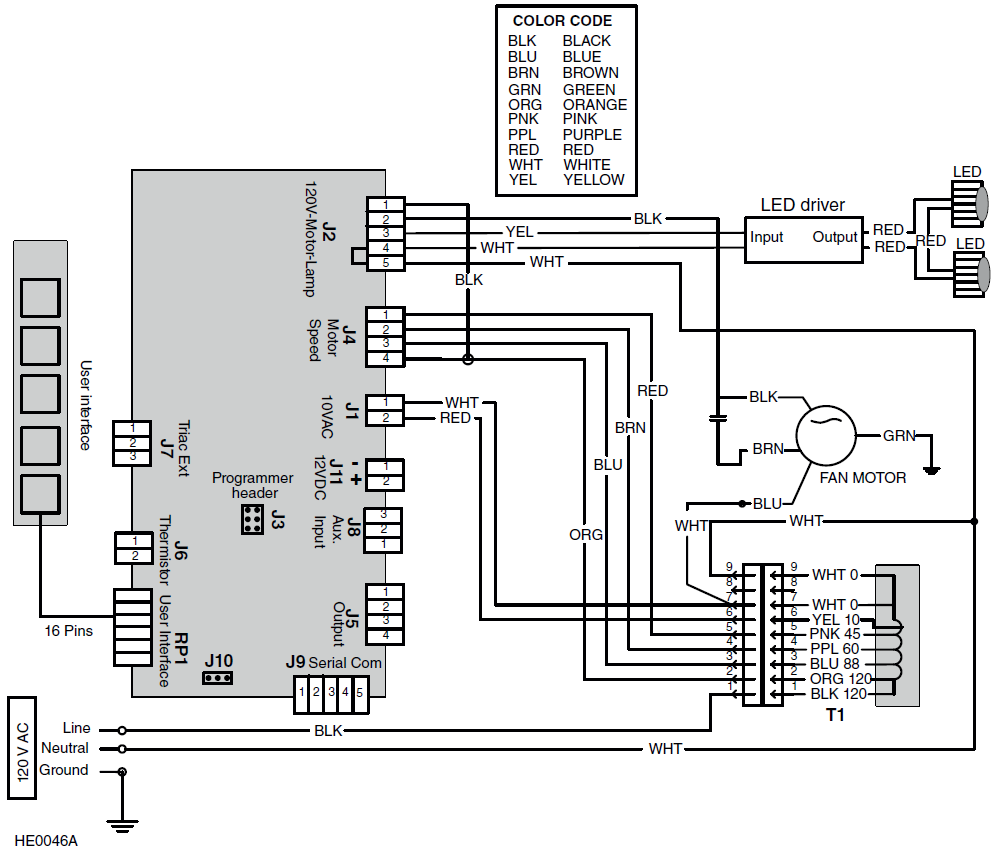
WIRING DIAGRAM
WARNINGRisk of electric shock. Electrical wiring must be done by qualified personnel in accordance with all applicable codes and standards. Before connecting wires, switch power off at service panel and lock service disconnecting means to prevent power from being switched on accidentally.
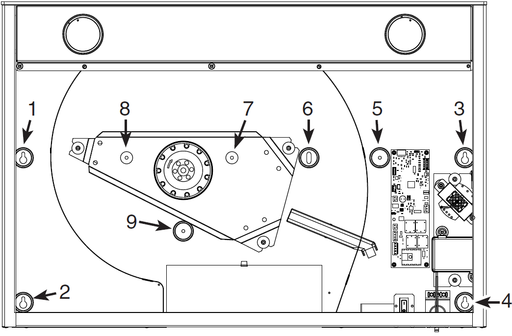
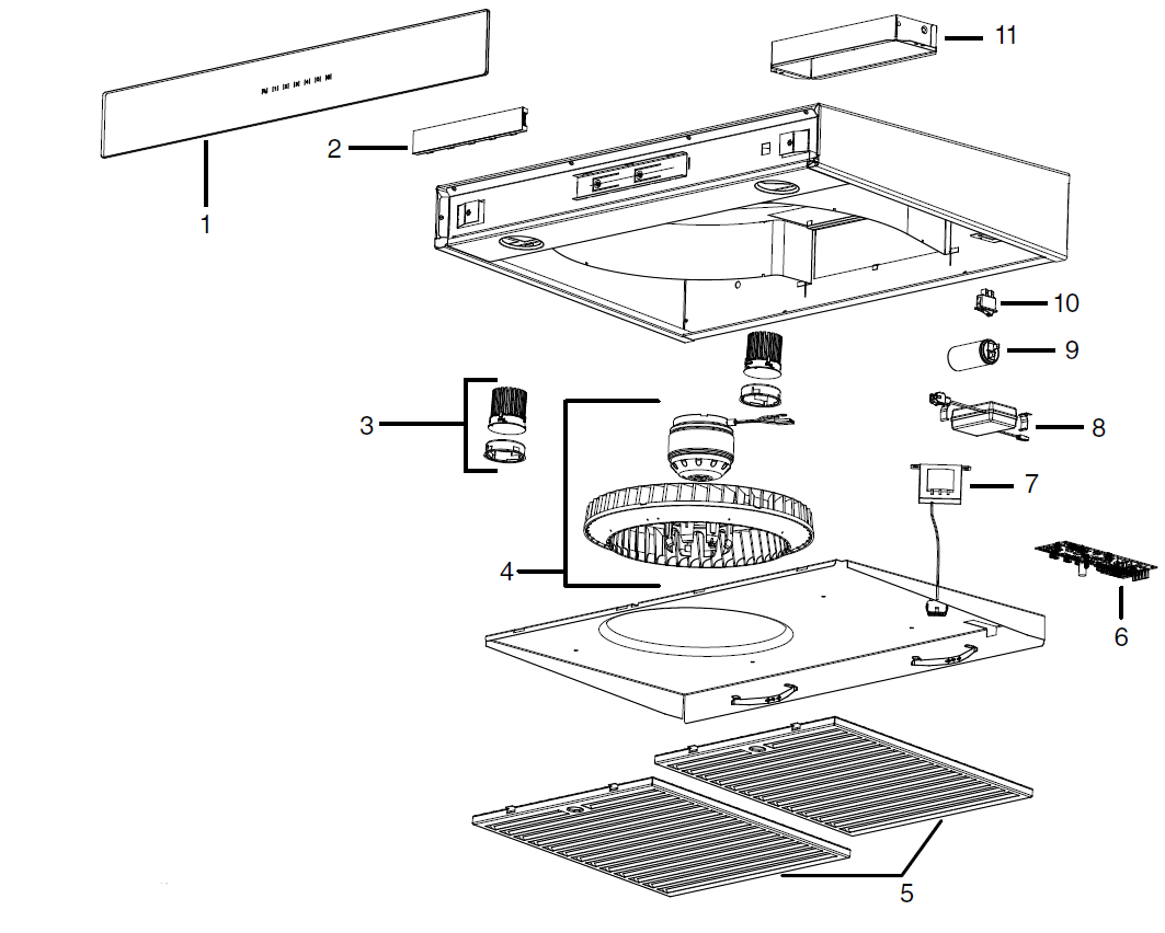
SERVICE PARTS
|
KEY NO. |
PART NO. |
DESCRIPTION |
WIDTHS |
|
|
30″ |
36″ |
|||
|
1 |
SV09953XX* |
GLASS PANEL 30” |
1 |
|
|
SV09954XX* |
GLASS PANEL 36” |
1 |
||
|
2 |
SV22427 |
ELECTRONIC CONTROL |
1 |
1 |
|
3 |
62612 |
LED MODULE |
2 |
2 |
|
4 |
SV01766E |
WHEEL AND MOTOR |
1 |
1 |
|
5 |
SV62053 |
HYBRID FILTER 15.875” X 14” x 0.5” |
2 |
2 |
|
6 |
SV21189 |
POWER UNIT |
1 |
1 |
|
7 |
SV07325 |
TRANSFORMER |
1 |
1 |
|
8 |
62248 |
LED DRIVER AND CONNECTION HARNESS |
1 |
1 |
|
9 |
SV02160 |
CAPACITOR |
1 |
1 |
|
10 |
SV08548 |
ROCKER SWITCH |
1 |
1 |
|
11 |
SV13296 |
ADAPTER/DAMPER |
1 |
1 |
|
** |
SV23894 |
CRT KIT 300 CFM (OPTIONAL) |
1 |
1 |
|
** |
SV05869 |
BEST LOGO |
1 |
1 |
|
** |
SV23864 |
INSTALLATION MANUAL |
1 |
1 |
|
** |
SV06751 |
HARDWARE BAG |
1 |
1 |
*PART NUMBER ACCORDING TO GLASS PANEL COLOR.PLEASE CONTACT CUSTOMER SERVICE OR VISIT WEB SITE.**ITEM NOT SHOWN.
REPLACEMENT PARTS AND REPAIRS
In order to ensure your unit remains in good working condition, you must use Broan-NuTone genuine replacement parts only. Broan-NuTone genuine replacement parts are specially designed for each unit and are manufactured to comply with all the applicable certification standards and maintain a high standard of safety. Any third party replacement part used may cause serious damage and drastically reduce the performance level of your unit, which will result in premature failing. Broan-NuTone recommends to contact a certified service depot for all replacement parts and repairs.
WARRANTY
FIVE-YEAR LIMITED WARRANTY FOR BEST® PRODUCTS
Warranty Period and Exclusions: Broan-NuTone, LLC (the “Company”) warrants to the consumer purchaser of its product (“you”) that the product (the “Product”) will be free from material defects in the materials or its workmanship for a period of five (5) years from the date of original purchase (or such longer period as may be required by applicable law) or a period of two (2) years from the date of service for any labor provided on the Product.The limited warranty period for any replacement parts provided by the Company and for any Products repaired or replaced under this limited warranty shall be the remainder of the original warranty period (or such longer period as may be required by applicable law).THIS WARRANTY DOES NOT EXTEND TO FLUORESCENT LAMP STARTERS, TUBES AND BULBS, FUSES, FILTERS, DUCTS, ROOF CAPS, WALL CAPS AND OTHER ACCESSORIES FOR DUCTING. This warranty does not cover (a) normal maintenance and service, (b) normal wear and tear, (c) any Products or parts which have been subject to misuse, abuse, abnormal usage, negligence, accident, improper or insufficient maintenance, storage or repair (other than repair by the Company), (d) damage caused by faulty installation, or installation or use contrary to recommendations or instructions, (f) damage caused by exposure to salt air, (g) damage in transit, (h) natural wear of finish, (i) Products in commercial or nonresidential use, (j) damage caused by fire, flood or other act of God, or (k) Products with altered, defaced or removed serial numbers. This warranty covers only Products sold to consumers in North America. This warranty supersedes all prior warranties and, subject to applicable law, is not transferable from the original consumer purchaser.No Other Warranties: This Limited Warranty contains the Company’s sole obligation and your sole remedy for defective Products. The foregoing warranties are exclusive and in lieu of any other warranties and conditions, express or implied. TO THE MAXIMUM EXTENT PERMITTED BY APPLICABLE LAW, THE COMPANY DISCLAIMS AND EXCLUDES ALL OTHER EXPRESS WARRANTIES AND CONDITIONS, AND DISCLAIMS AND EXCLUDES ALL WARRANTIES AND CONDITIONS IMPLIED BY LAW, INCLUDING WITHOUT LIMITATION THOSE OF MERCHANTABILITY AND FITNESS FOR A PARTICULAR PURPOSE. To the extent that applicable law prohibits the exclusion of implied warranties or conditions, the duration of any applicable implied warranty or condition is limited to the period specified for the express warranty above. Some jurisdictions (which may include the Province of Quebec or specific US states) do not allow limitations on how long an implied warranty lasts, so the above limitation may not apply to you. Any oral or written description of the Product is for the sole purpose of identifying it and shall not be construed as an express warranty.Whenever possible, each provision of this Limited Warranty shall be interpreted in such manner as to be effective and valid under applicable law, but if any provision is held to be prohibited or invalid, such provision shall be ineffective only to the extent of such prohibition or invalidity, without invalidating the remainder of such provision or the other remaining provisions of the Limited Warranty.Remedy: During the applicable limited warranty period, the Company will, at its option, provide replacement parts for, or repair or replace, without charge, any Product or part thereof, to the extent the Company finds it to be covered by and in breach of this limited warranty under normal use and service. The Company will ship the repaired or replaced Product or replacement parts to you at no charge. You are responsible for all costs for removal, reinstallation and shipping, insurance or other freight charges incurred in the shipment of the Product or part to the Company. If you must send the Product or part to the Company, as instructed by the Company, you must properly pack the Product or part—the Company is not responsible for damage in transit. The Company reserves the right to utilize reconditioned, refurbished, repaired or remanufactured Products or parts in the warranty repair or replacement process. Such Products and parts will be comparable in function and performance to an original Product or part and warranted for the remainder of the original warranty period (or such longer period as may be required by applicable law).Company reserves the right, in its sole discretion, to refund the money actually paid by you for the Product. If the Product or component is no longer available, replacement may be made with a similar product of equal or greater value, at Company’s sole discretion. This is your sole and exclusive remedy for breach of this limited warranty.Exclusion of Damages: THE COMPANY’S OBLIGATION TO PROVIDE REPLACEMENT PARTS, OR REPAIR OR REPLACE, AT THE COMPANY’S OPTION, SHALL BE YOUR SOLE AND EXCLUSIVE REMEDY UNDER THIS LIMITED WARRANTY AND THE COMPANY’S SOLE AND EXCLUSIVE OBLIGATION. THE COMPANY SHALL NOT BE LIABLE FOR INCIDENTAL, INDIRECT, CONSEQUENTIAL OR SPECIAL DAMAGES ARISING OUT OF OR IN CONNECTION WITH THE PRODUCT, ITS USE OR PERFORMANCE.Some jurisdictions do not allow the exclusion or limitation of incidental or consequential damages, so the above limitation or exclusion may not apply to you. This warranty gives you specific legal rights, and you may also have other rights, which vary from jurisdiction to jurisdiction. The disclaimers, exclusions, and limitations of liability under this warranty will not apply to the extent prohibited by applicable law.This warranty covers only replacement or repair of defective Products or parts thereof at the Company’s main facility and does not include the cost of field service travel and living expenses.Any assistance the Company provides to or procures for you outside the terms, limitations or exclusions of this limited warranty will not constitute a waiver of such terms, limitations or exclusions, nor will such assistance extend or revive the warranty. The Company will not reimburse you for any expenses incurred by you in repairing or replacing any defective Product, except for those incurred with the Company’s prior written permission.How to Obtain Warranty Service: To qualify for warranty service, you must (a) notify the Company at the address or telephone number stated below within seven (7) days of discovering the covered defect, (b) give the model number and part identification and (c) describe the nature of any defect in the Product or part. At the time of requesting warranty service, you must present evidence of the original purchase date. If you cannot provide a copy of the original written limited warranty, then the terms of the Company’s most current written limited warranty for your particular product will control.PRODUCT SPECIFICATIONSAll illustrations and specifications in this catalog are based on the latest product information available at time of production. Broan-NuTone, LLC and BEST® reserves the right to make changes at any time, without notice, in prices, colors, materials, equipment, specifications and models, place of manufacture and to discontinue models or equipment.BestBroan-NuTone, LLC- 926 W. State Street, Hartford, WI 53207 1-800-637-1453Best®, 550 Lemire Blvd., Drummondville, QC, Canada (1-866-737-7770) www.bestrangehoods.com
 report this ad
![]()
References
[xyz-ips snippet=”download-snippet”]