![]() Power for Today, Ideas for Tomorrow
Power for Today, Ideas for Tomorrow
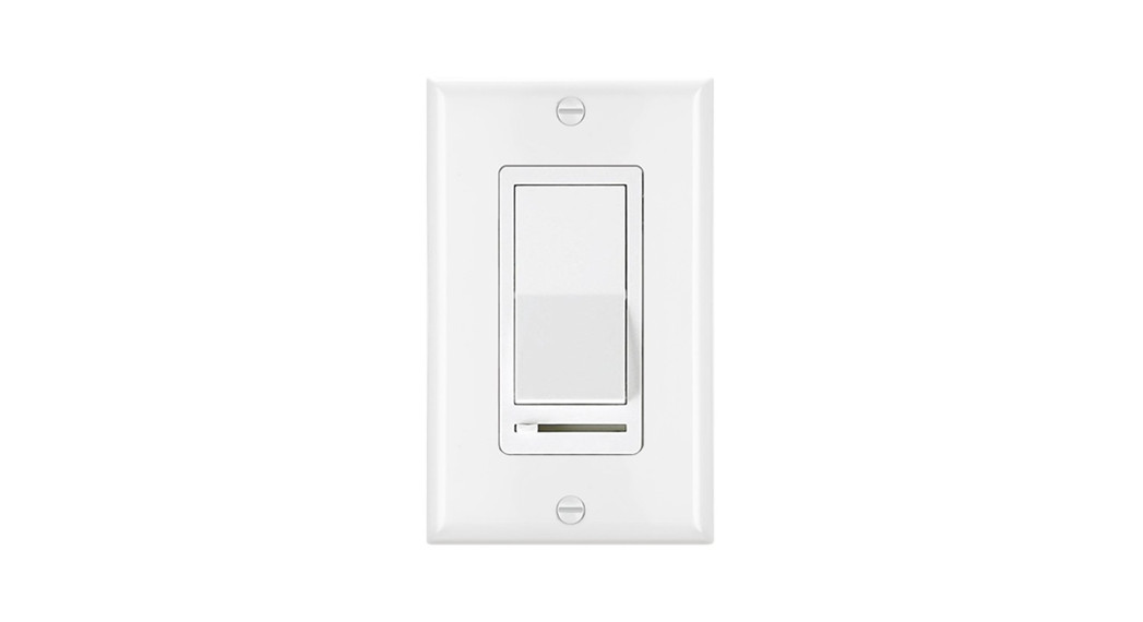
Dimmer Switch for LED/Compact Fluorescent/IncandescentSingle Pole (One Location) or 3-Way (Two Locations)LED/CFL 150W, Incandescent 600W 120VAC,60HZModel Number: USP3-LSO2USER MANUAL
WARNINGS AND CAUTIONS
- Use with compatible dimmable LED. CFL bulbs. Incandescent or 120V halogen fixtures only. To avoid overheating and possible damage to this device and other equipment, DO NOT install to control a receptacle, a motor-operated or a transformer-supplied appliance, or any other lighting sources than those specified.
- To be installed and/or used in accordance with appropriate electrical codes and regulations.
- Use only One dimmer in a 3-way circuit.
- When multiple bulbs are used with one dimmer. do not mix bulb types. All bulbs should be either LED. CFL or incandescent. Using the same make/model of each bulb will enhance dimmer performance.
- Use this device with copper or copper dad wire only.
- Clean dimmer with a soft damp cloth only. Do not use any chemical cleaners.
- If you are unsure about any part of these instructions, consult an electrician.
SPECIFICATIONS
Voltage………………… 120V, 60HzDimmable LED/CFL ………….Max. 150WIncandescent/Halogen ………………..Max. 600WSwitch Type ……………………Single Pole/3-WayOperation Temperature………………… 32°F (0°C)–104°F (40°C)Certifications ………………..UL/UL Listed
INSTALLATION
Multi-Gang Installations:When installing more than one control in the same wall box, it may be necessary to remove all the inner side sections prior to wiring. Using pliers, bend each needed side section up and down until it breaks off.Dimmer Capacity:600W unmodified500W if one side is removed400W if both sides are removed
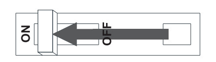
 STEP 1Turn OFF Power :
 STEP 2Identify Your Wiring Application (most common):NOTE: If the wiring in the wall box does not resemble any of these configurations, consult an electrician.
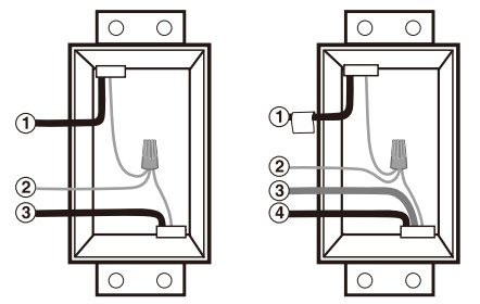
| Single-Pole | 3-Way |
| 1. Line (Hot)2. Ground3. Load 2. Ground | 1. Line or Load Common(See important instructions below)3. First Traveler4. Second Traveler |
IMPORTANT: For 3-way applications, note that one of the screw terminals from the old switch being removed will usually be a different color (Black) or labeled Common. Tag that wire with electrical tape and identify it as the common (Line or Load) in both the dimmer wall box and the standard 3-way switch wall box. The remaining two wires on the brass or lighter screw terminals of the old switch are the travelers.STEP 3Prepare Wires:
- Pull off the pre-cut insulation from the Dimmer wires.
- Make sure that the ends of the wires from the wall box are straight (cut if necessary).
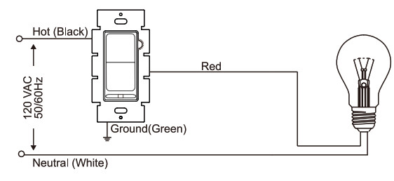
STEP 4ASingle Pole Wiring Application:

Connect wires as follows:Screw wire nuts clockwise making sure no bare conductors show below the wire connectors. Secure each connector with electrical tape.
- Green dimmer wire connects to Ground or bare copper wire.
- Black dimmer wire connects to Line Hotwire.
- Red dimmer wire without insulating label connects to Load wire.
- The remaining red dimmer wire should have an insulation label affixed. DO NOT REMOVE it in a single-pole application.
STEP 4B3 Way Wiring Application:
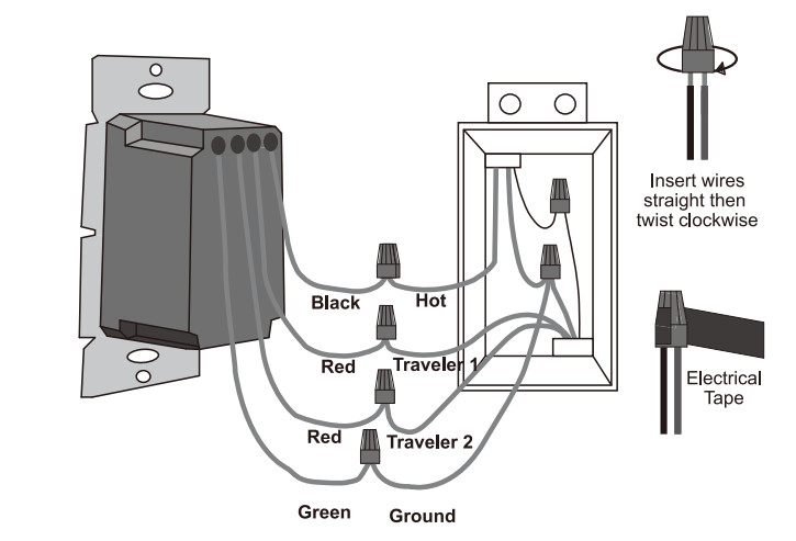 Connect wires as follows:Screw wire nuts on clockwise making sure no bare conductors show below the wire connectors. Secure each connector with electrical tape.
- Green dimmer wire connects to Ground or bare copper wire.
- Black dimmer wire connects to Line Hot or Load (Common) wire.
- Two Red dimmer wires connect to the two travelers.

STEP 5Dimmer Mounting:
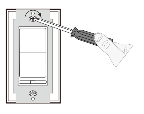 Installation may now be completed by carefully positioning all the wires to provide room in the wall box for the dimmer. Mount the dimmer into the box with supplied mounting screws.STEP 6Turn ON Power:
STEP 7Test Dimmer: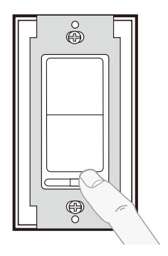
ON/OFF:Press rocker switch to ON/OFF position Lights will turn ON/OFFBRIGHTEN & DIM:Move the slider control lever Lights will BRIGHTEN or DIMIf the LEDs flicker, go to step 8 to adjust the dimmer range. If the LEDs work properly, install the wallplate and complete the installation.
STEP 8Adjust Dimming Range (optional):Adjust circuit dimming as follows:
- Turn on the switch and move the slide dimmer to the lowest (leftmost) setting.
- Rotate (Counter-Clockwise) the Sensitivity Dial all the way up.NOTE: If the dial stops in either direction, do not continue to turn it.
- Rotate (Clockwise) the Sensitivity Dial down slowly until the preferred lowest light level is achieved and the lights are not flickering.


Sensitivity Dial
- Rotate Counter-Clockwise More Bright
- Rotate Clockwise Less Bright
TROUBLESHOOTING
Symptom: – Bulbs turn off while being dimmed. – Bulbs turn on at high light level but do not turn on at a low light level, or take too long to turn on at the low end. – Bulbs flicker or flash when dimmed do a low light level. – Bulbs or dimmers are buzzing.Solution:
- Verify all bulbs are marked dimmable.
- Remove wallplate and locate sensitivity dial.
- Turn up the (counter-clockwise) sensitivity dial slowly until the symptom is no longer present.
WARRANTY
BESTTEN warrants to the original customer that this product is free of defects in materials and workmanship for one year from the purchase date. Within this period, simply contact BESTTEN CARE with proof of purchase and reason of claim We will replace the product for free.Any product which is subject to misuse or accidental damage is excluded from this warranty.[email protected] 1-800-358-6160 (Mon-Fri 9AM-5PM PST)For more products from BESTTEN. please visit our website www.ibestten.com.

[xyz-ips snippet=”download-snippet”]