BLACK BIRD 4K 4×4 HDBaseT Matrix with 3 Receivers User Guide
INTRODUCTION
This BlackbirdTM device can be controlled by a computer using an RS-232 serial connection and by issuing commands using RS-232 control software.
CONNECTION
This device includes a 3-pin to DB-9 RS-232 cable, which is used to connect your PC to the matrix to allow for matrix control. If your PC lacks a DB-9 serial port, you will need to use a USB to Serial adapter cable (available separately P/N 3726). Refer to the full User’s Manual for connection details.
SOFTWARE
This device does not include either a built-in control system or custom RS-232 control software. If you wish to control this device from your PC using an RS-232 connection, you will need to use a third party RS-232 control software package, such as CommWatch.exe, whose interface is depicted below.
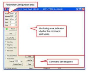
Set the communications parameters to the following: Baud Rate: 9600 Data Bits: 8 Stop Bits: 1 Parity Bits: None
| Baud Rate | 9600 |
| Data Bits | 8 |
| Stop Bits | 1 |
| Parity Bits | None |
RS-232 COMMANDS
The following guidelines apply to the RS-232 control commands.
- The brackets [ and ] in the commands are for clarity purposes to make the variable more obvious. Do not type these symbols when typing the commands.
- Other than the brackets, type in all commands exactly as they appear. They are case sensitive and require the trailing period (.) or semicolon (;) as part of the command.
- Disconnect all HDBaseTTM receivers from the matrix/transmitter prior to performing any of the upgrade commands.
|
System Commands |
||
| Command | Function | Feedback Example |
| /*Type; | Displays the model information. | XXXXX |
| /%Lock; | Locks the front panel buttons. | System Locked! |
| /%Unlock; | Unlocks the front panel buttons. | System Unlock! |
| /^Version; | Displays the firmware version. | VX.X.X |
| Demo. | Switches to “demo” mode, which automatically cycles through all the possible AV and IR connection combinations, with switching occurring every 2 seconds. | Demo Mode
AV: 01 -> 01 IR: 01 -> 01 AV: 01 -> 02 IR: 01 -> 02 … AV: 04 -> 04 IR: 04 – > 04 … |
|
Operation Commands |
||||||||||||||
| Command | Function | Feedback Example | ||||||||||||
| [X]All. | Directs input [X] to all output channels. (X=01~04) | X to All. | ||||||||||||
| All#. | Directs each input to its corresponding output (01 -> 01, 02 -> 02, etc.). | All Through. | ||||||||||||
| All$. | Switches all outputs off. | All Closed. | ||||||||||||
| [X]#. | Directs input [X] to output [X] (X=01~04) | X Through. | ||||||||||||
| [X]$. | Switches output [X] off. (X=01~04) | X Closed. | ||||||||||||
| [X]@. | Switches output [X] on. (X=01~04) | X Open. | ||||||||||||
| Switches all outputs on. | All Open. | |||||||||||||
| [X]V[Y]. | Directs the AV signal for input [X] to one or more outputs [Y]. Separate multiple outputs with a comma (,). (X/Y=01~04) | AV: X -> Y | ||||||||||||
| [X]B[Y]. | Directs both the AV and IR signals for input [X] to one or more outputs [Y]. Separate multiple outputs with a comma (,). (X/Y=01~04) | AV: X -> Y | ||||||||||||
| [X]R[Y]. | Directs the IR signal for input [X] to output [Y].
(X/Y=01~04) |
IR: X -> Y | ||||||||||||
| Status[X]. | Checks the I/O connection status of output [X]. (X/Y=01~04) | AV: Y -> X | ||||||||||||
| Status. | Displays each of the four AV and IR connections, one-by-one. | AV: 01 -> 01
… AV: 04-> 04 IR: 01 – > 01 … IR: 04 – > 04 |
||||||||||||
| Save[Y] | Saves the current connection settings to preset [Y].
(Y=0~9) |
Save to FY | ||||||||||||
| call[Y] | Loads the connection settings saved to preset [Y].
(Y=0~9) |
Recall From FY | ||||||||||||
| Clear[Y]. | Clears the connection settings saved to the preset [Y]. (Y=0~9) | Clear FY | ||||||||||||
| PWON. | Enables normal working mode. | PWON | ||||||||||||
| PWOFF PWOFF. PWOFF. | Enters standby mode and cuts off power to the HDBaseT™ receivers. | PWOFF | ||||||||||||
| STANDBY. | HDCP™ management command.
[Y] is for specifying input (I) or output (O). [X] is for the port number (1~5, where 5 represents all ports). [Z] is for the compliance status, where 1 sets the port to HDCP compliant and 0 sets the port to HDCP not compliant. |
/%[Y]/[X]:[Z] | ||||||||||||
| DigitAudioON[X]. | Enables HDMI® audio output for port [X].
(X=1~5, where 5 represents all ports) |
DigitAudio ON with [X] | ||||||||||||
| DigitAudioOFF[X]. | Disables HDMI audio output for port [X].
(X=1~5, where 5 represents all ports) |
DigitAudio OFF with [X] | ||||||||||||
| /+[Y]/[X]:[Z]. | Sets the communication parameters between the PC and one or more of the HDBaseT™ receivers. (Y=1~5 or A~H, where 1~4 sends the command to the corresponding HDBaseT receiver, 5 sends the command to all HDBaseT receivers. For A~H, the command is saved to the matrix/ transmitter and is not sent immediately to the corresponding HDBaseT receiver. For A~D, the saved command is sent to the corresponding HDBaseT receiver when a PWON command is sent and for E~H, the saved command is sent when a PWOFF command is sent.) (X is the baud rate, where 1=2400, 2=4800, 3=9600, 4=19200, 5=38400, 6=57600, and 7=115200)
(Z is for the data, up to 48 bytes) |
[Z]
|
||||||||||||
| EDIDH[X]B[Y]. | Sends the EDID® data from the display connected to output [X] to the source device connected to input [Y]. If EDID data is available and the audio portion supports audio types other than PCM, it forces it to set to PCM mode only. If EDID data is not available, the EDID is set to the default value.
(X/Y=1~4) |
EDIDH[X]B[Y] | ||||||||||||
| EDIDG[X]. | Gets the EDID® data from output [X] and displays the output port number. (X=1~4) | Hexadecimal EDID data and carriage return character. | ||||||||||||
| EDIDMInit. | Sets the EDID data for each input to the default value. | EDIDMInit | ||||||||||||
| EDIDM[X]B[Y]. | Sends the EDID data from output [X] to input [Y]. If EDID data is not available, it sets input [Y] to the default EDID value.
(X/Y=1~4) |
EDIDM[X]B[Y] | ||||||||||||
| EDIDUpgrade[X]. | Upgrades the EDID for input [X]. When the matrix/transmitter receives the command, it prompts you to send the EDID file (.bin file). The operation will be cancelled after 10 seconds if no file is sent. Note that all HDBaseT™ receivers must be disconnected prior to sending this command. (X=1~5, where 5 represents all inputs | Please send the EDID file | ||||||||||||
| EDID/[X]/[Y]. | Y EDID Settings 1 1080p 2D 2-channel audio 2 1080p 3D 2-channel audio 3 1080p 2D multichannel audio 4 1080p 3D multichannel audio 5 2D 2-channel audio
|
EDID/[X]/[Y] | ||||||||||||
| UpgradeIntEDID[X]. | Upgrades one of the 5 EDID® values on the embedded EDID table. When the matrix/transmitter receives the command, it prompts you to send the EDID file (.bin file). The operation will be cancelled after 10 seconds if no file is sent. Note that all HDBaseT™ receivers must be disconnected prior to sending this command. (X=1~5)
|
Please send the EDID file | ||||||||||||
| GetIntEDID[X]. | Returns the EDID data value from the embedded EDID table. (X=1~5) | |||||||||||||
| GetInPortEDID[X] | Returns the EDID data value for input [X]. (X=1~4)
|
|||||||||||||
| %0801. | Enables auto HDCP™ management and activates carrier native mode | %0801 | ||||||||||||
| %0900. | Switches to carrier native mode. | Carrier native | ||||||||||||
| %0901. | Switches to force carrier mode | Force carrier | ||||||||||||
| %0911 | Resets the matrix/transmitter to the factory default values | Factory Default | ||||||||||||
| %9951. | Displays the command sent by port 1 when a PWON command is sent. | Port 1:data when PWON | ||||||||||||
| %9952. | Displays the command sent by port 2 when a PWON command is sent. | Port 2:data when PWON | ||||||||||||
| %9953 | Displays the command sent by port 3 when a PWON command is sent. | Port 3:data when PWON | ||||||||||||
| %9954. | Displays the command sent by port 4 when a PWON command is sent. | Port 4:data when PWON | ||||||||||||
| %9955. | Displays the command sent by port 1 when a PWOFF command is sent. | Port 1:data when PWOFF | ||||||||||||
| %9956 | Displays the command sent by port 2 when a PWOFF command is sent | Port 2:data when PWOFF | ||||||||||||
| %9957. | Displays the command sent by port 3 when a PWOFF command is sent. | Port 3:data when PWOFF | ||||||||||||
| %9958 | Displays the command sent by port 4 when a PWOFF command is sent. | Port 4:data when PWOFF | ||||||||||||
| %9961. | Displays the system locking status | System Locked / Unlock! | ||||||||||||
| %9962. | Displays the power status. | STANDBY / PWON / PWOFF | ||||||||||||
| %9963. | Displays the IP address | IP:192.168.0.178 (default) | ||||||||||||
| %9971 | Displays the connection status for all inputs. (#=Y or N) | In 01 02 03 04 Connect # # # #
|
||||||||||||
| %9972 | Displays the connection status for all outputs. (#=Y or N) | Out 01 02 03 04 Connect # # # # | ||||||||||||
| %9973 | Displays the HDCP™ status of the inputs. (#=Y or N) | In 1 2 3 4 HDCP # # # ## | ||||||||||||
| 9974 | Displays the HDCP status of the outputs. (#=Y or N) | Out 1 2 3 4 HDCP # # # # | ||||||||||||
| &9975. | Displays the I/O connection status. | Out 01 02 03 04 In 01 02 03 04 | ||||||||||||
| %9976. | Displays the output resolution. | Out 1 1920×1080 Out 2 1920×1080 Out 3 1920×1080 Out 4 1920×1080 | ||||||||||||
| %9977. | Displays the status of digital audio for each output channel. (#=Y or N) | Out 1 2 3 4 Audio # # # # | ||||||||||||
| %9978 | Displays the HDCP compliance status of the inputs. (#=Y or N) | In 01 02 03 04 HDCPEN # # # # | ||||||||||||
| I-Lock[X]. | Locks channel [X]. (X=1~4) | Channel[X] Lock! | ||||||||||||
| I-Unlock[X] | Unlocks channel [X]. (X=1~4) | Channel[X] Unlock! | ||||||||||||
| A-Lock | Locks all channels. | All Channel Lock!
|
||||||||||||
| A-Unlock. | Unlocks all channels. | All Channel Unlock! | ||||||||||||
| Lock-Sta. | Displays the lock status of all channels. | Channel 1 -> Lock! Channel 2 -> Lock! … Channel 2 -> Unlock! .. |
References
[xyz-ips snippet=”download-snippet”]