
Compact Active Underseat Subwoofer
 ACTIVE SUBWOOFER XLf 8A1 061 610 800 001www.blaupunkt.comXLf 8A
Introduction
Please read these operating instructions before using the equipment for the rst time. We provide a manufacturer’s warranty for products bought within the European Union. For devices purchased outside the European Union, the warranty terms issued by our respective responsible domestic agency are valid. The warranty terms can be found at www.blaupunkt.com.
Safety Notes
Please observe the following safety notes during the installation and connection.
- Disconnect the negative terminal of the battery! Observe the safety notes of the vehicle manufacturer.
- When you drill holes, ensure that you do not damage any vehicle components.
- If the positive and negative cable are extended, ensure that the cross section is not less than 2.5 mm2.
- Incorrect installation can result in malfunction of the electronic vehicle systems or your car audio system.
Installation and connection instructions
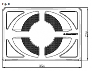
With respect to accident safety, the XLf 8A must be secured in a professional way. When selecting the installation location, select a dry location that offers sufficient air circulation for cooling the ampli er. The XLf 8A must not be installed on rear shelves, rear seats or other locations that are open to the front. The installation location must be suitable to accept the accompanying mounting hardware and provide a rm support (see page 4 / Fig. 1). The ampli er power cable must be tted with a fuse no more than 30 cm from the battery to protect the vehicle battery in case of a short circuit.The fuse of the ampli er protects only the ampli er, not the vehicle battery.
Connection (see page 5 / Fig. 2)
- 10 A fuse
- Preampli er inputs
- Power-on indicator (Protect/ Power)
- Input sensitivity
- Upper cut-off frequency
- Phase position
- Connector cable
- Right loudspeaker input
- Left loudspeaker input
- – Earth / Ground
- + Battery
Voltage supply
- We recommend a minimum cross section of 2.5 mm2.
- Route commercially available positive cables to the battery and connect via fuse holder.
- Use cable glands for holes with sharp edges.
- Securely fasten commercially available negative cables to a noise-free earth point (chassis screw, chassis metal) (not to the negative terminal of the battery).
- Scrape the contact surfaces of the ground point until they are bright and grease with graphite grease.
Connection 11 is connected to the positive terminal of the battery & connection 10 to negative vehicle ground. The control of the XLf 8A should ideally be a two-channel control either via the pre-ampli er outputs or the loudspeaker outputs of the car sound system. A control solely via the right or left channel is also possible since the low-frequency portion of the music is generally identical on both channels.
Integrated fuse
The fuse integrated in the amplifier protects the output stage and the entire electrical system in case of a malfunction. If a replacement fuse is used, never bridge fuses or replace them with a type with higher current rating.
Audio inputs
You can select between 2 different audio inputs;– Cinch (RCA)– Hi level (loudspeaker connections)Use only one of the audio inputs; otherwise, it may lead to audio interferences.
The preamplifier outputs are connected to the cinch (RCA) sockets 2 of the subwoofer box via a shielded sound cable. With control via the loudspeaker outputs, the input connections of pos. 8 / 9 are fed to the closest loudspeaker cables (front or rear) on the left and right. They are separated and connected to the input connections. The polarity of the + or connections must be observed. Bridge output stages (BTL) can also be connected directly without an additional adapter.
Switching on/off
A special feature of the XLf 8A is its automatic switch-on: The subwoofer automatically switches on if a music signal is received. If no music signal is received for more than 60 seconds, the XLf 8A automatically switches off.
VOL control
The VOL control 4 is used to adjust the input sensitivity of the power ampli er to the output voltage of your car sound system preampli er output. The adjustment range is from 0.1 V to 9.0 V. If a car sound system of a third party manufacturer is connected, the input sensitivity must be adjusted corresponding to the manufacturer data.
XLf 8A
A few important notes: By turning the control clockwise, the input sensitivity of the ampli er and, therefore, also the volume increases. However, this is not a volume control; no further amplifier output can be achieved in the end position, even if it may sound like that at the beginning. The system merely increases the volume faster if the volume control of the car sound system is turned up.
CROSSOVER frequency control
The CROSSOVER control 5 allows setting the desired exit frequency band in this base, 20 Hz – 80 Hz is the ideal frequency band.
Example:At a setting of 150 Hz, the ampli er has a frequency range of 20 Hz to 150 Hz. We suggest a setting of 80 Hz.
Settings
The following control setting is recommended as basic setting before putting the device into operation: Sensitivity (GAIN) Pos. 4 to minimum, PHASE Pos. 6 to 0°, x-over Pos. 5 to approx. 80 Hz. Switch on the device and select a musical piece with distinctive bass playback. Increase the volume of your car sound system to the desired volume level. Now slowly increase the VOL control 4 until you can hear a clear ampli cation of the bass level. Next, use the CROSSOVER control 5 to select a lter setting that provides a well-contoured bass. You may have to alternately optimise the sensitivity setting 4 and the lter setting 5 . The phase switch 6 must be set so that the bass is integrated into the acoustic pattern as best as possible and not recognisable as an individual source. Also check your settings of the XLf 8A with the bass control fully open and, if necessary, with activated loudness. An overloading of the subwoofer box by selecting an excessive ampli cation Pos. 4 results in a distorted playback and can damage the loudspeaker.
Power-on indicator (PRT/PWR)Green LED: Output stage on, regular operating status. Red LED: Output stage is electronically switched off due to an error.
Recycling and disposalPlease use the return and collection systems available to dispose of the product.Subject to changes!
Wiring diagramFig. 2:

Technical Data
| Amplifier | |
| Max Power | 320 W |
| RMS Power @ 14.4 V | 160 W |
| I max/min | 10 A / < 1.5 mA |
| Phase | 0° / 180° |
| Frequency response | 20 – 150 Hz |
| Low pass filter | 50 – 150 Hz |
| Gain (Cinch/RCA) | 0.1 V – 9.0 V |
| Gain (High Level Input) | 0.75 V – 7.5 V |
| Loudspeaker | |
| System |
Active Subwoofer Enclosure
|
| Cone size | 200 mm (8″) |
| Cone material | Aluminum Compound |
| Subwoofer box | |
| Size (WxHxD) | 340 x 225 x 91 mm |
| Weight | approx. 4.3 kg |
Blaupunkt India Private Limited 47, Atlanta Society, Nariman PointMumbai- 400 021. India. www.blaupunkt.com 1 061 610 800 001
References
[xyz-ips snippet=”download-snippet”]