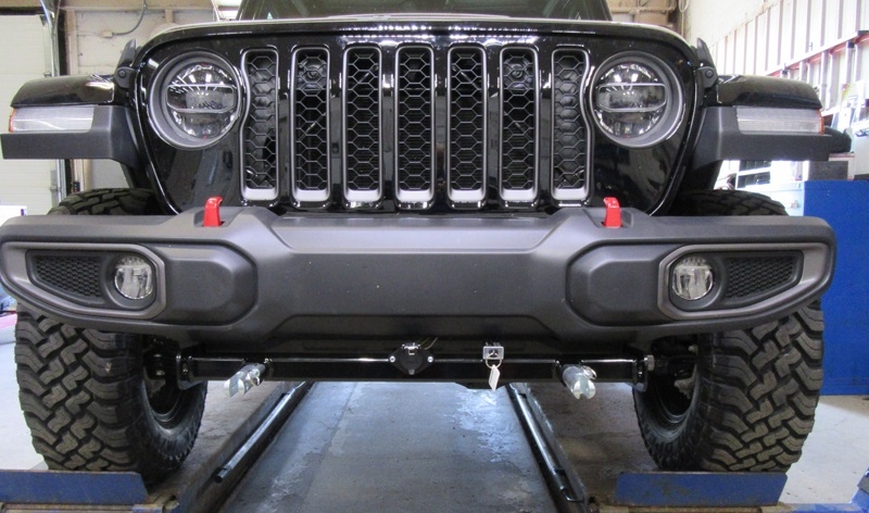
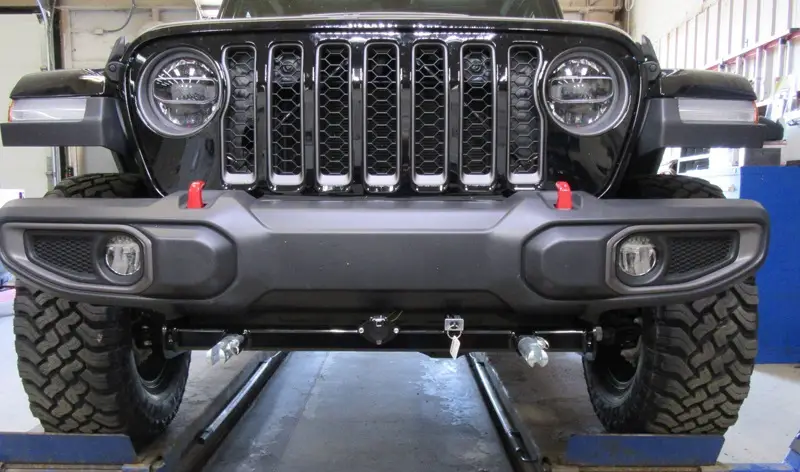
BLUE OX BX1142 Baseplate for 2020-21 Jeep Gladiator
Please visit www.blueox.com for the latest version of these installation instructions.Please read BOTH these Installation Instructions and the General Information sheet prior to installing or operating this equipment.
Attachment Tab Height: 17.25”Attachment Tab Width: 24”
- Blue Ox® towing products and accessories are intended to be installed by Blue Ox® Dealers who are familiar with our products and have the equipment and knowledge necessary to do “fit work”. If needed, Blue Ox® Dealers can be found at www.blueox.com or by contacting our Technical Service Department at (402) 385-3051.
- Many Blue Ox® baseplates are designed to use existing holes and hardware to mount the baseplate to the towed vehicle. Even though bolts are there, do not assume they are adequate for baseplate mounting. Always use the hardware supplied in the hardware kit and existing hardware as specified in the installation instructions.
Bolt Torque SpecificationsTorque in Foot-Pounds for Inch Bolts
| Bolt Size | Grade 5 | Grade 8 |
| 1/4” | 10 | 14 |
| 5/16” | 19 | 29 |
| 3/8” | 33 | 47 |
| 7/16” | 54 | 78 |
| 1/2” | 78 | 119 |
| 5/8” | 154 | 230 |
| 3/4” | 257 | 380 |
Bolt Torque SpecificationsTorque in Foot-Pounds for Metric Bolts
| Bolt Size | Grade 8.8 | Grade 10.9 |
| 6MM | 6 | 8 |
| 8MM | 16 | 22 |
| 10MM | 31 | 40 |
| 12MM | 54 | 70 |
| 14MM | 89 | 117 |
| 16MM | 161 | 230 |
| 18MM | 222 | 318 |

Installation Instructions
Reference your vehicle owner’s manual for manufacturer’s towing specifications.
WARNING: Failure to read and follow these instructions could result in separation of the towed vehicle from the tow bar, causing property damage, loss of towed vehicle, personal injury or death.
Instruction Notes: The bumper is removed and reinstalled for the baseplate installation. Some drilling and trimming is required.Place all components that are removed on a flat, sturdy surface. All items will be reinstalled unless otherwise noted after the baseplate is installed.The dimensional variations between otherwise identical vehicles can be considerable. While the baseplate was designed for easy installation, it may be necessary to tailor the baseplate slightly to compensate for vehicle manufacturer’s tolerances.The BX8848 Tail Light Wiring Kit is recommended for this vehicle.
NOTICE
- Handling of some cosmetic parts when installing this product may require the use of protective covers, rags, specialty tools, etc. to prevent damage.
- When using power drills be aware of the dangers of torque and drill bit length.
- When using a reciprocating saw be aware of objects behind the cutting surface.
- Use a good quality paint to spray cut edges of frame to prevent rusting.
- Be sure that ALL electrical connections are plugged in and accessories are functioning properly before reinstalling the fascia.
- The baseplate is computer tested to your vehicle’s GVWR, exceeding this weight will void the manufacturer’s warranty.
- Be sure to use a sufficient amount of Loctite® Red on all bolt threads before tightening. Tighten all bolts according to the torque chart provided unless specified.
- Dealer or installer be certain the user receives these instruction sheets.
- If the baseplate is in an accident, it must be replaced. DO NOT use it again! An accident can cause unseen damage and using it again could result in more damage or serious injury. DO NOT use the baseplate if it is damaged or missing parts.
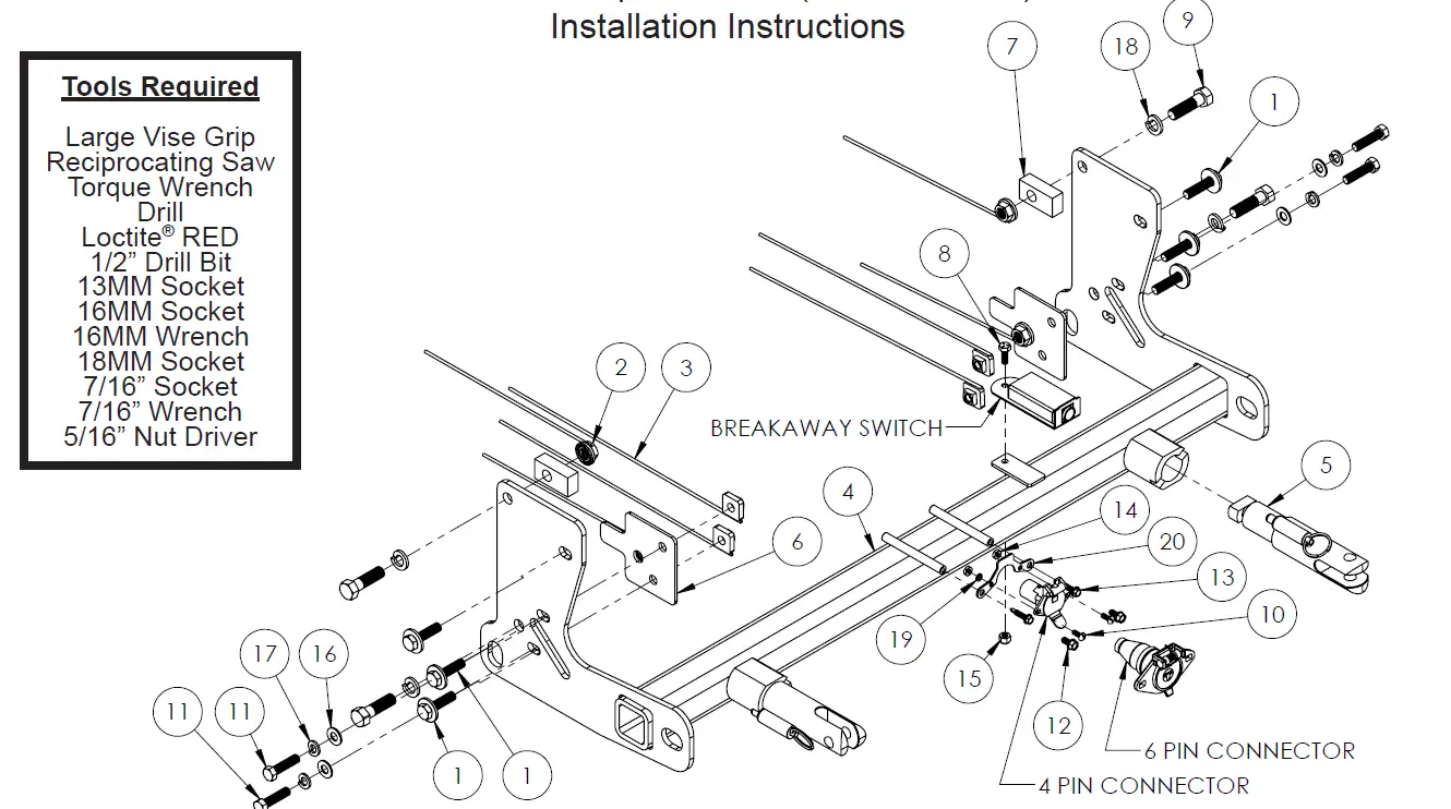
Item No. Part No. Description Qty.1……………………………..Existing………………………….. 10MM Bolt…………………………………………………………………..62……………………………..61-4029…………………………. 1/2”-13 Whiz Nut with 10” Wire………………………………………43……………………………..61-5208…………………………. 3/8”-16 Nut Plate with 14” Wire………………………………………44……………………………..61-8240…………………………. BX1142 Baseplate……………………………………………………….15……………………………..62-3468…………………………. Attachment Tab Assembly with Hole……………………………….26……………………………..101-10340……………………… Spacer Plate……………………………………………………………….27……………………………..102-7778……………………….. 5/8” x 1” x 2” Flat with Hole……………………………………………28……………………………..201-0050……………………….. 1/4”-20 x 3/4” Hex Head Bolt, Grade 5, ZP………………………19……………………………..201-0068……………………….. 1/2”-13 x 1-3/4” Hex Head Bolt, Grade 5, ZP…………………..410……………………………201-0192……………………….. #10-32 1/2” Round Slotted Head Screw………………………….211…………………………….201-0440……………………….. 3/8”-16 x 1-1/2” Hex Head Bolt, Grade 5, ZP…………………..412……………………………201-0553……………………….. 1/2”-20 x 1/2” Hex Washer Head Type F TCS, ZP……………213……………………………201-0979……………………….. #12-14 x 1” Self Drilling Screw, ZP…………………………………214……………………………202-0047……………………….. #10-32 Hex Nut……………………………………………………………215……………………………202-0102……………………….. 1/4”-20 Hex Nylon Nut, ZP…………………………………………….116……………………………203-0003……………………….. 3/8” Flat Washer, ZP…………………………………………………….417……………………………203-0010……………………….. 3/8” Lock Washer, ZP…………………………………………………..418……………………………203-0012……………………….. 1/2” Lock Washer, ZP…………………………………………………..419……………………………203-0054……………………….. #10 Lock Washer, ZP……………………………………………………220……………………………299-0685……………………….. Electrical Bracket, ZP…………………………………………………..121……………………………226-0049(not shown)………. Class III Safety Cables…………………………………………………222……………………………229-0512(not shown)………. 3/8” Quicklink, ZP………………………………………………………..223……………………………290-0437(not shown)………. Black Cap Plug Receiver………………………………………………2
Important:Use only genuine factory replacement parts on your baseplate. Do NOT substitute homemade or non-typical parts. If a bolt is lost or in need of replacement, for your safety and the preservation of your baseplate, be sure to use a replacement bolt of the same grade (In most cases it will be Grade 5, please reference the parts list above). Replacement parts may be ordered through your nearest Blue Ox® Dealer or Distributor. Failing to follow and/ or altering these installation instructions in either installation or required equipment will void the manufacturer’s warranty. Towing behind a non-motorized vehicle will void the warranty.
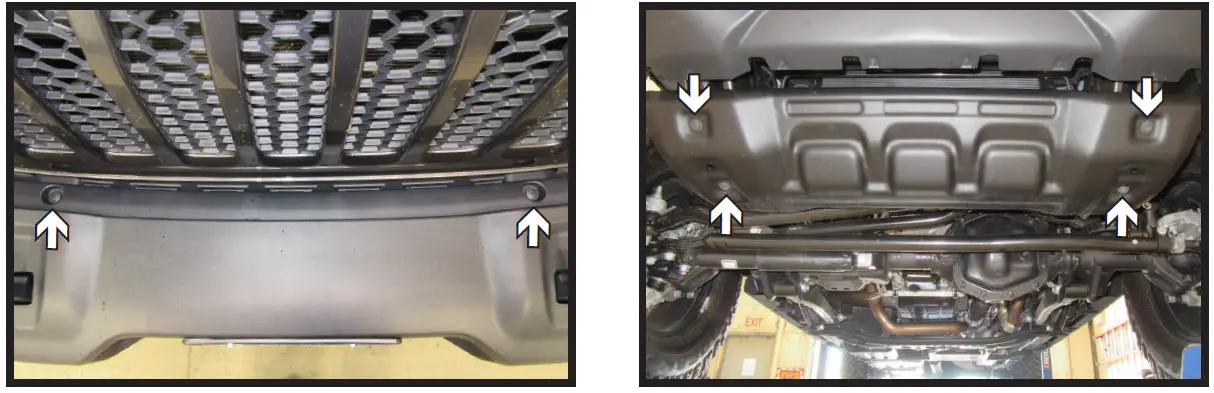
- Remove the two (2) push pins, one (1) on each side, from the plastic piece behind the bumper.
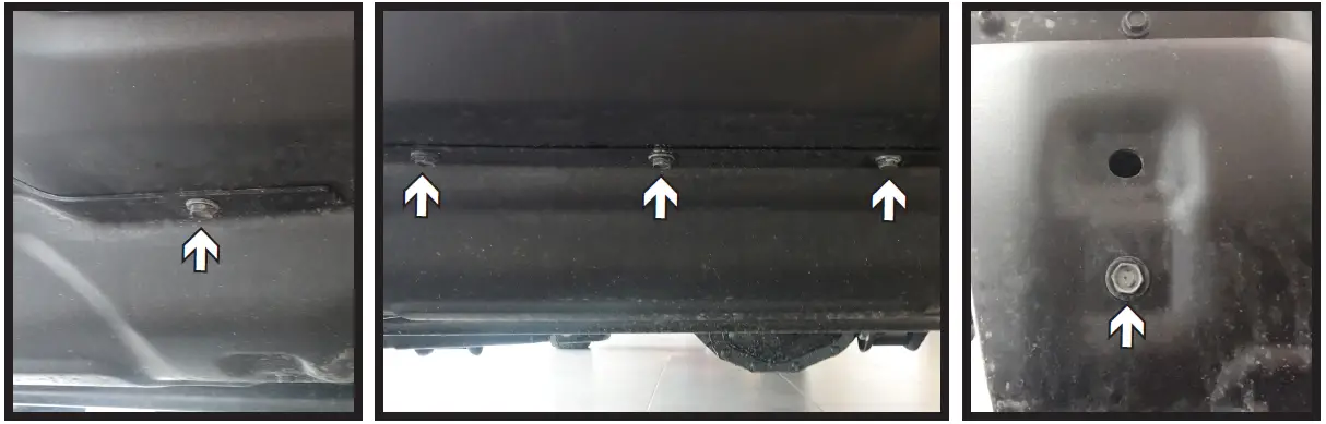
- Rubicon w/Plastic Bumper Models: Using a 13MM socket, remove the four (4) bolts from the belly pan. Remove belly pan and set aside to be reinstalled later.

- Rubicon w/Steel Bumper Models: Using an 13MM socket, remove the seven (7) bolts from the belly pan. There are five (5) bolts along the front edge (left and center) and two (2) in the back (right). Remove belly pan and set aside to be reinstalled later.
- Sport & Sport S Models: Remove the eight (8) push pins from the front edge of the belly pan, there are four (4) on each side (white). Then using an 8MM socket, remove the two (2) bolts (gray), one (1) on each side, from the belly pan. Remove belly pan and set aside to be reinstalled later.
- Overland Models: Remove the nine (9) push pins from the front edge of the belly pan, there is one (1) in each corner and seven (7) along the center (white). Then using an 8MM socket, remove the two (2) bolts (gray), one (1) on each side, from the belly pan. Remove belly pan and set aside to be reinstalled later.
- Rubicon w/Steel Bumper Models: Using an 13MM socket, remove the seven (7) bolts from the belly pan. There are five (5) bolts along the front edge (left and center) and two (2) in the back (right). Remove belly pan and set aside to be reinstalled later.
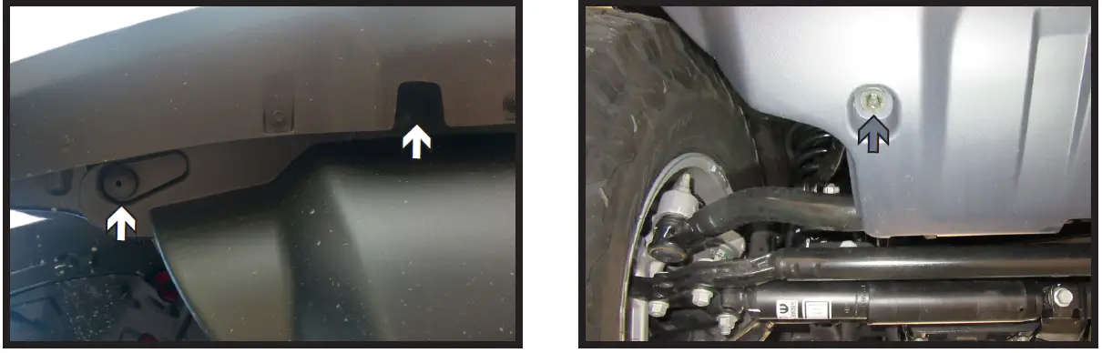
- Sport, Sport S, & Overland Models:Using a 16MM socket, remove the two (2) bolts from the skid plate. Push up on skid plate to release clips and remove. Set aside skid plate to be reinstalled later.
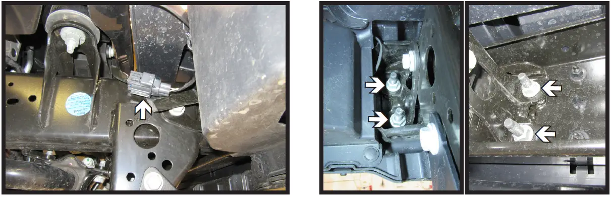
- Unplug the indicated electrical from the passenger side of the vehicle.
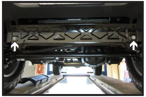
- Using an 18MM socket, remove the four (4) nuts holding the bumper to the frame.Do this on both sides of the vehicle. Remove the bumper and set aside to be reinstalled later.
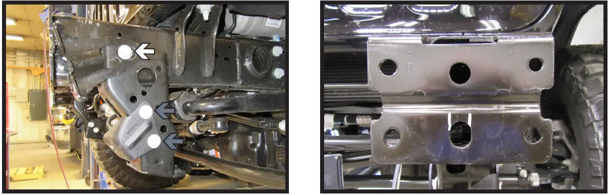
- All Models: Using a 16MM socket, remove the bolt holding the frame bracket (white).Rubicon w/Plastic Bumper Models:Using a 16MM socket, remove the two (2) bolts holding the belly pan bracket (gray).Remove brackets and set aside to be reinstalled later. Do this on both sides of the vehicle.
- Slot the middle bottom hole on the frame as indicated and bend inward to create an access hole. Do this on both sides of the vehicle.
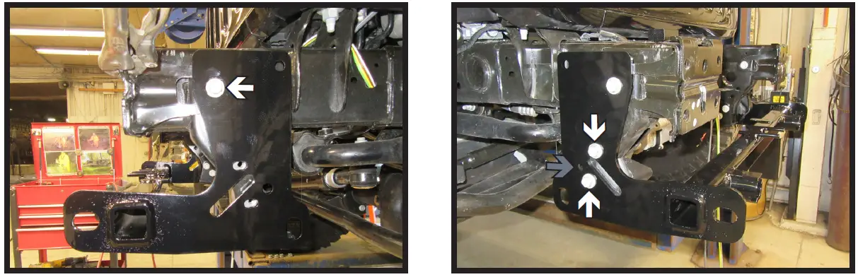
- Hold frame bracket in place with vice grip. Slide baseplate into position and start the top front 10MM existing bolt with hardware. Ensure that all holes line up and the baseplate is level, then snug down bolt. Do this on both sides of the vehicle.
- Rubicon w/Plastic Bumper Models:
- Place the belly pan bracket between the frame and the baseplate. Install the two (2) existing 10MM bolts (white). Then install the one (1) 1/2” bolt with hardware into the bottom back hole. May need to ream out the bottom back hole. Do this on both sides of the vehicle.
- All Other Models: Place the spacer plate between the frame and the baseplate. May need to use a pry bar to allow more room for the spacer plate to slide into place. Install the two (2) 3/8” bolts with hardware (white). Then install the one (1) 1/2” bolt with hardware into the bottom back hole. May need to ream out the bottom back hole. Do this on both sides of the vehicle.
- Place the belly pan bracket between the frame and the baseplate. Install the two (2) existing 10MM bolts (white). Then install the one (1) 1/2” bolt with hardware into the bottom back hole. May need to ream out the bottom back hole. Do this on both sides of the vehicle.
- Using a 1/2” drill bit, drill the top back hole using the baseplate as a guide. Install the one (1) 1/2” bolt with hardware. Do this on both sides of the vehicle.Use Loctite® Red on all bolt threads and tighten all bolts to the appropriate torque.
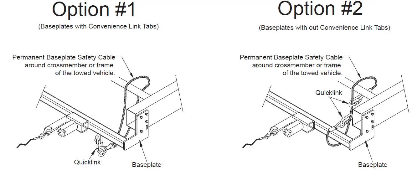
- Attach the permanent baseplate safety cables to the provided convenience link on the baseplate. The photo above shows the recommended installation of the cables to frame of vehicle. Additional options may interfere with suggested mounting; in this case, secure the cables to a solid piece of the frame as described in the General Information sheet. Be sure the safety cables do not rub against any hoses or moving parts. Do this on BOTH sides of the vehicle.
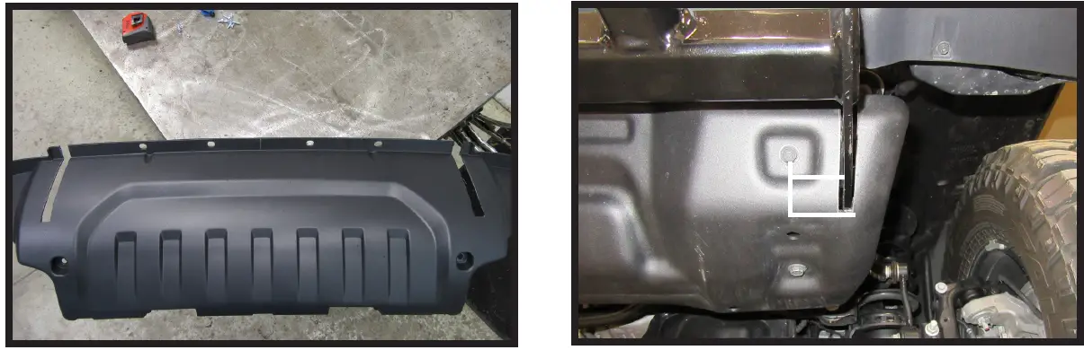
- Trim belly pan for baseplate clearance in one of two ways listed below then reinstall belly pan.Note: For Sport, Sport S, and Overland models the skid plate will need to be reinstalled before the belly pan.Option 1 – All Models: Hold belly pan as close to the original position, mark, and trim (left).Option 2 – Rubicon w/Plastic Bumper: Measure the distance from the center of the belly pan bracket hole to the inside of the baseplate and mark. Then measure from the center of the belly pan bracket hole to the outside of the baseplate and mark. May need to adjust the measurements slightly for clearance (left).
CUSTOMER SERVICE COMMITMENT
Blue Ox® is committed to providing you with exceptional customer care throughout your lifetime with our products. Our team is here to assist you with any questions you may have regarding the performance of your product. Simply call (402) 385-3051 and you can speak with our technical service team.
Additionally, please visit our website to see which rallies our Destination America team will be attending. For a nominal fee, our service technician will service your towing system to ensure it’s in proper working condition. Also, as a commitment to our customers, should you visit our factory, you can stay at our full service Blue Ox® campground at no charge along with enjoying a factory tour.Again, thank you for being our customer and for the confidence you have shown in the performance of our products. It is because of customers like you we enjoy the success we have today.
© 2016 Blue OxOne Mill Road, Industrial ParkPender, Nebraska 68047Phone: (402) 385-3051Fax: (402) 385-3360www.blueox.com
General Information
- Ensure that your product(s) are registered online at www.blueox.com. It is crucial to register your product(s) so that you may be alerted of product offerings, updates, upgrades, maintenance and safety bulletins, and/ or recalls.
- It is the owner’s responsibility to inspect all towing equipment for cracked welds, missing or worn parts and loose bolts before each towing trip. Be sure to use Loctite® Red on all bolts and tighten to the recommended specifications.
- It is the owner’s responsibility to hook up all towing equipment per manufacturer’s instructions/ recommendations.
- Remove the attachment tabs when not in use (if applicable).
Notice To Baseplate InstallerIt is YOUR responsibility to watch for:
- Oil cooler and air conditioner lines
- Electrical wires and hoses
- Missing parts or attaching points on the frameIf the baseplate is improperly installed and is against a wire or hose, it could cause fluid leaks or electrical shorts some time after the actual baseplate installation.
Permanent Baseplate Safety Cable InstallationPermanent baseplate safety cables are strongly recommended when towing a vehicle with a tow bar.The principle function of the permanent baseplate safety cables is to prevent the towed vehicle from breaking loose in the event the connection between the frame of the towed vehicle and the baseplate fails or becomes disconnected. The cables must be connected from the baseplate to the frame rail or cross member of the vehicle’s frame. The illustrations below show the possible arrangements recommended by Blue Ox®. Each permanent baseplate safety cable must have an adequate weightrating for the towing system. The weight rating of the two (2) cables together will not qualify.
Do not mount the permanent baseplate safety cables against wires, hoses or brake lines.
These permanent baseplate safety cables should remain installed as long as the baseplate is installed on the vehicle. Permanent baseplate safety cables are to be used in conjunction with, and NOT a replacement for legally required safety cables attaching the towed vehicle to the towing vehicle.
BLUE OX ORIGINAL PURCHASERS THREE YEAR LIMITED WARRANTY
Automatic Equipment Manufacturing Company (“Automatic”) warrants to the original (first) retail purchaser that this product, manufactured by Automatic, shall be free from defect in material and workmanship under normal use and service for a period of three years from the date of delivery.During said three-year period, Automatic will repair or replace any parts that have been returned by the original purchaser, to the factory, transportation prepaid, and in Automatic’s sole and absolute opinion found to be defective.
Limitations on Warranty Coverage:Coverage under this warranty will be valid only if the customer warranty card is returned by the original purchaser within 30 days of purchase.Coverage under this warranty will be effective only when a copy of the original invoice, showing date and place of purchase, accompanies any claim for warranty. This warranty is NON TRANSFERABLE.This limited warranty will not cover, in any way or form, any alleged damages caused by incorrect or improper installation, improper use, modification or neglect of product, failure to properly service and maintain, misuse, act of God, accident or failure of the user to follow guidelines contained in the instructional material provided by Automatic.This warranty does not cover normal wear and tear, paint or rust.
Warrantor assumes no responsibility to the owner for loss of use of product, loss of time, inconvenience or any other damage consequential or otherwise. Including, but not limited to mileage, expense of transporting of product, return shipping expense, mechanics travel time, telephone, road service, towing, and rental during repairs, travel, lodging, loss or damage to personal property or loss of earnings.
REPAIR OR REPLACEMENT AS SET FORTH IN THIS LIMITED WARRANTY IS THE SOLE EXCLUSIVE REMEDY OF THE PURCHASER. AUTOMATIC SHALL NOT BE LIABLE FOR ANY INCIDENTAL OR CONSEQUENTIAL DAMAGES FOR BREACH OF ANY EXPRESS OR IMPLIED WARRANTY ON THIS PRODUCT. EXCEPT TO THE EXTENT PROHIBITED BY APPLICABLE LAW, ANY IMPLIED WARRANTY OF MERCHANTABILITY OR FITNESS FOR A PARTICULAR PURPOSE ON THIS PRODUCT IS LIMITED IN LENGTH TO THE DURATION OF THIS WARRANTY.Please visit http://blueox.com/warranty/ to register your warranty
 report this ad
![]()
References
[xyz-ips snippet=”download-snippet”]