
![]()

REPLACEMENT PUMPSOWNER’S MANUALINSTALLATION, OPERATION & PARTS
NE4517 NE4518 NE4519 NE4513 NE4514NE4520 NE4521 NE4522 NE4515 NE4516 NEP4208
NE4523 NEP4268 NEP4269 NE4524 NEP4271
VER.0611
IMPORTANT - READ CAREFULLY
NOTE - To prevent potential injury and to avoid unnecessary service calls, read this manual carefully and completely.
SAVE THIS INSTRUCTION MANUAL
Use of unauthorized replacement parts voids warranty.
ATTENTION INSTALLER - THIS MANUAL CONTAINS IMPORTANT INFORMATION ABOUT THE INSTALLATION, OPERATION, AND SAFE USE OF THIS PUMP THAT MUST BE FURNISHED TO THE END USER OF THIS PRODUCT. FAILURE TO READ AND FOLLOW ALL INSTRUCTIONS COULD RESULT IN SERIOUS INJURY.
Safety Instructions
WARNING – To reduce risk of injury, do not permit children to use or climb on this product. Closely supervise children at all times. Components such as the filtration system, pumps, and heaters must be positioned to prevent children from using them as a means of access to the pool.
CAUTION – This pump is intended for use on permanently installed In Ground or Above Ground swimming pools and may also be used with hot tubs and spas if so marked. Do NOT use with storable pools. A permanently installed pool is constructed in or on the ground or in a building such that it cannot be readily disassembled for storage. A storable pool is constructed so that it is capable of being readily disassembled for storage and reassembled to its original integrity.Though this product is designed for outdoor use, it is strongly advised to protect the electrical components from the weather. Select a well-drained area, one that will not flood when it rains. It requires free circulation of air for cooling. Do not install in a damp or unventilated location. If installed within an outer enclosure or beneath the skirt of a hot tub or spa, adequate ventilation and free circulation of air must be provided to prevent overheating of the motor.
WARNING – Pool and spa components have a finite life. All components should be inspected frequently and replaced at least every ten years, or if found to be damaged, broken, cracked, missing, or not securely attached.
WARNING – Risk of Electric Shock.
Hazardous voltage. Can shock, burn, or cause death. To reduce the risk of electric shock, do NOT use an extension cord to connect unit to electric supply. Provide a properly located outlet. It is required that licensed electricians do all electrical wiring. All electrical wiring MUST be in conformance with applicable local and national codes and regulations. Before working on pump or motor, disconnect motor wiring.
WARNING - To reduce the risk of electric shock replace damaged cord immediately. Do NOT bury cord.
page 2
Locate cord to prevent abuse from lawn mowers, hedge trimmers and other equipment.
WARNING – Connect only to a grounding type receptacle protected by a Ground Fault Circuit Interrupter (GFCI).Contact a licensed electrician if you cannot verify that the receptacle is protected by a GFCI.
WARNING - Failure to bond pump to pool structure will increase risk for electrocution and could result in injury or death. To reduce the risk of electric shock, see installation instructions and consult a professional electrician on how to bond pump.Also, contact a licensed electrician for information on local electrical codes for bonding requirements. Use a solid copper conductor, size 8 or larger. Run a continuous wire from external bonding lug to reinforcing rod or mesh. Connect a No. 8 AWG (8.4 mm2) solid copper bonding wire to the pressure wire connector provided on the motor housing and to all metal parts of swimming pool, spa, or hot tub, and to all electrical equipment, metal piping (except gas piping), and conduit within 5 ft. (1.5m) of inside walls of swimming pool, spa, or hot tub. IMPORTANT – Reference NEC codes for all wiring standards including, but not limited to, grounding, bonding and other general wiring procedures. NOTE – The National Electrical Code (NEC) permits use of a cord with a maximum 3 ft. (1 m) length. If your pump is equipped with a cord complying with the NEC, the preceding four (4) hazards apply.
WARNING - Suction Entrapment Hazard.
Entrapment in suction outlets and/or suction outlet covers, which are damaged, broken, cracked, missing, or unsecured can cause severe injury and/or death due to the following entrapment hazards:Hair Entrapment- Hair can become entangled in suction outlet cover.Limb Entrapment- A limb inserted into an opening of a suction outlet sump or suction outlet cover that is damaged, broken, cracked, missing, or not securely attached can result in a limb becoming entrapped.Body Suction Entrapment- A pressure applied to a large portion of the body or limbs can result in an entrapment.Mechanical Entrapment- There is potential for jewelry, swimsuits, hair decorations, fingers, toes, or knuckles to be caught in an opening of a suction outlet cover resulting in mechanical entrapment.
WARNING – To Reduce the risk of Entrapment Hazards:
– When outlets are small enough to be blocked by a person, a minimum of two functioning suction outlets per pump must be installed. Suction outlets in the same plane (i.e. floor or wall), must be installed a minimum of three feet (3′) [0.91 meter] apart, as measured from near point to near point.– Dual suction fittings shall be placed in such locations and distances to avoid “dual blockage” by a user.– Dual suction fittings shall not be located on seating areas or on the backrest for such seating areas.– The maximum system flow rate shall not exceed the values shown in the “Pipe Sizing Chart” found at the bottom of page 5 of this manual.– Never use pool or spa if any suction outlet component is damaged, broken, cracked, missing, or not securely attached.– Replace damaged, broken, cracked, missing, or not securely attached suction outlet components immediately.
page 3
– In addition to two or more suction outlets per pump installed in accordance with latest IAF (formerly NSPI) standards and CPSC guidelines, follow all national, state, and local codes applicable.– Installation of a vacuum release or vent system, which relieves entrapping suction, is recommended.
WARNING - Hazardous Pressure.
Pool and spa water circulation systems operate under hazardous pressure during start-up, normal operation, and after pump shut-off. Stand clear of circulation system equipment during pump start-up. Failure to follow safety and operation instructions could result in violent separation of the pump housing and cover due to pressure in the system, which could cause property damage, severe personal injury, or death. Before servicing pool and spa water circulation system, all system and pump controls must be in off position and filter manual air relief valve if part of the filtration system must be in open position. Before starting system pump, all system valves must be set in a position to allow system water to return back to the pool. Do not change filter control valve position while system pump is running. Before starting system pump, fully open filter manual air relief valve. Do not close filter manual air relief valve until a steady stream of water (not air or air and water) is discharged. All suction and discharge valves MUST be OPEN when starting the circulation system.Failure to do so could result in severe personal injury and/or property damage.
WARNING - Separation Hazard.
Failure to follow safety and operation instructions could result in violent separation of pump components. Strainer cover must be properly secured to pump housing with strainer cover lock ring. Before servicing pool and spa circulation system, all system and pump controls must be in off position and filter manual air relief valve must be in open position. Do not operate pool and spa circulation system if a system component is not assembled properly, damaged, or missing. Do not operate pool and spa circulation system unless filter air relief valve body is in closed position. All suction and discharge valves MUST be OPEN when starting the circulation system. Failure to do so could result in severe personal injury and/or property damage.
WARNING – Never operate or test the circulation system at more than 40 PSI.
WARNING - Fire and burn hazard.
Motors operate at high temperatures and if they are not properly isolated from any flammable structures or foreign debris they can cause fires, which may cause severe personal injury or death. It is also necessary to allow the motor to cool for at least 20 minutes prior to maintenance to minimize the risk for burns.
WARNING – Failure to install according to defined instructions may result in severe personal injury or death.
page 4
Installation Instructions
WARNING - This product should be installed and serviced only by a qualified professional.
Pump LocationLocate pump as close to pool as practical and run suction lines as direct as possible to reduce friction loss. Suction lines should have continuous slope upward from lowest point in line. Joints must be tight (but not over-tightened). Suction line diameter must equal or be larger than the discharge line diameter.Though the pump is designed for outdoor use, it is strongly advised to protect the electrical components from the weather. Select a well-drained area, one that will not flood when it rains. Do NOT install pump in a damp or non-ventilated location. Keep motor clean. Pump motors require free circulation of air for cooling.
Pump MountingInstall pump on a firm, level base or pad to meet all local and national codes. Fasten pump to base or pad with screws or bolts to further reduce vibration and stress on pipe or hose joints. The base MUST be solid, level, rigid, and vibration free.
Pump mount must:Allow pump inlet height to be as close to water level as possible.Allow use of short, direct suction pipe (to reduce friction losses).Allow for gate valves in suction and discharge piping.Be protected from excess moisture and flooding.Allow adequate access for servicing pump and piping.
Pipe Sizing Chart
| MAXIMUM RECOMMENDED SYSTEM FLOW RATE BY PIPE SIZE | |||||
| Pipe Size
[mm] |
Flow rate
GPM[Liter/Min] |
Pipe Size
[mm] |
Flow rate
GPM[Liter/Min] |
Pipe Size
[mm] |
Flow rate
GPM[Liter/Min] |
| 1”
[32] |
20
[75] |
1 1/2”
[50] |
45
[170] |
2 1/2”
[75] |
110
[415] |
| 1 1/4”
[40] |
30
[110] |
2”
[63] |
80
[300] |
3”
[90] |
160
[600] |
NOTE – It is recommended that a minimum length of piping, equivalent to 10 pipe diameters, be used between the pump suction inlet and any plumbing fittings.
WARNING - Hazardous Pressure.
Pumps, filters, and other equipment/ components of a swimming pool filtration system operate under pressure. Incorrectly installed and/or improperly tested filtration equipment and/or components may fail resulting in injury and/or property damage.
PlumbingUse “Teflon” tape available at any plumbing or hardware store, to seal threaded connections on molded plastic components. All plastic fittings must be new or thoroughly cleaned before use. NOTE – Do NOT use Plumber’s Pipe Dope as it may cause cracking of the plastic components. When applying ” Teflon ” tape to plastic threads, wrap the entire threaded portion of the male fitting with one to two layers of tape. Wind the tape clockwise as you face the open end of the fitting, beginning at the end of the fitting. The pump suction and outlet ports have molded-in thread stops. Do NOT attempt to force hose connector fitting past this stop. It is only necessary to prevent leakage. Tighten fitting by hand and then use a tool to engage fitting an additional 1 ½ turns. Use care when using Teflon tape as friction is reduced considerably; Do NOT over-tighten fitting or you may cause damage. If leaks occur, remove fitting, clean off old Teflon tape, re-wrap with one to two additional layers of Teflon tape, and re-install fitting.
FittingsFittings restrict flow. For better efficiency, use the fewest possible fittings (but at least two suction outlets). Avoid fittings that could cause an air trap. Pool and spa fittings MUST conform to the International Association of Plumbing and Mechanical Officials (IAPMO) standards. Use a non-entrapping suction fitting in pool (multiple drains) or double suction (skimmer and main drain).
Electrical
WARNING – Ground and bond motor before connecting to electrical power supply. Failure to ground and bond pump motor can cause serious or fatal electrical shock hazard.
WARNING – Do NOT ground to a gas supply line.
WARNING - To avoid dangerous or fatal electrical shock, turn OFF power to motor before working on electrical connections.
WARNING – Ground Fault Circuit Interrupter (GFCI) tripping indicates electrical problem. If GFCI trips and won’t reset, consult electrician to inspect and repair electrical system.
WARNING - Fire Hazard.
Match supply voltage to motor nameplate voltage.Insure that the electrical supply available agrees with the motor’s voltage, phase, and cycle, and that the wire size is adequate for the H.P. (KW) rating and distance from the power source. NOTE – All electrical wiring MUST be performed by a licensed electrician, and MUST conform to local codes and NEC regulations. Use copper conductors only.
| Max Rate | Full Rate | 60Hz, 1PH | ||||
| HP | KW | HP | KW | Voltage | Amps | Wire Size |
| 1/2 | 0.37 | 208-230
115 |
10A
15A |
14AWG
14AWG |
||
| 1 | 0.75 | 3/4 | 0.55 | 208-230
115 |
10A
15A |
14AWG
14AWG |
| 1-1/2 | 1.10 | 1 | 0.75 | 208-230
115 |
15A
20A |
14AWG
12AWG |
| 2 | 1.55 | 1-1/2 | 1.10 | 208-230
115 |
15A
30A |
14AWG
10AWG |
| 2-1/2 | 1.87 | 2 | 1.55 | 208-230 | 20A | 12AWG |
| 3 | 2.20 | 2-1/2 | 1.87 | 208-230 | 20A | 12AWG |
page 6
VoltageVoltage at motor MUST NOT be more than 10% above or below motor name plate rated voltage, or motor may overheat, causing overload tripping and reduced component life. If voltage is less than 90% or more than 110% of rated voltage when motor is running at full load, consult Power Company.
Grounding and BondingInstall, ground, bond, and wire motor in accordance with local or national electrical code requirements. Permanently ground motor. Use green ground terminal provided under motor canopy or access place; use size and type wire required by code. Connect motor ground terminal to electrical service ground. Bond motor to pool structure. Bonding will connect all metal parts within and around the pool with a continuous wire. Bonding reduces the risk of a current passing between bonded metal objects, which could potentially cause electrical shock if grounded or shorted. Reference NEC codes for all wiring standards including, but not limited to, grounding, bonding and general wiring procedures.Use a solid copper conductor, size 8 or larger. Run wire from external bonding lug to reinforcing rod or mesh. Connect a No. 8 AWG (8.4 mm2) solid copper bonding wire to the pressure wire connector provided on the motor housing and to all metal parts of swimming pool, spa, or hot tub, and to all electrical equipment, metal piping (except gas piping), and conduit within 5 ft. (1.5 m) of inside walls of swimming pool, spa, or hot tub.
Wiring
WARNING - All wiring must be done by a licensed electrician.
Pump MUST be permanently connected to circuit. If other lights or appliances are also on the same circuit, be sure to add their amp loads before calculating wire and circuit breaker sizes. Use the load circuit breaker as the Master On-Off switch.Install a Ground Fault Circuit Interrupter (GFCI) in circuit; it will sense a short-circuit to ground and disconnect power before it becomes dangerous to pool users. For size of GFCI required and test procedures for GFCI, see manufacturer’s instructions. In case of a power outage, check GFCI for tripping, which will prevent normal pump operation. Reset if necessary.
NOTE – If you do not use conduit when wiring motor, be sure to seal wire opening on end of motor to prevent dirt, bugs, etc., from entering.
Start-Up & Operation
Prior to Start-UpNotice: If it is necessary to perform a pressure test, prior to initial use to ensure pump is functioning properly, then the following criteria should be maintained for this test:
- Have a professional perform this test.
- Ensure all pump and system components are sealed properly to prevent leaks.
- Remove any trapped air in the system by fully opening filter manual air relief valve until a steady stream of water is discharged.
- Allow no more than 40 psi (276 kPa) at a water temperature no higher than 100°F (38°C).
- Run pressure test for no longer than 24 hours. Immediately inspect all parts to verify they are intact and functioning properly.
page 7
Fill strainer housing with water to suction pipe level. NEVER OPERATE THE PUMP WITHOUT WATER. Water acts as a coolant and lubricant for the mechanical shaft seal.
WARNING – If pump is being pressure tested (40 PSI MAXIMUM), be sure pressure has been released, using the filter manual air relief valve, before removing strainer cover.
CAUTION – NEVER run pump dry. Running pump dry may damage seals, causing leakage, flooding, and voids warranty. Fill strainer housing with water before starting motor.
ATTENTION – Do NOT add chemicals to pool/spa system directly in front of pump suction. Adding undiluted chemicals may damage pump and voids warranty.
ATTENTION - Before removing strainer cover:
- STOP PUMP before proceeding.
- CLOSE VALVES in suction and outlet pipes.
- RELEASE ALL PRESSURE from pump and piping system using filter manual air relief valve. See filter owner’s manual for more detail.
Priming Pump
CAUTION – All suction and discharge valves MUST be OPEN, as well as filter air relief valve (if available) on filter, when starting the circulating pump system. Failure to do so could result in severe personal injury.Release all pressure from filter, pump, and piping system. See filter owner’s manual.If water source is higher than the pump, pump will prime itself when suction and outlet valves are opened. If water source is lower than the pump, unscrew and remove strainer cover; fill strainer housing with water.Clean and lubricate strainer cover O-ring with high quality O-ring lubricant each time it is removed. Inspect O-ring and re-install on strainer cover.Replace strainer cover on strainer housing; turn clockwise to tighten cover.
NOTE – Tighten strainer cover by hand only (no wrenches).
Turn on power and wait for pump to prime, which may take up to five (5) minutes. Priming time will depend on vertical length of suction lift and horizontal length of suction pipe. If pump does NOT prime within five minutes, stop motor and determine cause. Be sure all suction and discharge valves are open when pump is running. See Troubleshooting Guide.
ATTENTION - Wait five (5) seconds before re-starting pump. Failure to do so may cause reverse rotation of motor and consequent serious pump damage.Close filter manual air relief valve after pump is primed.
MaintenanceClean strainer basket regularly. Do NOT strike basket to clean. Inspect strainer cover gasket regularly and replace as necessary.
Pumps have self-lubricating motor bearings and shaft seals. No lubrication is necessary.Keep motor clean. Insure air vents are free from obstruction to avoid damage. Do NOT use water to hose off motor.Occasionally, shaft seals must be replaced, due to wear or damage. Replace with genuine seal assembly kit. See “Shaft Seal Change Instructions” in this manual.
Storage/Winterization
WARNING - Separation Hazard.
Do not purge the system with compressed air. Purging the system with compressed air can cause components to explode, with risk of severe injury or death to anyone nearby. Use only a low pressure (below 5 PSI), high volume blower when air purging the pump, filter, or piping.
ATTENTION - Allowing the pump to freeze will void the warranty.
ATTENTION – Use ONLY propylene glycol as antifreeze in your pool/spa system. Propylene glycol is nontoxic and will not damage plastic system components; other anti-freezes are highly toxic and may damage plastic components in the system.Drain all water from pump and piping when expecting freezing temperatures or when storing pump for a long time (see instructions below).Keep motor dry and covered during storage. To avoid condensation/corrosion problems, do NOT cover or wrap pump with plastic film or bags.
Storing Pump for Winterization
WARNING - To avoid dangerous or fatal electrical shock hazard, turn OFF power to motor before draining pump. Failure to disconnect power may result in serious personal injury or death.
- Drain water level below all inlets to the pool.
- Remove drain plugs from bottom of strainer body, and remove strainer cover from strainer housing.
- Disconnect pump from mounting pad, wiring system (after power has been turned OFF), and piping system.
- Once the pump is empty of water, re-install the strainer cover and drain plugs. Store pump in a dry area.
Shaft Seal Change Instructions
IMPORTANT SAFETY INSTRUCTIONS
When servicing electrical equipment, basic safety precautions should always be observed including the following. Failure to follow instructions may result in injury.
A. WARNING – To reduce risk of injury, do not permit children to use or sevice this product.
page 9
B. Disconnect all electrical power service to pump before beginning shaft seal replacement.C. Only qualified personnel should attempt rotary seal replacement. Contact your local authorized Dealer or service center if you have any questions.D. Exercise extreme care in handling both the rotating and the stationary sections of the two-part replacement seal. Foreign matter or improper handling will easily scratch the graphite and ceramic sealing surfaces.
Troubleshooting
Motor Will NOT Start Check For:Make sure the terminal board connections agree with the wiring diagram on motor data plate label. Be sure motor is wired for available field supply voltage (see pump operating label).
- Improper or loose wiring connections; open switches or relays; tripped circuit breakers, GFCI’s, or blown fuses.Solution: Check all connections, circuit breakers, and fuses. Reset tripped breakers or replace blown fuses.
- Manually check rotation of motor shaft for free movement and lack of obstruction.
- If you have a timer, be certain it is working properly. Bypass it if necessary.
Motor Shuts OFF Check For:1. Low voltage at motor or power drop (frequently caused by undersized wiring or extension cord use).Solution: Contact qualified professional to check that the wiring gauge is heavy enough.NOTE – Your pump motor is equipped with an “automatic thermal overload protector.” The motor will automatically shut off if power supply drops before heat damage can build up causing windings to burn out. The “thermal overload protector” will allow the motor to automatically restart once the motor has cooled. It will continue to shut off until the problem is corrected. Be sure to correct cause of overheating.
Motor Hums, But Does NOT Start Check For:1. Impeller jammed with debris.Solution: Have a qualified repair professional open the pump and remove the debris.
Pump Won’t Prime, Check For:1. Empty pump/strainer housing.Solution: Make sure pump/strainer housing is filled with water and cover o-ring is clean. Ensure o-ring is properly seated in the cover o-ring groove. Ensure o-ring is lubricated and that strainer cover is locked firmly in position. Lubricant will help to create a tighter seal.2. Loose connections on suction side.Solution: Tighten pipe/union connections.NOTE – Any self-priming pump will not prime if there are suction air leaks. Leaks will result in bubbles emanating from return fittings on pool wall.3. Leaking O-ring on valves.
page 10
Solution: Tighten, repair, or replace valves.4. Strainer basket or skimmer basket loaded with debris.Solution: Remove strainer housing cover or skimmer cover, clean basket, and refill strainer housing with water. Tighten cover.5. Suction side clogged.Solution: Contact a qualified repair professional. Block off to determine if pump will develop a vacuum. You should have 5″-6″ of vacuum at the strainer cover (Only your pool dealer can confirm this with a vacuum gauge). You may be able to check by removing the skimmer basket and holding your hand over the bottom port with skimmer full and pump running. If no suction is felt, check for line blockage.a. If pump develops a vacuum, check for blocked suction line or dirty strainer basket. An air leak in the suction piping may be the cause.b. If pump does not develop a vacuum and pump has sufficient “priming water”:i. Re-check strainer housing cover and all threaded connections for suction leaks. Check if all system hose clamps are tight.ii. Check voltage to ensure that the motor is rotating at full RPM’s.iii. Open housing cover and check for clogging or obstruction in suction. Check impeller for debris.iv. Remove and replace shaft seal only if it is leaking.
Low Flow Generally, Check For:1. Clogged or restricted strainer or suction line.Solution: Contact a qualified repair professional.2. Undersized pool piping.Solution: Correct piping size.3. Plugged or restricted discharge line of filter, valve partially closed (high gauge reading).Solution: Sand filters backwash as per manufacturer’s instructions; D.E. filters backwash as per manufacturer’s instructions; Cartridge filters clean or replace cartridge.4. Air leak in suction (bubbles issuing from return fittings).Solution: Re-tighten suction and discharge connections using Teflon tape. Inspect other plumbing connections and tighten as required.5. Plugged, restricted, or damaged impeller.Solution: Replace including new seal assembly.
Noisy Pump Check For:1. Air leak in suction piping, cavitations caused by restricted or undersized suction line or leak at any joint, low water level in pool, and unrestricted discharge return lines.Solution: Correct suction condition or tighten fittings, if practical. Holding hand over return fitting will sometimes prove this point or putting in a smaller eyeball fitting.2. Vibration due to improper mounting, etc.Solution: Mount the pump on a level surface and secure the pump to the equipment pad.3. Foreign matter in pump housing. Loose stones/debris hitting impeller could be cause.Solution: Clean the pump housing.
page 11
4. Motor bearings noisy from normal wear, rust, overheating, or concentration of chemicals causing seal damage which will allow chlorinated water to seep into bearings wiping out the grease causing bearing to whine.Solution: All seal leaks should be replaced at once.
TECHNICAL DATA
| B.W.No. | HTA/HTI | HP | Voltage | Hertz | Amps | Flow Rate |
| NE4517 | HTI100 | 1.0 | 115/230 | 60 | 13/6.5 | 86GPM |
| NE4518 | HTI150 | 1.5 | 115/230 | 60 | 15/7.5 | 90GPM |
| NE4519 | HTI2SP075 | 0.75/0.23 | 230 | 60 | 5/1.6 | 80/35GPM |
| NE4520 | HTI2SP100 | 1.0/0.3 | 230 | 60 | 6 /1.8 | 86/38GPM |
| NE4521 | HTI2SP150 | 1.5/0.39 | 230 | 60 | 7.5/2.1 | 90/42GPM |
| NE4522 | HTI2SP200 | 2.0/0.4 | 230 | 60 | 11/2.4 | 92/44GPM |
| NE4513 | HTA075 | 0.75 | 115 | 60 | 9.2 | 84GPM |
| NE4514 | HTA100 | 1.0 | 115 | 60 | 12 | 88GPM |
| NE4515 | HTA2SP075 | 0.75/0.28 | 115 | 60 | 10/3.2 | 84/37GPM |
| NE4516 | HTA2SP100 | 1.0/0.3 | 115 | 60 | 11/3.4 | 88/40GPM |
| NEP4208 | HTA2SP150 | 1.5/0.39 | 230 | 60 | 7.5/2.1 | 90/42GPM |
page 12
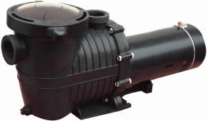
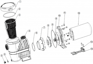
FX PRO II NE4517,NE4518,NE4519,NE4520,NE4521,NE4522PUMP SERIES PARTS BREAKDOWN
| Key | Part Name | Manf. No. | B.W. No. | For Model# |
| 1 | LID W/TRANSPARENT COVER | HTI001 | NEP4209 | All |
| 2 | O-RING | HTI002 | NEP4210 | All |
| 3 | BASKET | HTI003 | NEP4211 | All |
| 4 | STRAINER | HTI004 | NEP4212 | All |
| 5 | DRAIN PLUG | HTI005 | NEP4213 | All |
| DRAIN PLUG O-RING | HTI006 | NEP4214 | All | |
| 6 | O-RING | HTI007 | NEP4215 | All |
| 7 | DIVERSION SETS | HTI008 | NEP4216 | All |
| 8 | IMPELLER OF ITEM#HTI 075/HTI2SP 075 | HTI009 | NEP4217 | NE4519 |
| 8 | IMPELLER OF ITEM#HTI 100/HTI2SP 100 | HTI010 | NEP4218 | NE4517 & NE4520 |
| 8 | IMPELLER OF ITEM#HTI 150/HTI2SP 150 | HTI011 | NEP4219 | NE4518 & NE4521 |
| 8 | IMPELLER OF ITEM#HTI 200/HTI2SP 200 | HTI012 | NEP4220 | NE4522 |
| 9 | O-RING | HTI013 | NEP4221 | All |
| 10 | PUMP HOUSING | HTI014 | NEP4222 | All |
| 11 | SCREW | HTI015 | NEP4223 | All |
| 12 | MOTOR OF ITEM#HTI 100 | HTI017 | NEP4225 | NE4517 |
| 12 | MOTOR OF ITEM#HTI 150 | HTI018 | NEP4226 | NE4518 |
| 12 | MOTOR OF ITEM#HTI2SP 075 | HTI020 | NEP4228 | NE4519 |
| 12 | MOTOR OF ITEM#HTI2SP 100 | HTI021 | NEP4229 | NE4520 |
| 12 | MOTOR OF ITEM#HTI2SP 150 | HTI022 | NEP4230 | NE4521 |
| 12 | MOTOR OF ITEM#HTI2SP 200 | HTI023 | NEP4231 | NE4522 |
| 13 | CARRIER | HTI024 | NEP4232 | All |
page 13
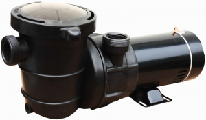
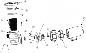
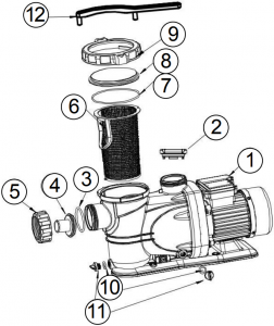
FX PRO II NE4513,NE4514,NE4515,NE4516,NEP4208 PUMP SERIES PARTS BREAKDOWN
| Key | Part Name | Manf. No. | B.W. No. | For Model# |
| 1 | LID | HTA001 | NEP4185 |
All |
| TRANSPARENT COVER | HTA002 | NEP4186 |
All |
|
| 2 | O-RING | HTA003 | NEP4187 |
All |
| 3 | BASKET | HTA004 | NEP4188 |
All |
| 4 | CLAMP | HTA005 | NEP4189 |
All |
| 5 | STRAINER | HTA006 | NEP4190 |
All |
| 6 | DRAIN PLUG | HTA007 | NEP4191 |
All |
| DRAIN PLUG O-RING | HTA008 | NEP4192 |
All |
|
| 7 | O-RING | HTA009 | NEP4193 |
All |
| 8 | SCREW | HTA010 | NEP4194 |
All |
| 9 | PUMP COVER | HTA011 | NEP4195 |
All |
| 10 | O-RING | HTA012 | NEP4196 |
All |
| 11 | IMPELLER OF ITEM#HTA 075/HTA2SP075 | HTA014 | NEP4198 | NE4513 & NE4515 |
| IMPELLER OF ITEM#HTA 100/HTA2SP100 | HTA015 | NEP4199 | NE4514 & NE4516 | |
| IMPELLER OF ITEM#HTA 150/HTA2SP150 | HTA016 | NEP4200 | NEP4208 | |
| 12 | PUMP HOUSING | HTA017 | NEP4201 |
All |
| 13 | MOTOR OF ITEM#HTA 075 | HTA019 | NEP4203 | NE4513 |
| MOTOR OF ITEM#HTA 100 | HTA020 | NEP4204 | NE4514 | |
| MOTOR OF ITEM#HTA2SP 075 | HTA022 | NEP4206 | NE4515 | |
| MOTOR OF ITEM#HTA2SP 100 | HTA023 | NEP4207 | NE4516 | |
| MOTOR OF ITEM#HTA2SP 150 | HTA024 | NEP4208 | NEP4208 |
page 14
FX PRIME SINGLE SPEED PUMPS TECHNICAL DATA
| Model | HP | Voltage | Hertz | Amps | Flow Rate GPM |
| NE4523 | 0.75 | 115 | 60 | 5.5 | 38GPM |
| NF4268 | 0.33 | 115 | 60 | 2.5 | 24GPM |
| NEP4269 | 0.50 | 115 | 60 | 4.5 | 35GPM |
| NE4524 | 1.50 | 115 | 60 | 15.5 | 115GPM |
| NEP4271 | 1.0 | 115 | 60 | 11.0 | 90GPM |
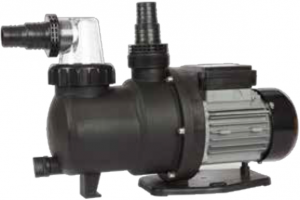
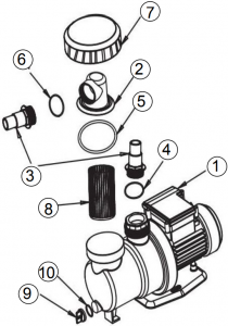
FX PRIME SINGLE SPEED NE4523, NEP4268, NEP4269 PUMP SERIES PARTS BREAKDOWN
| Key | Part Name | Qty | Manf. No. | B.W. No. | For Model# |
| 1 | Water Pump/ Motor | 1 | SPS1A250, 450,550 | NE4523, NEP4268- NEP4269 | NE4523, NEP4268- NEP4269 |
| 2 | Transparent Hair & Lint Strainer | 1 | P00131 | NEP4245 |
All |
| 3 | 1 1/4″- 1 1/2″ Hose Connector | 2 | P00132 | NEP4246 |
All |
| 4 | O-ring “A”- 2 1/4″ | 1 | P00182 | NEP4265 |
All |
| 5 | O-ring “B”- 3″ | 1 | P00183 | NEP4266 |
All |
| 6 | O-ring “C”- 1.5″ | 1 | P00184 | NEP4267 |
All |
| 7 | Strainer Collar | 1 | P00133 | NEP4247 |
All |
| 8 | Strainer Basket | 1 | P00134 | NEP4248 |
All |
| 9 | Pump Drain Cap | 1 | P00135 | NEP4249 |
All |
| 10 | Drain Valve O-ring | 1 | P00136 | NEP4250 |
All |
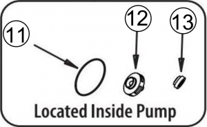
| 11 | Motor Pump Seal | 1 | P00137 | NEP4251 | NE4523 |
| 11 | Motor Pump Seal | 1 | P00138 | NEP4252 | NEP4268 |
| 11 | Motor Pump Seal | 1 | P00138 | NEP4252 | NEP4269 |
| 12 | Impeller Assembly | 1 | P00139 | NEP4253 | NE4523 |
| 12 | Impeller Assembly | 1 | P00140 | NEP4254 | NEP4268 |
| 12 | Impeller Assembly | 1 | P00140 | NEP4254 | NEP4269 |
| 13 | Shaft Seal & Spring Assbly | 1 | P00141 | NEP4255 | NE4523 |
| 13 | Shaft Seal & Spring Assbly | 1 | P00142 | NEP4256 | NEP4268 |
| 13 | Shaft Seal & Spring Assbly | 1 | P00142 | NEP4257 | NEP4269 |
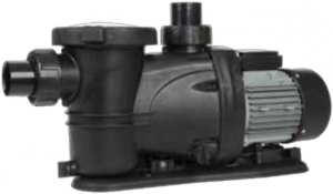
FX PRIME SINGLE SPEED NE4524, NEP4271 PUMP SERIES PARTS BREAKDOWN
| Key | Part Name | Qty | Manf. No. | B.W. No. | For Model# |
| 1 | WATER PUMP | 1 | SPS31600 | NEP4272 | NE4524 & NEP4271 |
| 2 | VALUE BODY | 1 | 3029S3 | NEP4128 | NE4524 & NEP4271 |
| 3 | CONNECTOR O-RING | 1 | 3030S3 | NEP4129 | NE4524 & NEP4271 |
| 4 | PUMP CONNECTOR | 2 | 3031S3 | NEP4130 | NE4524 & NEP4271 |
| 5 | PUMP CONNECTOR NUT | 2 | 3032S3 | NEP4131 | NE4524 & NEP4271 |
| 6 | STRAINER BASKET | 1 | 3033S3 | NEP4132 | NE4524 & NEP4271 |
| 7 | O-SEALING RING | 1 | 3034S3 | NEP4133 | NE4524 & NEP4271 |
| 8 | TRANSPARENT COVER | 1 | 3035S3 | NEP4134 | NE4524 & NEP4271 |
| 9 | CIRCUMGYRATE COVER | 1 | 3036S3 | NEP4135 | NE4524 & NEP4271 |
| 10 | DRAIN VALVE O-RING | 2 | 3037S3 | NEP4136 | NE4524 & NEP4271 |
| 11 | PUMP DRAIN VALVE | 2 | 3038S3 | NEP4137 | NE4524 & NEP4271 |
| 12 | TRANSPARENT COVER CLOSING | 1 | 3039S3 | NE4524 & NEP4271 |
page 15
[xyz-ips snippet=”download-snippet”]