

INSTRUCTIONS FOR:-AIR CURTAINModel:- HCA2
Thank you for purchasing a BN Thermic product. Manufactured to a high standard, this product will, if used according to these instructions and properly maintained, give you years of trouble-free performance. Please ensure instructions remain with your customer for their reference.
![]() REGISTER: PLEASE REGISTER THIS PRODUCT ONLINE TO ACTIVATE YOUR GUARANTEE ATwww.bnthermic.co.uk
REGISTER: PLEASE REGISTER THIS PRODUCT ONLINE TO ACTIVATE YOUR GUARANTEE ATwww.bnthermic.co.uk
 IMPORTANT: PLEASE READ THESE INSTRUCTIONS, NOTE THE SAFE OPERATIONAL REQUIREMENTS, WARNINGS, AND CAUTIONS. USE THIS PRODUCT CORRECTLY, AND WITH CARE FOR THE PURPOSE FOR WHICH IT IS INTENDED. FAILURE TO DO SO MAY CAUSE DAMAGE AND/OR PERSONAL INJURY AND WILL INVALIDATE THE WARRANTY.
Important Note. For an HCA2 air curtain to provide an effective air barrier, a high air velocity is required. The resulting noise output must be considered. For this reason, we do not recommend HCA air curtains for smaller shops or where people are working in close proximity to the entrance.
SAFETY INSTRUCTIONS
ELECTRICAL SAFETY
WARNING! It is the responsibility of the owner and the operator to read, understand and comply with the following:You must check all electrical products, before use, to ensure that they are safe. You must inspect power cables, plugs, sockets, and any other connectors for wear or damage. You must ensure that the risk of electric shock is minimized by the installation of appropriate safety devices. A Residual Current Circuit Breaker (RCCB) should be incorporated in the main distribution board. If in any doubt consult a qualified electrician.
You must also read and understand the following instructions concerning electrical safety.
- The Health & Safety at Work Act 1974 makes owners of electrical appliances responsible for the safe condition of those appliances and the safety of the appliance operators. If in any doubt about electrical safety, contact a qualified electrician.
- Installation should always be carried out by a qualified electrician or a competent person in accordance with current electrical regulations.
- Ensure that the insulation of all the cables on the appliance is undamaged and safe, before connecting it to the power supply.
- Ensure that the cables are always protected against short circuits and overload.
- Regularly inspect the power supply cables for wear or damage and check all connections to ensure that none are loose.
- Important: Ensure that the voltage marked on the appliance matches the power supply to be used.
- DO NOT use worn or damaged cables, plugs, or connectors. Immediately have any faulty item repaired or replaced by a qualified electrician.
- The unit should be protected by a suitably rated isolator and MCB.
- This air curtain is IP20 rated and is suitable for indoor or undercover use only.
- This air curtain must be hard-wired in position.
1.2 GENERAL SAFETY INSTRUCTIONS
✓ Remove all packaging and store it away from children, check the package and air curtain for visible damage or tampering.✓ Familiarise yourself with the applications and limitations of the air curtain.✓ Ensure the air curtain is in good order and condition both physically and electrically before use. If in any doubt, do not use the unit and contact your supplier.✓ Only use recommended attachments and parts. To use unauthorized parts may be dangerous and will invalidate your warranty.✓ Keep tools and other items away from the air curtain when it is in use.✓ Keep children and unauthorised persons away from the air curtain, as it gets hot.✓ Disconnect from mains and allow to cool before attempting any cleaning or maintenance.× DO NOT use in areas where hazardous gasses or dusts may be present.× DO NOT locate the air curtain directly below the power outlet.× DO NOT disassemble the air curtain for any reason. This air curtain must be checked by qualified personnel only.× DO NOT use this air curtain to perform a task for which it has not been designed.❑ WARNING! This air curtain is not equipped with a built-in device to control the room temperature. Do not use this air curtain in a small room if it is occupied by people not capable of leaving the room on their own, unless constant supervision is provided.❑ WARNING! Ensure you observe the safety distances and mounting heights and there is no possibility of inflammable materials coming into contact.

INTRODUCTION & SPECIFICATION
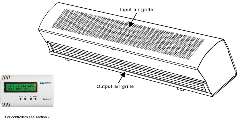
This air curtain produces an invisible barrier across entrances to commercial premises. It will reduce heating costs and minimize the ingress of pollutants. The air curtain uses any one of our SystemX controllers and up to 11 additional air curtains may be connected together and controlled by one controller. Controllers allow on/off, high heat/low heat, and fan-only settings. All air curtains can be wall-mounted or suspended.
| Model | HCA2-09 | HCA2-13 | HCA2-18 |
| Power (High heat setting) | 9kW | 13.5kW | 18kW |
| Input supply | 400V 3Phase + Neutral + Earth | 400V 3Phase + Neutral + Earth | 400V 3Phase + Neutral + Earth |
| Dimensions (W x D x H) | 1113 x 265 x 254mm | 1621 x 265 x 254mm | 2121 x 265 x 254mm |
| Weight | 19.6kg | 25.4kg | 31.9kg |
| Recommended Mounting Height | 2.5 – 4.0M | 2.5 – 4.0M | 2.5 – 4.0M |
DESCRIPTION
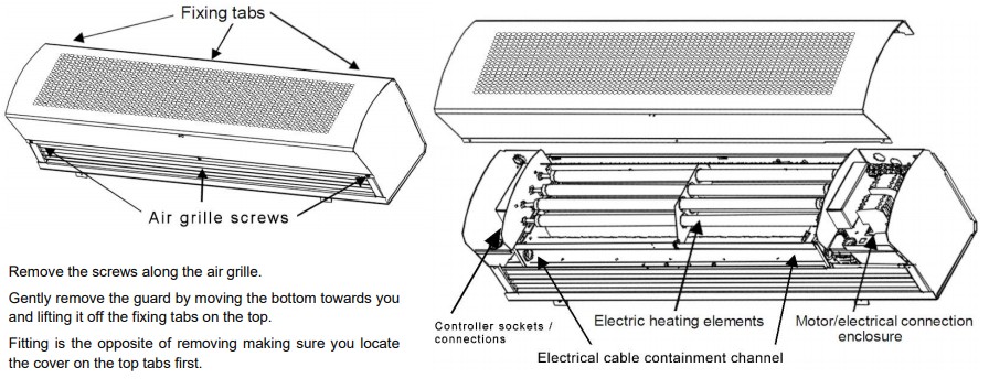
BN Thermic HCA2 air curtains consist of a casing, motor, tangential fan(s), electric heating elements, and electronic controller that facilitates the use of a system controller and the ability to easily daisy chain up to another 11 air curtains. Each air curtain is supplied with a wall mounting bracket as standard. Casings are finished in a durable polyester powder coat. Air is taken through the front input air grille (warmed up if required) and discharged through the output air grille.
IDENTIFICATIONThe air curtain model description is displayed on a silver label found inside the unit casing.
MOUNTING THE AIR CURTAIN
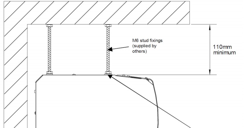
The air curtain can be wall or ceiling mounted at a recommended height of 2.5 – 4m above floor level making sure you leave a minimum of 110mm from the ceiling to the top of the air curtain.
•IMPORTANT! DO NOT mount the air curtain directly below the power isolator.•IMPORTANT! Ensure that the mounting surface/ceiling supports are capable of taking the weight of the air curtain.•IMPORTANT! Always mount the air curtain horizontally. Mounting at any other angle will reduce the air curtain’s life and invalidate the guarantee.•IMPORTANT! The air intake and output areas must be kept completely clear for a minimum of 1m from the front of the air curtain.
The output grille should be installed as close as possible to the top of the doorway opening to ensure minimal air leakage around the door curtain. Ideally, the air curtain should be a minimum of 100mm wider than the doorway on both sides.For correct installation and operation, observe minimum spacing to wall and soffit surface shown in the diagram to the right.
WALL MOUNTING
All models come complete with a wall bracket for vertical wall mounting.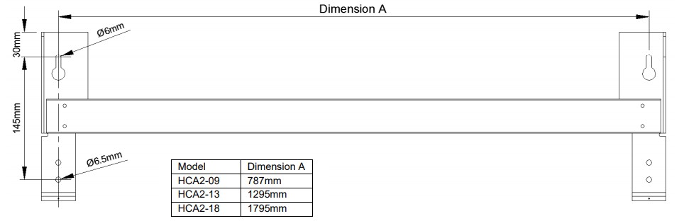
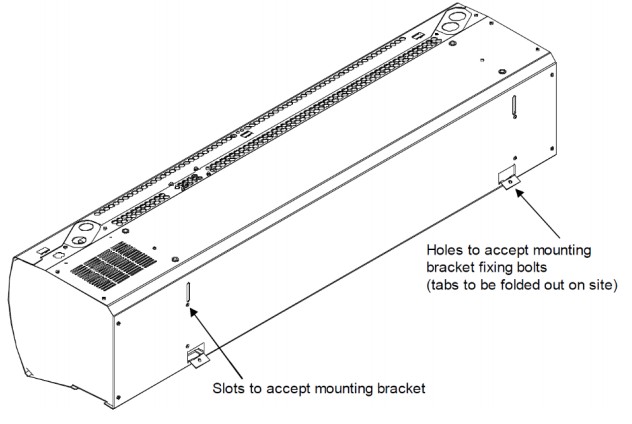
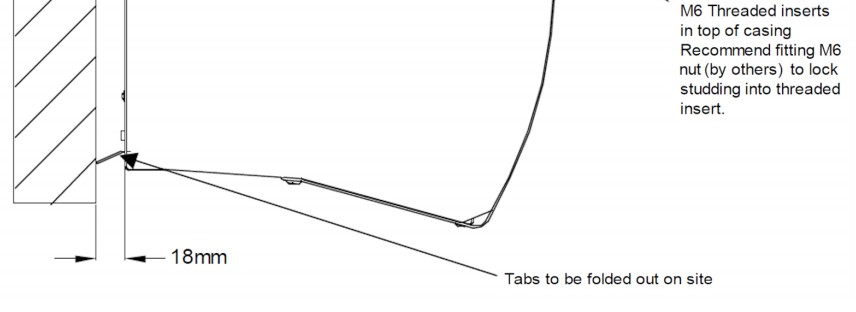
Ensure that the wall will take the total weight of the air curtain. Securely attach the wall mounting plate to the wall using suitable fixings (not supplied) to take the weight of the air curtain.You may find it easier to remove the front cover to expose the electrics before mounting the air curtain onto its bracket. If so, see section 5.Fold the two tabs outwards as shown in the diagram to the right. Using 2 people, lift the air curtain onto the wall bracket and secure it in place by using the 2 x M4 fixing bolts provided. (see drawing below)

CEILING MOUNTING ON DROP RODSThere are 4 x M6 Threaded holes in the top of the air curtain to attach M6 drop rods. Ensure the ceiling will take the total weight of the air curtain and leave a minimum of 110mm between the top of the air curtain and the ceiling for access. See drawings below showing the spacing and positioning of the drop rods. You may find it easier to remove the front cover to expose the electrics before mounting the air curtain onto its drop rods. If so see section 5.Make sure you use a minimum of two persons to lift the air curtain into position. Use M6 nuts to lock each drop rod in position ensuring they will not twist once installed.

REMOVING FRONT COVER
ELECTRICAL CONNECTIONS
Standard Connection and UsePlease make sure you have read the safety instructions and that you are a suitably qualified electrician before continuing. A 400V 3phase 50Hz and Neutral + earth electrical supply is required to power the air curtain.Wiring diagrams on the next page show connections inside the air curtain.Do NOT use power tools to undo or do up terminal screws.Please Note:- Specified cable sizes are for typical installations, correction factors may need to be used when determining actual cable sizes.
| Model | Power Supply – Minimum Cable size (See note above) |
| HCA2-09 | 1.5mm² – 3 Live cables, 1 Neutral cable, and 1 Earth Cable |
| HCA2-13 | 2.5mm² – 3 Live cables, 1 Neutral cable, and 1 Earth Cable |
| HCA2-18 | 4mm² – 3 Live cables, 1 Neutral cable, and 1 Earth Cable |
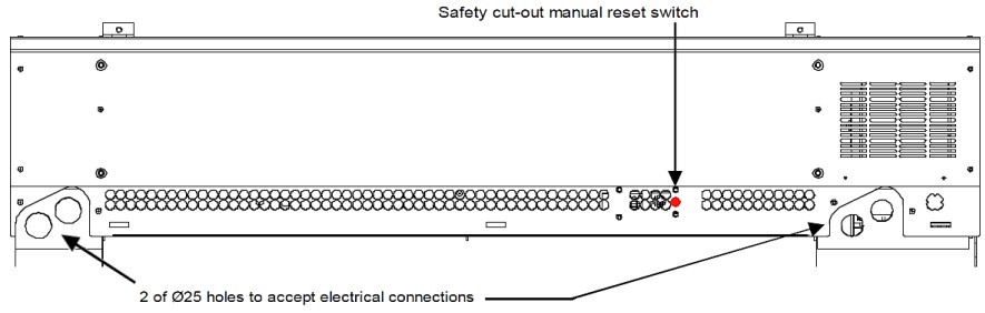
The power supply must be suitably fused with a 3 phase circuit breaker.The air curtain must also have a 3 phase isolator BUT this isolator should NOT be used as a way of turning on and off the air curtain (except in an emergency) due to the fan overrun being disabled causing the safety cut out to trip which will need manual resetting each time.Standard every day on and off switching of the air curtain must be performed using the SystemX wall control box. Two Ø25mm holes are provided on both sides of the air curtain, with a cable channel located above the air output grille, allowing electrical connection to be left or right-handed to suit installation. If using multicore cables, strain relief should be used with proprietary cable glands.
Connect power cables as per wiring diagram overleaf. Connect the air curtain to its controller using a network cable as per section 7 (see overleaf).
PLEASE CHECK ALL CONNECTIONS BEFORE TURNING THEM ON AS INCORRECT WIRING IS NOT COVERED BY THE GUARANTEE

CONTROLLERS
You may connect this air curtain to any one of our range of SystemX controllers using a network cable.We recommend you use our network cables as they have been thoroughly tested and are totally compatible. Problems arising from using non-standard or inferior network cables are not covered by the guarantee.
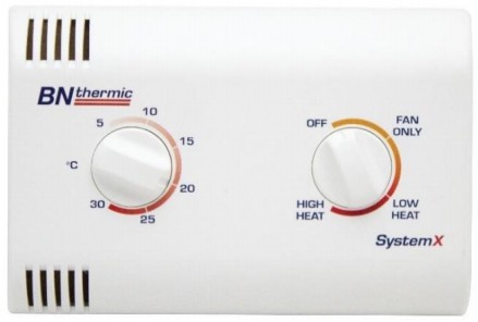
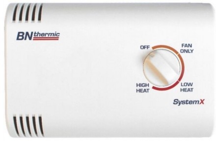
CX1 – Controller with thermostatThermostat range:- 5 to 30⁰CSettings:- on/off/high heat/low heat/Fan onlyMounting:- SurfaceDimensions:-120 x 80 x 40mm Maximum No. of air curtainscontrolled:- 12
Notes:- The internal “Fan” switch needs to be set to “ON” allowing the fan to continue running creating a curtain of air when the heating elements turn off. See controller instructions for more information.
CX2 – Controller with tamper-resistant thermostatThermostat range:- 5 to 30⁰CSettings:- on/off/high heat/low heat/Fan onlyMounting:- SurfaceDimensions:-120 x 80 x 40mmMaximum No. of air curtains controlled:- 12
Notes:- The internal “Fan” switch needs to be set to “ON” allowing the fan to continue running creating a curtain of air when the heating elements turn off. See controller instructions for more information.
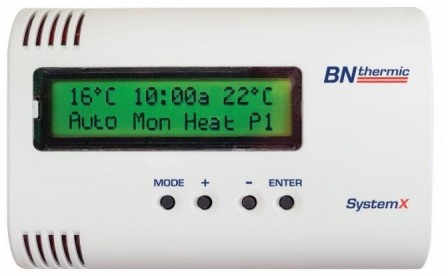
CX6 – Programmable controllerThermostat range:- 5 to 30⁰C 7 days or 5 + 2 days programming Up to 6 programable events per daySettings:- on/off/high heat/low heat/fan onlyMounting:- SurfaceDimensions:-120 x 80 x 40mmMaximum No. of air curtains controlled:- 12
Notes:- The internal default “Fan” setting needs to be set to “ON” allowing the fan to continue running creating a curtain of air when the heating elements turn off. See controller instructions for more information.
With all the above controllers when the ambient temperature reaches the set point the heating elements will turn off BUT the fan will continue to run ensuring you still have a curtain of air present. If the ambient temperature drops below the set point of the thermostat the heating elements will come on again.
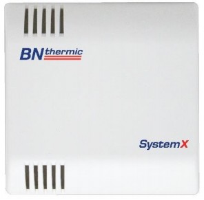
CXS – Optional remote sensorCan be used with all the above controllers when connected override the controller’s built-in sensor.
CX3 – Controller without a thermostatSettings:- on/off/high heat/low heat/Fan onlyMounting:- SurfaceDimensions:-120 x 80 x 40mmMaximum No. of air curtains controlled:- 12

CONNECTING THE CONTROLLER
Please read the instructions enclosed with each controller for complete details on mounting/connecting your controller to the air curtain.The network sockets (connection points) are found on the left-hand end of the air curtains. Either socket (see diagram, section 5, page 5) may be used for the controller. The other socket is used when connecting other air curtains to the system.There are knockouts on the casing to allow the network cable connections to be made. Connect all network cables before replacing the covers onto the air curtains.If adding more than one air curtain to the controller you will require an additional network cable for each additional air curtain.Up to 11 additional air curtains may be connected together, giving a maximum of 12 air curtains per controller.
MAINTENANCE
Note: Before examining or carrying out any maintenance, ensure the air curtain has cooled down and is disconnected from the mains supply.The air curtains are intended to operate for many years, problem-free. All moving parts are factory lubricated and therefore should require no service.A visual inspection of the unit and its internal components should be carried out once every 6 months.
Electric elements – The elements do not require any maintenance other than a visual inspection, however, when cool, they may be vacuumed clean to remove dust using a soft brush attachment.
Fuse – The mains inlet connector incorporates a 5A fuse which does not require any maintenance other than a visual inspection. Replace with a fuse of the same type and value.
Fan motor – The fan motor has a ‘seal for life’ bearing which does not require any maintenance other than a visual inspection however they may be vacuumed clean to remove dust using a soft brush attachment. All accessible surfaces can be wiped with a dry cloth.
Controls – Check remote on/off and speed switches for satisfactory operation.
Check fan run-on and safety cut-out for satisfactory operation (located top of casing). If the safety cut-out trips regularly in normal operation; check the operation of the fan and that the airflow through the unit is not restricted by dust and the inlet or outlet is not obstructed. If the problem persists, please contact us for further help.
When the air curtain is first turned on after cleaning, an unusual odor may be noted. This is due to the dust particles which inevitably will be disturbed and be burnt off from the heating element.
If in any doubt always consult a qualified electrician for advice.
OVER-TEMPERATURE PROTECTION / FUSE REPLACEMENT
Two thermal protection switches are fitted to the air curtain.
One thermal switch provides the fan over-run. The fan will either continue to run after the unit is switched off on the wall control switch, until the air temperature in the casing drops below 50°C, or will switch the fan back on after the unit is turned off should the case temperature rise above 50°C for a short period.
The second manual reset thermal switch provides the safety cut-out. Should the air temperature in the casing rise above 60°C this will cause the safety cut out to trip. The safety cut-out can be reset by pressing the red button located on top of the unit. If the safety cut-out trips regularly; check the operation of the fan and that the airflow through the unit is not restricted by dust and the inlet or outlet is not obstructed. If the problem persists, please contact us.
The air curtain control circuit is protected by an internal fuse. The fuse holder is located near the contactors on the electrical tray. Should the fuse fail, replace it with another 5A fuse. If this replacement fuse fails seek professional help.
NOTE: It is our policy to continually improve products and as such we reserve the right to alter data, specifications, and component parts without prior notice.
 This product conforms to EU Directive 2002/96/EC.This appliance bears the symbol of the crossed waste bin. This indicates that, at the end of its useful life, it must not be disposed of as domestic waste, but must be taken to a collection center for waste electrical and electronic equipment. It is the user’s responsibility to dispose of this appliance through the appropriate channels. Failure to do so may incur penalties established by-laws governing waste disposal.
IMPORTANT: No liability is accepted for incorrect use of this product.WARRANTY: Your BN Thermic product is guaranteed for one year from the date of purchase. We will repairor replace at our discretion any part found to be defective. Our warranty does not cover corrosion. We cannot assume any consequential liability. This guarantee in no way prejudices your rights under common law and is offered as an addition to consumer liability rights.REGISTER: Activate your warranty by registering online at www.bnthermic.co.uk and retain this installation data for future reference.
| BN Thermic Ltd,34 Stephenson Way,Crawley, RH10 1TNTel: +44 (0) 1293 547361Email: [email protected]Web: www.bnthermic.co.uk |
References
[xyz-ips snippet=”download-snippet”]