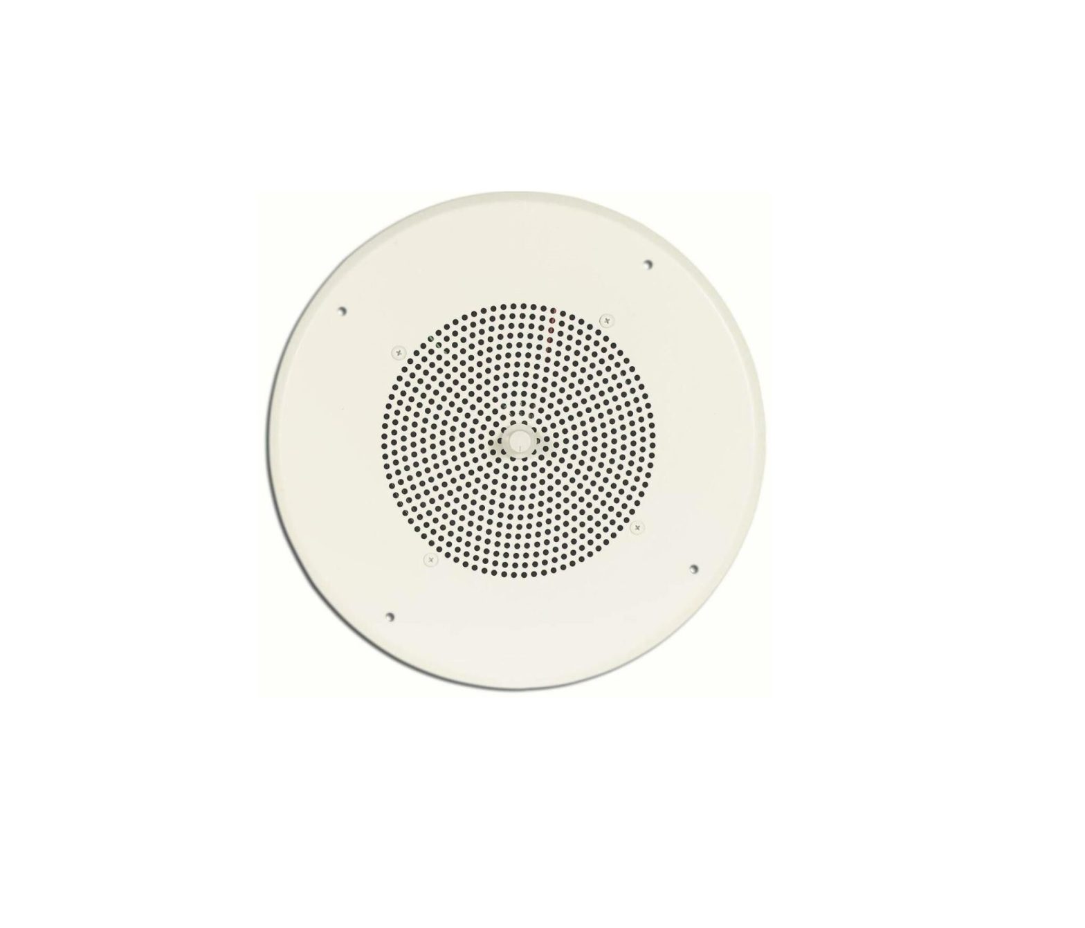
BOGEN CS1EZ Easy Design Ceiling
Speaker Installation Guide

Speaker Layout
CEILING VIEW
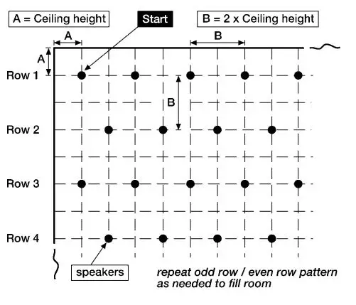
The layout of the speakers should be planned before installation begins. Layout starts in one corner of the room. The first speaker should be positioned from each wall a distance approximately equal to the ceiling height of the room.The next speaker in row 1 should be spaced a distance approximately equal to twice the height of the ceiling. Each additional speaker in the row should use this same spacing.
Row 2 starts at twice the ceiling height distance from row 1 and twice the ceiling height from the wall. The other speakers in this row are also spaced at twice the ceiling height.
Row 3 is again spaced at twice the ceiling height from the previous row. The first speaker starting this row is positioned at one ceiling height distance from the wall (similar to row 1).
Continue this pattern of alternating rows until the room is covered.
The spacing of the speakers can be adjusted so that the speakers are evenly spaced in a row and aesthetically pleasing.
Additional Hardware
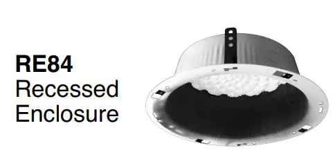 RE84 Recessed Enclosure – The RE84 is an optional back box for ceiling speakers. UL Listed for use where ceiling plenum is part of an air handling system. The RE84 also includes attachment tabs allowing the enclosure to be supported from structures other than the actual ceiling grid.
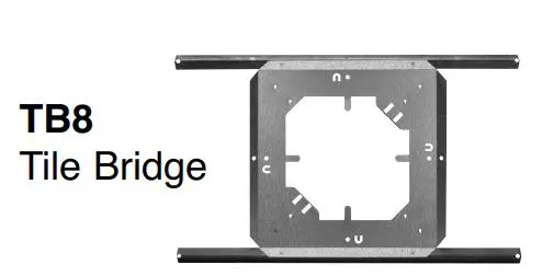
TB8 Tile Bridge – The TB8 supports the weight of the speaker and recessed enclosure. This is also the item to which the speaker mounting screws attach. The TB8 is required for each speaker assembly installed.
54-5043-01C 1209© 1999 Bogey Communications Inc. All rights reserved.Specifications subject to change without notice.
Speaker Installation
STEP 1 – Remove the tile from ceiling and centre the TB8 tile bridge on the back. Use the tile bridge to trace out, and then cut an 8-1/2″ square hole.
NOTE: It is sometimes more efficient to stack up a number of ceiling tiles and then cut the speaker opening in a number of them at once.
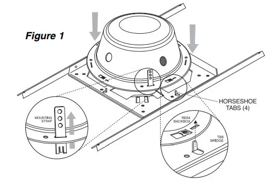
STEP 2 – If using the optional RE84 Recessed Enclosure, bend up the 4 horseshoe tabs (see figure 1 on the TB8). Position the TB8 over the hole in the tile and push down the locator tabs (see figure 2).
STEP 3 – Using the 4 supplied screws, attach the CS1EZ to the TB8 using the 4 clips in the corners of the opening on the TB8 as nuts.
NOTE: Only tighten the screws until the grille is snug against the tile. Over tightening will cause the screws to dimple the grille.
STEP 4a – If not using RE84 Recessed Enclosure: Make the electrical connections using the 2 screw terminals on the CS1EZ. The suggested amplifier connections are:
70V terminal – 70V HOTCOM terminal – 70V COMMON
NOTE: The speaker will also work perfectly well with these connections reversed. However, it is important to be consistent in the wiring of the speakers in the system. If adjacent speakers have reversed wiring connections, they will tend to cancel each others bass response, diminishing the sound quality.
STEP 4b – If using RE84 Recessed Enclosure: Install an entry fitting to a knock-out in the RE84 to accommodate the plenum cable. Feed cable through RE84 entry and clamp. Make speaker connections as in 4a. All connections and any splices must be made within the enclosure. Place the RE84 over the horseshoe tabs (see step 2) and twist the tabs with pliers to secure the RE84 to the TB8.
STEP 5 – Place the assembled ceiling tile back into the ceiling.

Limited Warranty; Exclusion of Certain DamagesThe CS1EZ is warranted to be free from defects in material or workmanship for three (3) years from the date of sale to the original purchaser. Any part of the product covered by this warranty that, with normal installation and use, becomes defective will be repaired or replaced by Bogen, at our option, provided the product is shipped insured and prepaid to: Bogen Factory Service Department, 50 Spring Street, Ramsey, NJ 07446, USA. The product(s) will be returned to you freight prepaid. This warranty does not extend to any of our products that have been subjected to abuse, misuse, improper storage, neglect, accident, improper installation or have been modified or repaired or altered in any manner whatsoever, or where the serial number or date code has been removed or defaced.
THE FOREGOING LIMITED WARRANTY IS BOGEN’S SOLE AND EXCLUSIVE WARRANTY AND THE PURCHASER’S SOLE AND EXCLUSIVE REMEDY. BOGEN MAKES NO OTHER WARRANTIES OF ANY KIND, EITHER EXPRESS OR IMPLIED, AND ALL IMPLIED WARRANTIES OF MERCHANTABILITY OR FITNESS FOR A PARTICULAR PURPOSE ARE HEREBY DISCLAIMED AND EXCLUDED TO THE MAXIMUM EXTENT ALLOWABLE BY LAW. Bogen’s liability arising out of the manufacture, sale or supplying of products or their use or disposition, whether based upon warranty, contract, tort or otherwise, shall be limited to the price of the product. IN NO EVENT SHALL BOGEN BE LIABLE FOR SPECIAL, INCIDENTAL OR CONSEQUENTIAL DAMAGES (INCLUDING, BUT NOT LIMITED TO, LOSS OF PROFITS, LOSS OF DATA OR LOSS OF USE DAMAGES) ARISING OUT OF THE MANUFACTURE, SALE OR SUPPLYING OF PRODUCTS, EVEN IF BOGEN HAS BEEN ADVISED OF THE POSSIBILITY OF SUCH DAMAGES OR LOSSES. Some States do not allow the exclusion or limitation of incidental or consequential damages, so the above limitation or exclusion may not apply to you. This warranty gives you specific legal rights, and you may also have other rights which vary from State to State.
Products that are out of warranty will also be repaired by the Bogen Factory Service Department — same address as above or call 201-934-8500. The parts and labour involved in these repairs are warranted for 90 days when repaired by the Bogen Factory Service Department. All shipping charges in addition to parts and labour charges will be at the owner’s expense. All returns require a Return Authorization number.7/22/2008

References
[xyz-ips snippet=”download-snippet”]

