![]()
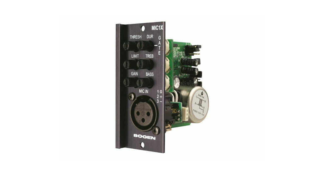
MIC1XMicrophone InputModule
Features
- Transformer-balanced
- Gain/Trim control
- Bass and treble
- Gating
- Gating threshold and duration adjustments
- Variable Threshold Limiter
- Limiter Activity LED
- 4 levels of available priority
- Can be muted from higher priority modules
- Can mute lower priority modules
© 2001 Bogen Communications, Inc.54-2052-01C 0701Specifications are subject to change without notice.
Module Installation
- Turn off all power to the unit.
- Make all necessary jumper selections.
- Position module in front of desired module bay opening, making sure that the module is right-side up.
- Slide module onto card guide rails. Make sure that both the top and bottom guides are engaged.
- Push the module into the bay until the faceplate contacts the unit’s chassis.
- Use the two screws included securing the module to the unit.
WARNING:Turn off power to the unit and make all jumper selections before installing the module in the unit.
Jumper Selections
* Priority LevelThis module can respond to 4 different levels of priority. Priority 1 is the highest priority. It mutes modules with lower priorities and is never muted. Priority 2 can be muted by Priority 1 modules and mutes modules set for 3 or 4. Priority 3 is muted by either Priority 1 or 2 modules and mutes Priority 4 modules. Priority 4 modules are muted by all higher priority modules.* The number of priority levels available is determined by the amplifier the modules are used in.
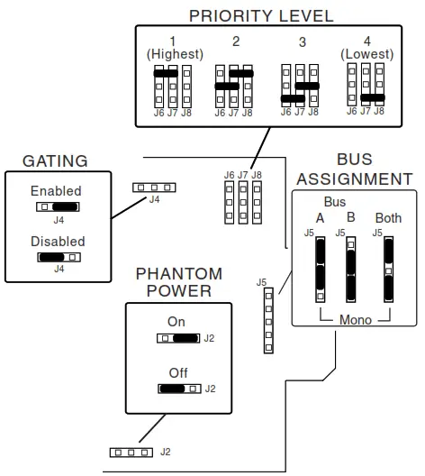
GatingGating (turning off) of the module’s output when insufficient audio is present at the input can be disabled. detection of audio for the purpose of muting lower priority modules is always active regardless of jumper setting.
Phantom Power24V phantom power can be supplied to condenser microphones when the jumper is set to ON position. Leave OFF for dynamic mics.Bus AssignmentThis module can be set to operate so that the MIC signal can be sent to the main unit’s A bus, B bus, or both buses.
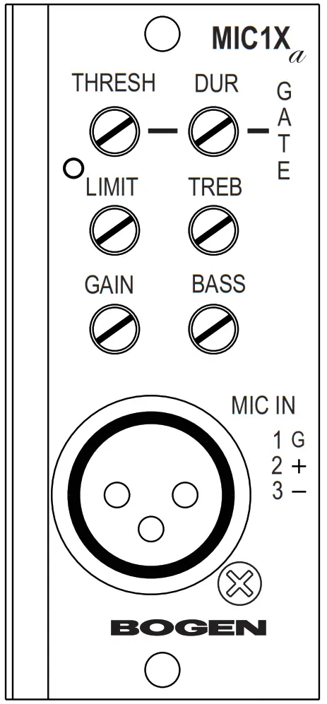
Gate – Threshold (Thresh)Controls the minimum necessary input signal level to turn the module’s output on and apply a signal to the main unit’s buses. Clockwise rotation increases the necessary signal level required to produce output and mute lower priority modules.
Limiter (Limit)Sets the signal level threshold at which the module will begin to limit the level of its output signal. Clockwise rotation will allow more output signal before limiting, counterclockwise rotation will allow less. The limiter monitors the module’s output signal level, so increasing Gain will affect when limiting takes place. An LED indicates when the Limiter is active.
GainProvides control over the level of the input signal that can be applied to the internal signal buses of the main unit. Allows a way to balance the input levels of various devices so that the main unit controls can be set to relatively uniform or optimum levels.
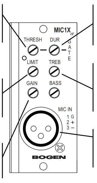 Gate – Duration (Dur)Controls the amount of time the output and mute signal of the module remains applied to the main unit’s buses after the input signal falls below the required minimum signal level (set by the threshold control).
Bass & Treble (Treb)Provides separate controls for Bass and Treble cut and boost. The Bass control affects frequencies below 100 Hz and Treble affects frequencies above 8 kHz. Clockwise rotation provides boost, counterclockwise rotation provides cut. Center position provides no effect.
ConnectionsUses standard female XLR to make connections to the module’s input. The input is low-impedance, transformer-balanced for excellent noise and ground loop immunity.
Block Diagram
 report this ad
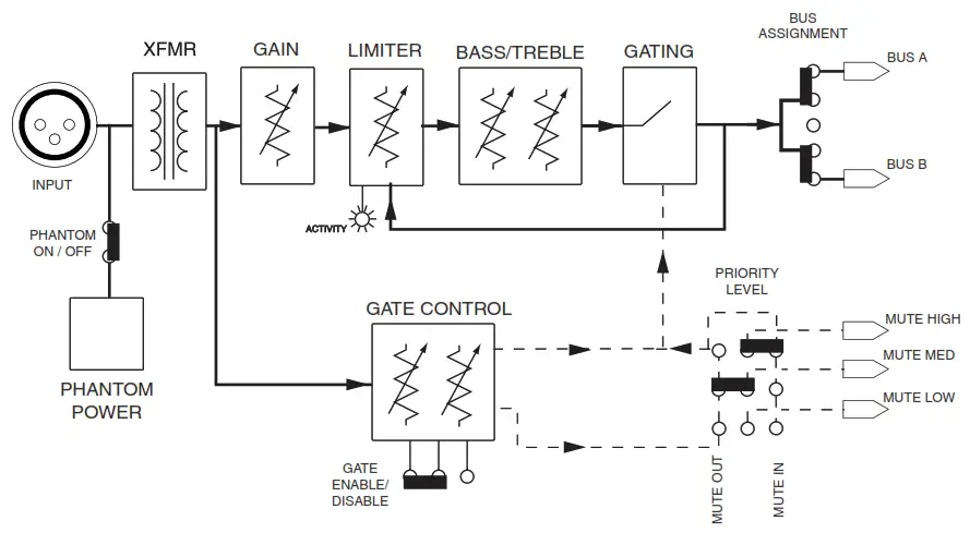
References
[xyz-ips snippet=”download-snippet”]