![]()
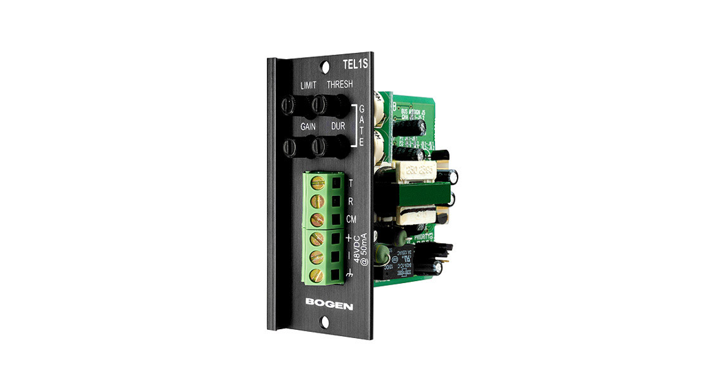
TEL1STelephone InterfaceModule
Features
- Loop start trunk interface
- Ground start trunk interface
- Page port interface
- Transformer-isolated
- Gain/Trim control
- Output signal gating
- Gating threshold and duration adjustments
- Variable threshold limiter
- 4 Levels of available priority
- Can be muted from higher priority modules
- Can mute lower priority modules
© 2003 Bogen Communications, Inc.Specifications subject to change without notice54-2055-01D 0808
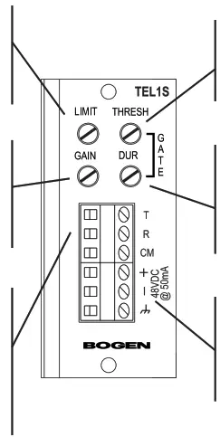
Module Installation
- Turn off all power to the unit.
- Make all necessary jumper selections.
- Position the module in front of desired module bay opening, making sure that the module is right-side up.
- Slide the module onto the card guide rails. Make sure that both the top and bottom guides are engaged.
- Push the module into the bay until the faceplate contacts the unit’s chassis.
- Use the two screws included securing the module to the unit.
WARNING:Turn off power to the unit and make all jumper selections before installing the module in the unit.
Jumper Selections
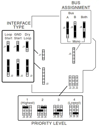
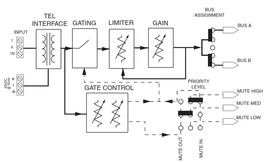
Bus AssignmentThis module can be set to operate so that the input signal can be sent to the main unit’s A bus, B bus, or both buses.
Interface TypeDry Loop – Use with page ports. Activated by audio activity on the telephone line.Loop Start – Use when interfacing to PBX loop-start trunks or dedicated telephones. Requires connection of external power supply (see Block Diagram for more info).Ground Start – Use only on PBX ground-start trunks. Requires connection of external power supply and connection to PBX ground.
* Priority LevelThis module can respond to 4 different levels of priority. Priority 1 is the highest priority. It mutes modules with lower priorities and is never muted. Priority 2 can be muted by Priority 1 modules and mutes modules set for 3 or 4. Priority 3 is muted by either Priority 1 or 2 modules and mutes Priority 4 modules. Priority 4 modules are muted by all higher priority modules.* The number of priority levels available is determined by the amplifier the modules are used in.
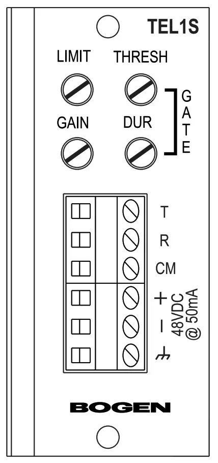
Limiter (Limit)Sets the signal level threshold at which the module will begin to limit the level of its output signal. Clockwise rotation will allow more output signal before limiting, counterclockwise rotation will allow less. The limiter monitors the module’s output signal level, so increasing gain will affect when limiting takes place.
GainProvides control over the level of the input signal that can be applied to the internal signal buses of the main unit. Allows a way to balance the input levels of various devices so that the main unit controls can be set to relatively uniform or optimum levels. Clockwise rotation will increase gain, counterclockwise rotation decreases gain.
Telephone System ConnectionsConnect the telephone system’s Tipline to the “T” terminal and the Ring line to the “R” terminal. When interfacing to a ground start trunk, also connect a wire from the PBX’s ground to the module’s “CM” terminal. In some cases, the power supply’s ground connection alone will be adequate. For Dry Loop (Page Ports), connect the audio pair to the module’s “T” & “R” terminals (polarity insensitive). No power supply isnecessary. The module is audio-activated so a contact pair from the page port is not needed.
Gate – Threshold (Thresh)Controls the minimum necessary input signal level to turn the module’s output on and apply a signal to the main unit’s buses. Clockwise rotation increases the necessary signal level required to produce output and mute lower priority modules.
Gate – Duration (Dur)Controls the amount of time the output and mute signal of the module remains applied to the main unit’s buses after the input signal falls below the required minimum signal level (set by the threshold control). Clockwise rotation will increase time duration, counterclockwise will decrease duration within a 0.5s to 5s range.
Power Supply ConnectionsInterfacing to a loop or ground start trunk requires an external 48V power supply to be connected to the module. Make connections as marked. The ground connection is optional but can be helpful when interfacing with ground-start trunks. Bogen Model PRS48 is recommended.
Connections
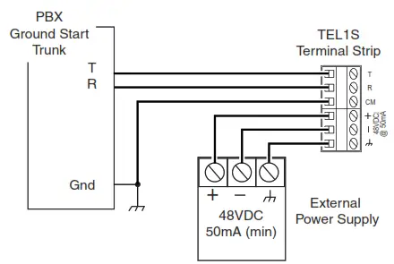
Ground Start Interface Troubleshooting
- Check that trunk is a Ground Start type. Try other trunk-style connections. If there is DCvoltage on the telephone line, it is a station line and cannot be interfaced with this module.
- Check jumper settings.
- Check power supply connections and operation.
- Check the connection between CM terminal and the PBX’s ground.
- Try reversing T & R connections.
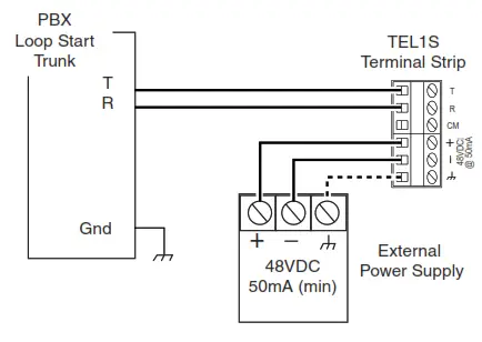 Loop Start Interface Troubleshooting
- Check that trunk is a Loop Start type. Try other trunk-style connections. If there is DC voltage on the telephone line, it is a station line and cannot be interfaced with this module.
- Check jumper settings.
- Check power supply connections and operation.
- Try reversing T & R connections.
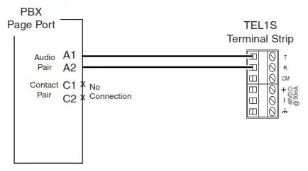
Page Port Interface Troubleshooting
- Check that there is no DC voltage on the telephone line. If there is, it is a station line and cannot be interfaced with this module.
- Check jumper settings.
- Check that audio is present at audio pair leads of page port.
- Adjust Threshold control on the module.
Block Diagram
 report this ad
![]()
COMMUNICATIONS, INS.www.bogen.com
References
[xyz-ips snippet=”download-snippet”]