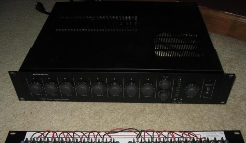
BOGEN V35 Power Vector Amplifier
NoticeEvery effort was made to ensure that the information in this guide was complete and accurate at the time of printing. However, information is subject to change.
Important Safety InformationWARNING: To Reduce The Risk of Fire Or Electric Shock, Do Not Expose This Apparatus To Rain Or Moisture.Always follow these basic safety precautions when installing and using the unit:
- Read these instructions.
- Keep these instructions.
- Heed all warnings.
- Follow all instructions.
- Do not use this apparatus near water.
- Clean only with dry cloth.
- DO NOT block any ventilation openings. Install in accordance with the manufacturer’s instructions.
- Do not install near any heat sources such as radiators, heat registers, stoves, or other apparatus (including amplifiers) that produce heat.
- Do not defeat the safety purpose of the polarized or grounding-type plug. A polarized plug has two blades with one wider than the other. A grounding-type plug has two blades and a third grounding prong. The wide blade, or the third prong, are provided for your safety. If the provided plug does not fit into your outlet, consult an electrician for replacement of the obsolete outlet.
- Protect the power cord from being walked on or pinched, particularly at plugs, convenience receptacles, and the point where they exit from the apparatus.
- Only use attachments/accessories specified by the manufacturer.
- Unplug this apparatus during lightning storms or when unused for long periods of time.
- Refer all servicing to qualified service personnel. Servicing is required when the apparatus has been damaged in any way, such as power supply cord or plug is damaged, liquid has been spilled or objects have fallen into the apparatus, the apparatus has been exposed to rain or moisture, does not operate normally, or has been dropped.
Panel Descriptions
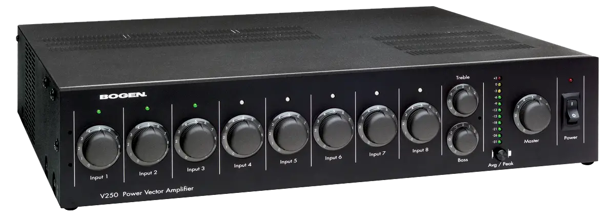
Power Vector Front Panel
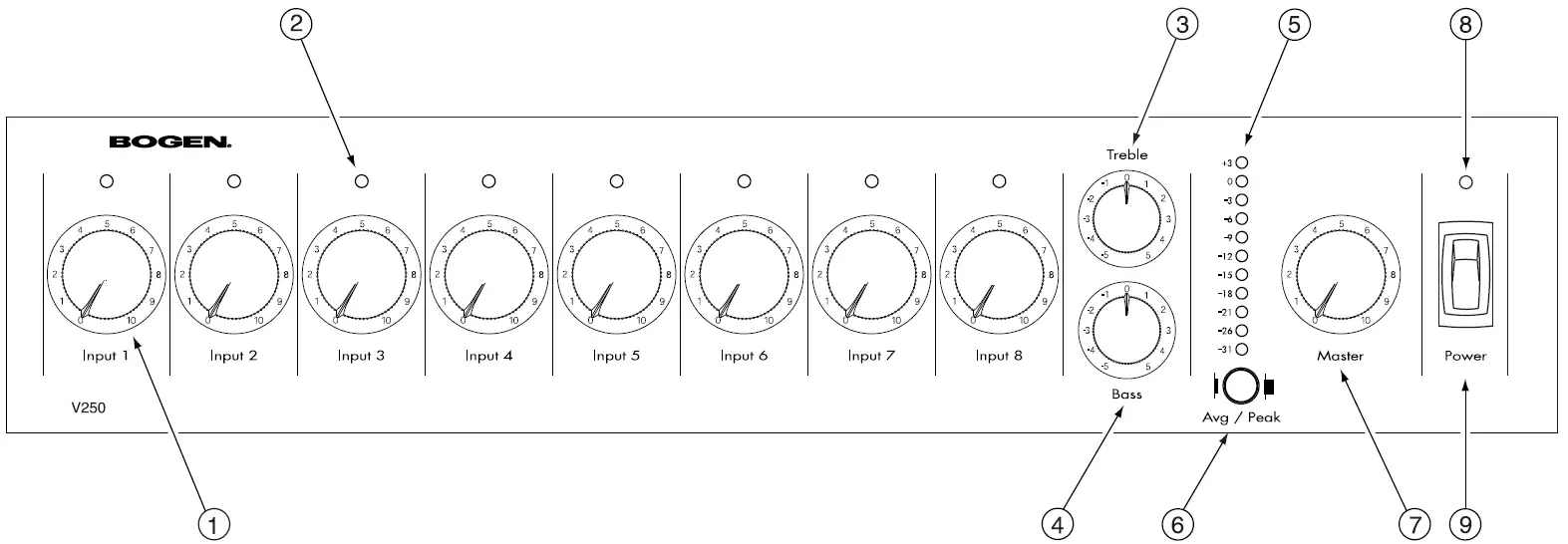
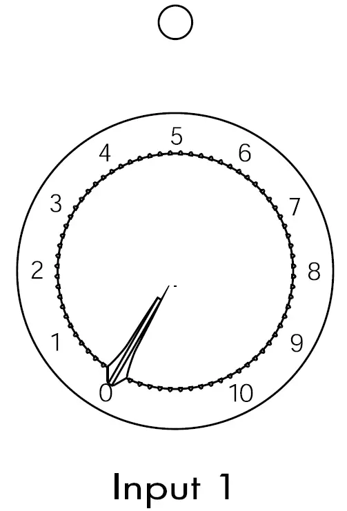
- Input Volume ControlEach of the 8 inputs is controlled by an independent volume control.
- Signal / Clip IndicatorA single two-color LED located above each channel’s volume control indicates the audio activity of that channel’s input. Green indicates signal present at the input; red indicates clipping of the input signal.
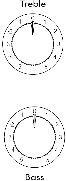
- Treble ControlControls the amount of cut or boost of treble frequencies above 10 kHz.
- Bass ControlControls the amount of cut or boost of bass frequencies below 100 Hz.
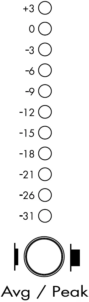
- LED Output MeterAn 11-segment LED output level meter monitors the output level of the power amplifier.
- Average / Peak SwitchThis switch determines whether the LED Output Meter registers the average or peak level of the amplifier’s output.
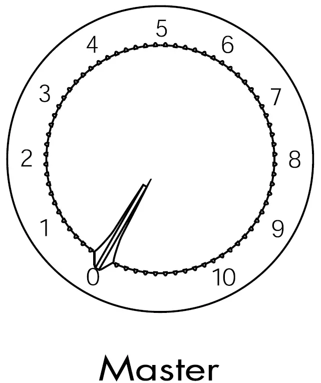
- Master Volume ControlControls overall level of mixed input signals.
- Power IndicatorAn LED indicates AC power status.
- Power SwitchControls AC power to the amplifier.
Power Vector Rear Panel
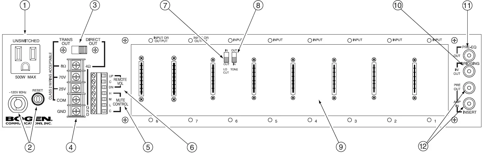
- AC ReceptacleA grounded, unswitched AC convenience receptacle with a 500W maximum capacity is provided for external equipment.
- AC Line Cord and Circuit BreakerA grounded, 3-wire AC line cord provides power to the amplifier and is protected by a resettable circuit breaker.
- Trans Output / Direct Out SelectorAllows selection of either transformer-coupled outputs (70V, 25V, and 8-ohm) or a direct low-impedance (4-ohm minimum) output. A locking device is included to avoid accidental switching.
- Speaker Output Barrier StripA 5-position barrier strip, with clamping washers, provides connections for speaker loads.
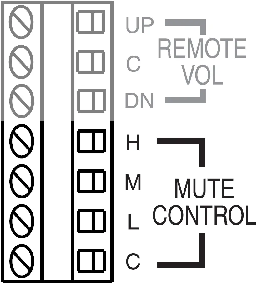
- Mute Control TerminalsProvides access to mute buses for external control and system expansion.
- Remote Volume Control TerminalsThree terminals are provided for connection of a remote station to control the amplifier’s motorized Master Volume Control.
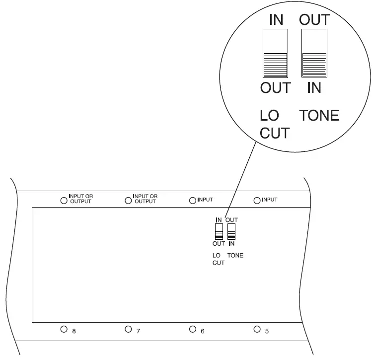
- Low-Cut SwitchA slide switch (located in module bay 6) that allows roll off of frequencies below 125 Hz.
- Tone Control Bypass SwitchA slide switch (located in module bay 6) that allows the effects of the bass and treble controls to be bypassed.
- Module BaysThe amplifier has eight module bays, all of which can accommodate input modules, with two bays (bays 7 and 8) that can accommodate either input or output modules.
- Bridging JackAn RCA connector that allows the bridging of Power Vectors together for system expansion.
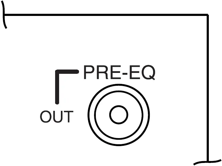
- Pre-EQ OutputAn unbalanced RCA buffer output whose signal includes all volume controls, tone controls, and output module signal processing, but before (pre-EQ) any external signal-processing equipment connected to the Signal-Processing Insert jacks.
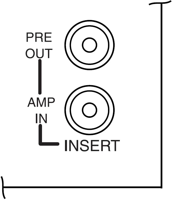
- Insert JacksA pair of RCA connectors allow external equipment to be inserted between the pre-amp output and the power amp input. Inserting a plug into the jack labeled “IN” automatically breaks the internal connection between the amplifier’s pre-amp section and power amp section. The insert connections are unbalanced.
Installation
Package Contents
- Power Vector Amplifier
- Switch Lock
- Instruction Manual
- Module Covers (8)
- 12 mm Module Cover Screws (16)
Ventilation and Mounting
Models V250 and V150When rack or table mounting models V250 and V150, allow a minimum clearance of 1-1/4″ on the left side of the unit for proper ventilation of the fan exhaust and a minimum top and bottom clearance of 1/2″. The right side has no specific clearance requirement. These are minimum acceptable clearances, though the more space provided on the left side, top, and bottom, the better.
Models V100, V60, and V35When rack or table mounting models V100, V60, and V35, which are passively cooled, allow a minimum clearance of 1/2″ for the bottom (set by the height of the unit’s feet) and a minimum of 1″ from the top to other obstructions. The sides have no specific clearance requirement. These are minimum acceptable clearances, though the more space provided, both top and bottom, the better.
Rack MountingWhen stacking equipment in a rack, the amplifier should either be on the bottom of the stack or above equipment that does not produce heat. This will ensure that cool air is available to the unit’s heat sinks. A rack mount bracket kit (model RPK87) is available for the Power Vector series of amplifiers.
Shelf/Table MountingWhen using a shelf or table mount, the amplifier should stand alone with no equipment on top of it or below it, especially for the V100, V60, and V35 models. If the amplifier must be stacked with other equipment, care must be taken to ensure that all the minimum clearance distances are met and that the equipment below the amplifier produces little significant heat. Rubber feet are installed on the amplifier to allow it to be placed on a tabletop.
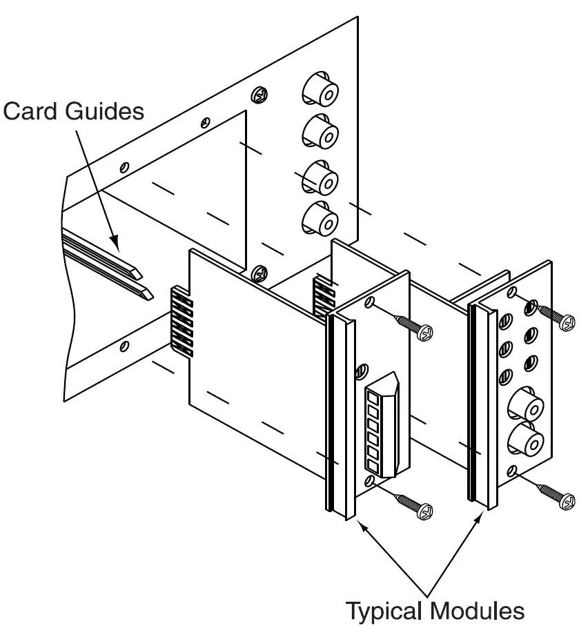
Module Installation
Eight module bays are available to accept Bogen’s new advanced input modules. Module bays 7 & 8 can also accommodate Bogen’s new advanced output modules, thereby allowing users to customize the amplifier to suit the needs of the installation. (The bays will not accept Bogen’s older style plug-in modules.)Before installing a module, read the instructions included with the module and make the desired jumper setting changes.The modules are installed by simply sliding them along the card guides inside the module bays until the faceplate firmly sits against the chassis, then use the two screws supplied with the module to secure it to the chassis.
– CAUTION –DO NOT FORCE MODULES
- Modules should slide in easily.
- Output modules will not fit in bays 1-6.
- Output modules can only be installed in bays 7 & 8.
- Output modules have 8 contacts on each side.
- Input modules have 6 contacts on each side.
- Older style Bogen input modules (41/2″ in length) are not usable in the Power Vector amps.
Modules
Output Modules
FunctionalityThe Power Vector series of amplifiers accepts Bogen signal-processing output modules, which offer a cost effective and convenient way to add specific signal-processing capability into a system. When an output module is installed, the mix bus signal is automatically rerouted through the output module, whose capabilities further process the signal before it is presented to the power amplifier section.Up to 2 output modules can be installed in a Power Vector amplifier using module bays 7 & 8 (these bays accept either output or input modules). When two output modules are installed, their signal-processing effects are cascaded. The mix bus signal will first pass through the output module in module bay 7 and then through the output module in bay 8. In some instances, the order in which the signal processing is applied is important and can be determined by the module installation order.Output modules automatically insert themselves into the signal path between the mix bus and power amp stage, so no further connections are required beyond simply inserting the modules. Most Bogen output modules include an unbalanced, Hi-Z input. This input feeds directly to the amplifier’s mix bus through the front level control for the particular module bay and is not processed by the output module directly. The input is included so that the input function of the module bay is not lost when an output module is installed.
Input Modules
FunctionalityThe Power Vector series of amplifiers accepts Bogen’s new advanced input modules, which provide a wide range of input types allowing the amplifier inputs to be custom configured in both type and number for a particular application. Input modules can be installed into any of the 8 module bays and do not have to be installed in any particular bay order. The front panel volume control for that number bay will control the mix level of that input module. In addition to a host of module specific features, each input module has a priority jumper section for creating a priority hierarchy between different inputs installed in the amplifier.
PrioritiesThe Power Vector series of amplifiers allows inputs to be prioritized at four different levels. The Bogen input modules contain circuitry that can cause their outputs to be muted in response to higher priority control signals from other input modules. Each input module also contains circuitry that sends a mute control signal out to other modules when it becomes active (all input modules become “active” when they receive an audio input). Active modules may be prevented from sending their audio onto the mix bus by a higher priority module that is also active.Input priorities are set through a simple jumper field on the module. It is also possible not to assign a priority level to an input module. By doing so, that module will never be muted by another input module in the amplifier.
Connections
Speakers
Transformer-Coupled Speaker ConnectionsTransformer-coupled, constant voltage speaker loads are connected to their respective load type (i.e., 70V speakers to the 70V terminal, 25V speakers to the 25V terminals) and the COM terminal. Make sure the selector switch is in the TRANS OUT position. A separate 8-ohm terminal is provided to drive 8-ohm (low-impedance) speakers through an output transformer tap.The speaker terminals can accept up to a #10 spade lug and have integral clamping plates that make wiring easier.
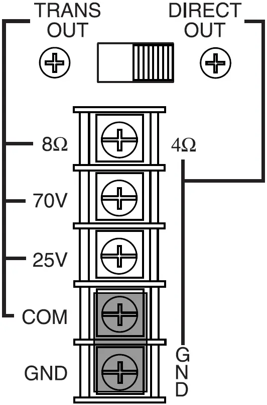
4-Ohm Low-Impedance Speaker ConnectionsA low-impedance (4Ω) speaker load can be driven directly without transformer coupling by connecting the load to the 4Ω terminal and the GND terminal. Make sure the selector switch is in the DIRECT OUT position.Bypassing the output transformer and driving the speaker load directly provides the advantage of better bass response. To maximize the power delivered to the speakers, their combined load impedance should be 4 ohms. Connecting higher load impedances is electrically acceptable, but the mismatch in load impedance will cause the speaker load to only receive a portion of the power that the amplifier is capable of delivering. It is not acceptable to connect low-impedance speakers to the 70V and 25V outputs.
![]() Typical connections to a 70V transformer-coupled speaker
Typical connections to a 70V transformer-coupled speaker
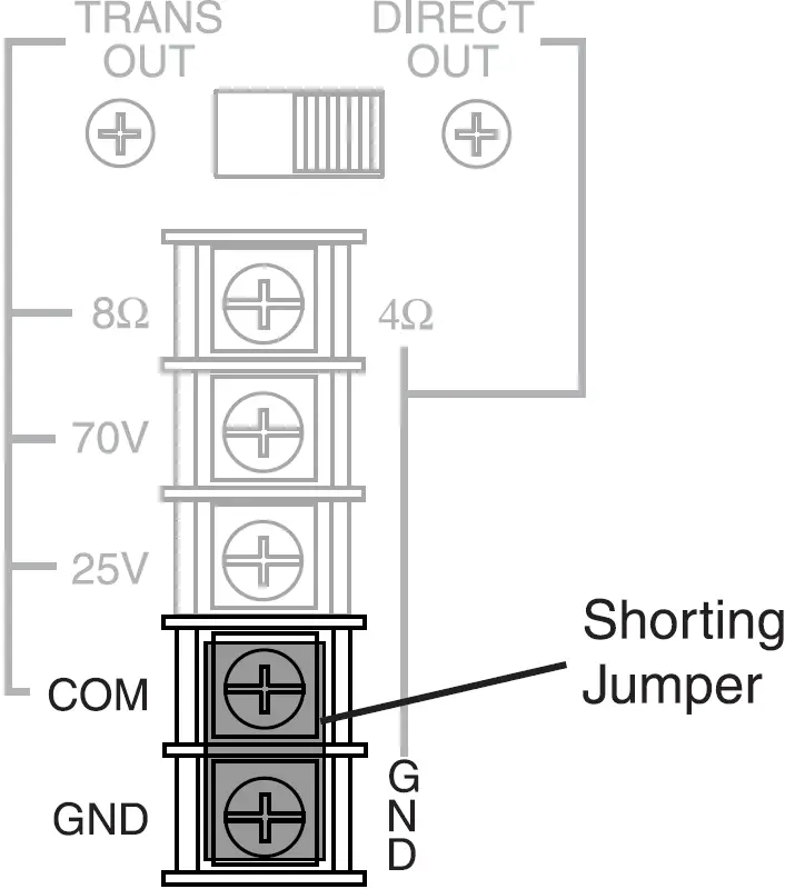
![]() Typical connections to a low-impedance (non-transformer-coupled) speaker load
Typical connections to a low-impedance (non-transformer-coupled) speaker load
COM and GND TerminalsA shorting jumper typically connects the COM and GND terminals of the amplifier together. The COM terminal is a common lead from the output transformer. For the transformer-coupled speaker output to work, one of the speaker load leads must be connected to this terminal. The GND terminal is a connection to the system’s electrical ground and used when driving loads in the Direct Out mode.Connecting the GND to the COM terminal when using the transformer-coupled outputs references the transformer output to ground. Disconnecting the GND terminal from COM allows the transformer output to float electrically. This is sometimes useful under certain conditions where a ground connection is undesirable. It is generally a good idea to short the GND to the COM terminal regardless of output type (Trans or Direct).
Remote Volume Control
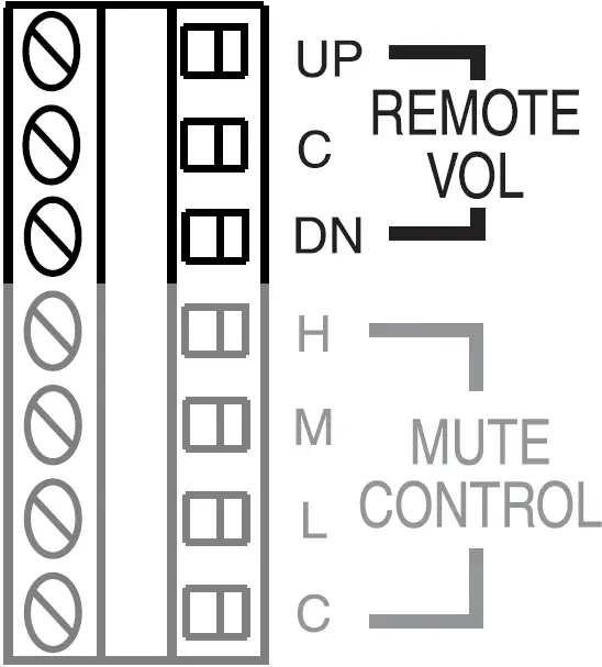
Three terminals are provided for remote control of the Master Volume control on the front panel. This control is motorized, allowing full con-trol over the setting of the master volume. Shorting the UP terminal with the C terminal will rotate the Master Volume control in a clockwise direction, increasing the volume level. Shorting the DN terminal to the C terminal will cause the Master Volume control to rotate in a counter-clockwise direction and decrease the level of the Master Volume control. The impedance of the shorting connections must be less than 100 ohms in order to operate the control. The Bogen Remote Volume Control Panel (Model RVCP) provides a simple and elegant means of remote control. Alternatively, a SPDT spring-loaded, center off switch or two SPST push-button switches can provide the necessary contacts for remote control.
Pre-EQ Output
An unbalanced RCA connector provides a buffered signal level output for use by external equipment. This output signal includes all internal signal processing, including master volume control, output modules processing, tone controls, and low-cut filtering. It does not include any external signal processing that may be provided through the Signal-Processing Inserts.
Signal-Processing Inserts
A set of unbalanced RCA connectors provides a means to insert external signal-processing equipment between the output of the Power Vector Amplifier’s mixer section and its power amp section. The RCA connector labeled OUT provides a signal from the amplifier’s mixer section. This output signal encompasses all internal signal processing, including master volume control, output modules processing, tone controls, and low-cut filtering. The connector labeled IN provides an input to the amplifier’s power amplifier section. The internal connection between the amplifier’s mixer section and power amp section is automatically broken whenever an RCA plug is inserted into the IN connector.
Mute Control
Each priority bus (High, Medium, and Low) can be externally activated. This allows priority buses of two or more Power Vector units to be linked together for system expansion purposes. A particular mute priority can be externally forced by shorting that priority’s bus terminal to the C terminal of the Mute Control (the C terminal is the system ground). Forcing the H priority bus this way will mute all modules except for modules set for priority level 1 (highest priority). Forcing the M priority bus will mute modules set for priority levels 3 or 4, but not levels 1 or 2, and forcing the L priority bus will only mute modules set at priority level 4. See section on Bridging and illustration below.
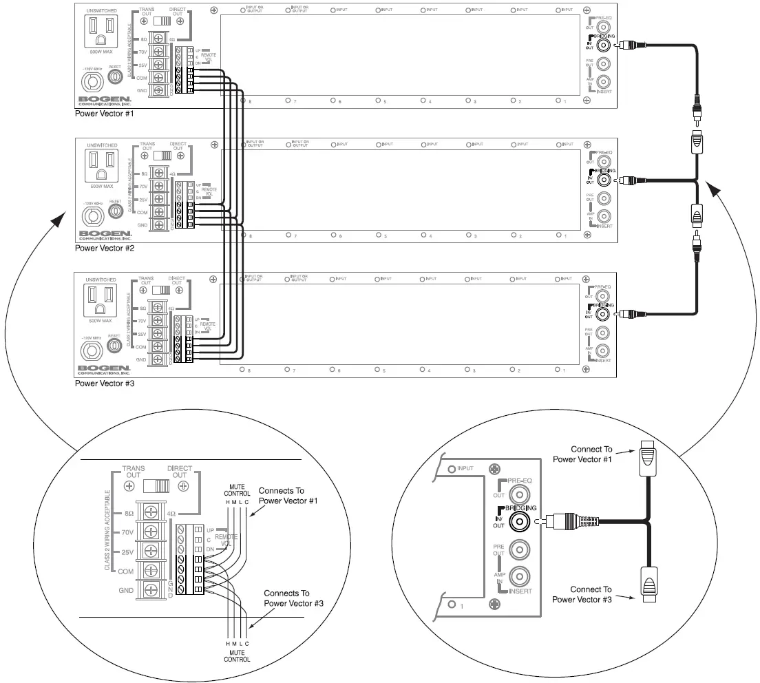
Bridging
This connector makes the Power Vector’s mix bus available externally and allows the connecting of Power Vector units for system expansion and simple room combining.This function is bi-directional. Any signal received will be amplified and any signal sent can be used by another Power Vector amp. The signal levels at the bridging jack will drop by one-half with two Power Vectors tied together and by two-thirds with three units tied together. Because of the attenuation of the bridging signal, due to the signal loading of other Power Vectors, it is not recommended that more than three units be connected together. See Mute Control section and the illustration below for additional information.

System Expansion of Power Vector Amplifiers
Using the bridging RCA connector, it is possible to connect two or more Power Vector amplifiers. It is not recommended that more than three amplifiers be bridged together due to bridging loss. When connecting mute control functions, make certain that the wiring is consistent (H to H, M to M, and so forth). See illustration below.
Operation
Front Panel Controls & Indicators
Input Volume ControlsEach input module may be individually controlled by its corresponding volume control knob.
Signal / Clip IndicatorA single LED located above each channel’s volume control indicates the audio activity of that channel’s input. Green indicates signal present at the input. Red indicates that the input signal coming from the input module into the amp is clipping and distorted. This is caused by either an input signal that is too high or an input module volume control (gain) that is set too high.
Bass and Treble ControlsThe treble control has a cut/boost range of +/- 10 dB at frequencies above 10 kHz and provides a roll off after 20 kHz to reduce gain above the audio range.The bass control has a cut/boost range of +/- 10 dB at frequencies below 100 Hz. When driving speakers using the direct-coupled output terminals, the bass filter’s response is flat to 20 Hz. When driving speakers using the transformer-coupled output terminals, the Power Vector amplifier automatically changes the bass filter’s response to a bandpass shape to reduce the level of bass frequencies below 40 Hz. This filter shape helps to avoid overdriving the output transformer with low frequency signals that may cause noticeable distortion due to magnetic saturation of the transformer’s core.
Master Volume ControlThe overall volume level of the amplifier is set by a Master Volume control. The Master Volume control is motorized and can be controlled by manually adjusting the knob or by a remotely-mounted control station. Connections and requirements for the remote control station are described in the Connections section, under Remote Volume Control.
Average / Peak Switch & LED Output MeterThe LED Output Meter is an 11-segment meter that registers either the average or the peak level of the amplifier’s output signal. A red indicator is provided at the +3 dB level to indicate amplifier clipping. Amber indicators at the 0 dB and -3 dB levels indicate high amplifier output levels. The remaining 8 indicators (green) provide an indication of the output signal’s dynamics. The meter can be set to read either the average output signal level or the peak output signal levels by using the Average / Peak Switch at the bottom of the meter. In for average; out for peak.
Power Switch / Power IndicatorThe AC power to the amplifier is controlled by the Power rocker switch. A red LED indicator lights to confirm the power on status of the amplifier.
Rear Panel Controls
Load Selector SwitchA large slide switch above the amplifier’s output barrier strip determines transformer-coupled or direct output operation. The setting of this switch controls which amplifier output terminals are active and what type of filter shape will be used for the bass control. See the connections section for more information about the load selector switch.
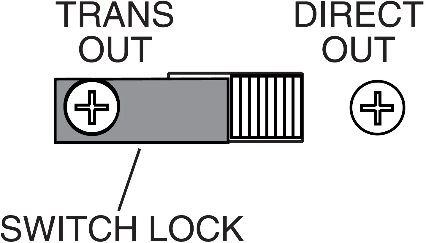
A removable switch lock is provided with the amplifier to prevent accidental changes in switch position. To set the lock, loosen the screw opposite the desired switch position. Slide the lock under the loosened screw and align it with the switch. Tighten the screw making sure the lock has not shifted.
Other Controls (Located In Module Bay 6)
Tone Control Bypass SwitchA slide switch that can bypass the effects of the Bass and Treble controls is located on the back plane of module bay 6. It is sometimes desirable to bypass the tone controls when other forms of system equalization are used. A screwdriver can be used to set the switch. The switch must be set before a module is installed in this bay.
Low-Cut SwitchThe Power Vector Amplifier provides a low-cut filter that rolls off frequencies below 125 Hz. The slide switch for this function is located on the back plane of module bay 6. A screwdriver can be used to set the switch. The switch must be set before a module is installed in this bay.
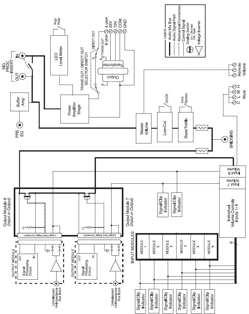
Block Diagram
Troubleshooting
|
PROBLEM |
CONDITION |
CAUSE |
| NO SOUND | Power Indicator LED is off. |
|
| Power Indicator LED is red. Input Signal / Clip LED is off. |
|
|
| Power Indicator LED is red. Input Signal / Clip LED is green. LED Output Meter is off. |
|
|
| Power Indicator LED is red. Input Signal / Clip LED is green. LED Output Meter is operating. |
|
|
| DISTORTED SOUND | Power Indicator LED is red. Input Signal / Clip LED is green. Volume Controls are turned up and show little activity.Unit is extremely hot. |
|
| Power Indicator LED is red. Input Signal / Clip LED is green. LED Output Meter is not in red. |
|
|
| Power Indicator LED is red. Input Signal / Clip LED is red. LED Output Meter is not in red. |
|
|
| Power Indicator LED is red. Input Signal / Clip LED is green. LED Output Meter in red. |
|
|
| POOR LOW FREQ. RESPONSE (NO BASS) | Power Indicator LED is red. Input / Signal Clip LED is green. LED Output Meter not in red. |
|
| NOISE/HUM | Power Indicator LED is red. Volume controls are in normal operational position. |
|
Limited Warranty
The Bogen Power Vector Amplifiers are warranted to be free from defects in material and workmanship for three (3) years from the date of sale to the original purchaser. Any part of the product covered by this warranty that, with normal installation and use, becomes defective (as confirmed by Bogen upon inspection) during the applicable warranty period, will be repaired or replaced by Bogen, at Bogen’s option, provided the product is shipped insured and prepaid to: Bogen Factory Service Department, 50 Spring Street, Ramsey, NJ 07446, USA. Repaired or replacement product will be returned to you freight prepaid. This warranty does not extend to any of our products that have been subjected to abuse, misuse, improper storage, neglect, accident, improper installation or have been modified or repaired or altered in any manner whatsoever, or where the serial number or date code has been removed or defaced.THE FOREGOING LIMITED WARRANTY IS BOGEN’S SOLE AND EXCLUSIVE WARRANTY AND THE PURCHASER’S SOLE AND EXCLUSIVE REMEDY. BOGEN MAKES NO OTHER WARRANTIES OF ANY KIND, EITHER EXPRESS OR IMPLIED, AND ALL IMPLIED WARRANTIES OF MERCHANTABILITY OR FITNESS FOR A PARTICULAR PURPOSE ARE HEREBY DISCLAIMED AND EXCLUDED TO THE MAXIMUM EXTENT ALLOWABLE BY LAW. Bogen’s liability arising out of the manufacture, sale or supplying of products or their use or disposition, whether based upon warranty, contract, tort or other-wise, shall be limited to the price of the product. IN NO EVENT SHALL BOGEN BE LIABLE FOR SPECIAL, INCIDENTAL OR CONSEQUENTIAL DAMAGES (INCLUDING, BUT NOT LIMITED TO, LOSS OF PROFITS, LOSS OF DATA OR LOSS OF USE DAMAGES) ARISING OUT OF THE MANUFACTURE, SALE OR SUPPLYING OF PRODUCTS, EVEN IF BOGEN HAS BEEN ADVISED OF THE POSSIBILITY OF SUCH DAMAGES OR LOSSES. Some States do not allow the exclusion or limitation of incidental or consequential damages, so the above limitation or exclusion may not apply to you. This warranty gives you specific legal rights, and you may also have other rights which vary from State to State.Products that are out of warranty will also be repaired by the Bogen Factory Service Department – same address as above or call 201-934-8500. The parts and labor involved in these repairs are warranted for 90 days when repaired by the Bogen Factory Service Department. All shipping charges in addition to parts and labor charges will be at the owner’s expense. All returns require a Return Authorization number. For most efficient warranty or repair service, please include a description of the failure.
Accessories
A variety of accessories are available.
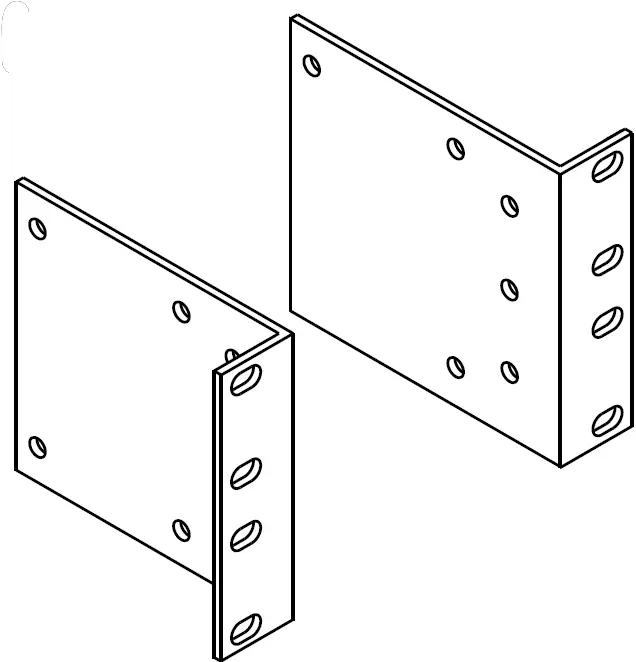
RPK87 – Rack Mounting Kit
- Adapts Power Vector Mixer for 19″ rack mounting
- Heavy gauge steel construction
- Fits Power Vector Mixer into 2 rack spaces (31/2″)
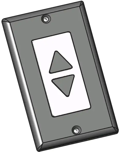
RVCP – Remote Volume Control Panel
- Push-button operation of motorized master volume control
- Fits in standard single gang electrical box
- Decora style cover plate
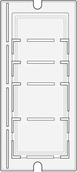
PVSC – Power Vector Security Cover
- Prevents tampering with system settings
- Power and meter switches accessible
- Simple installation
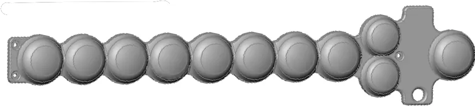
PVMC – Power Vector Module Cover
- Prevents tampering with module settings
- Break-off sections to allow access to connectors while preventing access to control settings
- Covers unused module slots
 report this ad
![]()
References
[xyz-ips snippet=”download-snippet”]