

BOSCH BMX055 Desktop Development

About the BMX055
The BMX055 consists of BMA255, BMG160 and BMM150 in a single chip.
BMA255 is an advanced, ultra-small, tri-axial, low-g acceleration sensor with digital interfaces, aiming for low- power consumer electronics applications. Featuring 12 bit digital resolution, the BMX055 allows low noise measurement of accelerations in 3 perpendicular axes and thus senses tilt, motion, shock and vibration in cellular phones, handhelds, computer peripherals, man-machine interfaces, virtual reality features and game controllers.
The BMG160 is a three-axes-gyroscope device. It consists of a MEMS element and an ASIC within one package. It is capable to measure angular rates in three perpendicular room dimensions X, Y and Z-axis and to provide the corresponding the output signals
BMM150 is a three axis MEMS magnetometer. The magnetometer measures the components of the earth’s magnetic field (the geomagnetic field).
The packaging and interfaces of the BMM150 have been designed to match a multitude of hardware requirements. As the sensor features an ultra-small footprint and a flat package, it is ingeniously suited for mobile applications.
The BMM150 offers ultra-low voltage operation (VDD voltage range from 1.62V to 3.6V, VDDIO voltage range 1.2V to 3.6V) and can be programmed to optimize functionality, performance and power consumption in customer specific applications. The programmable interrupt engine sets new standards in terms of flexibility.
The BMM150 senses data ready, low threshold, high threshold and overflow in cell phones, handhelds, computer peripherals, man-machine interfaces, virtual reality features and game controllers. BMM150 sensor specific details can be referred in BMM150 sensor data sheet.
Key features of BMX055
BMA255
- Digital interface SPI (4-wire/3-wire) and I²C interfaces
- Programmable functionality Acceleration ranges ±2g/±4g/±8g/±16g
- On-chip FIFO Integrated FIFO with a depth of 32 frames
- On-chip interrupt controller
- Motion triggered interrupt-signal generation
- Ultra-low-power
- Low current consumption short wakeup time advanced features for system power management
- RoHS, halogen free
BMG160
- 3-axis gyroscopic sensor evaluation
- Switchable full-scale ranges – in total 5 ranges
- Internal low-pass filters 10, 25, 50, 100, 200 Hz
- 16-Bit resolution
- Adjustable on-chip oscillator
- Self-wakeup
- Wake-up time in fast power mode is only 10 ms
- Interrupt engine
- SPI & I²C interface supported.
BMM150
- User programmable high/low magnetic field detection interrupt
- Low-power consumption
- SPI (4-wire/3-wire) and I²C interfaces
- Programmable interrupt application
- Short wake-up time, advanced features for system power management
- Magnetic field range ±1300uT(x,y-axis), 2500uT(z-axis)
- Self test and advanced self test capability
- RoHS compliant, Pb-free
- LGA package (3 mm x 3 mm x 0.9 mm)
Getting Started
The below sections highlight the procedure to set up connections between BMX055, DD2.0 UI, and the PC.
Setting Up the board-PC connection
The procedure to connect sensor to PC via USB is as below:
- Install DD2.0 UI.
- Insert the shuttle board and application board.
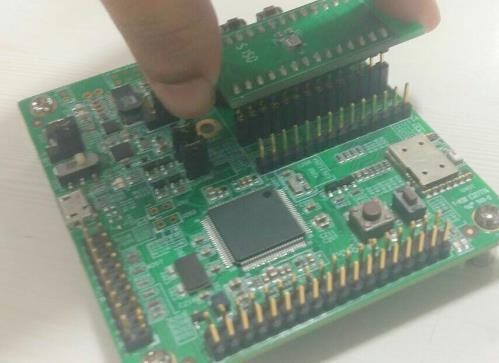
Figure 1 : Insert sensor
Connect the board and PC using a USB cable/Bluetooth.
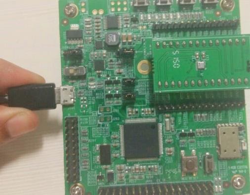
Figure 2 : Connect board and PC
Turn the on/off switch ON. The LED glows.
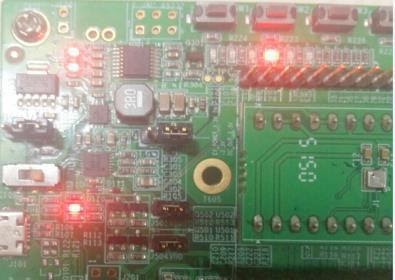
Figure 3 : Connection complete
Startup View
To start the DD2.0 UI software:
- Click Start -> Programs -> Development Desktop 2.0.
- Double click the DD2.0 UI software icon on the desktop.
The Graphical User Interface (GUI) of the software is as seen below:
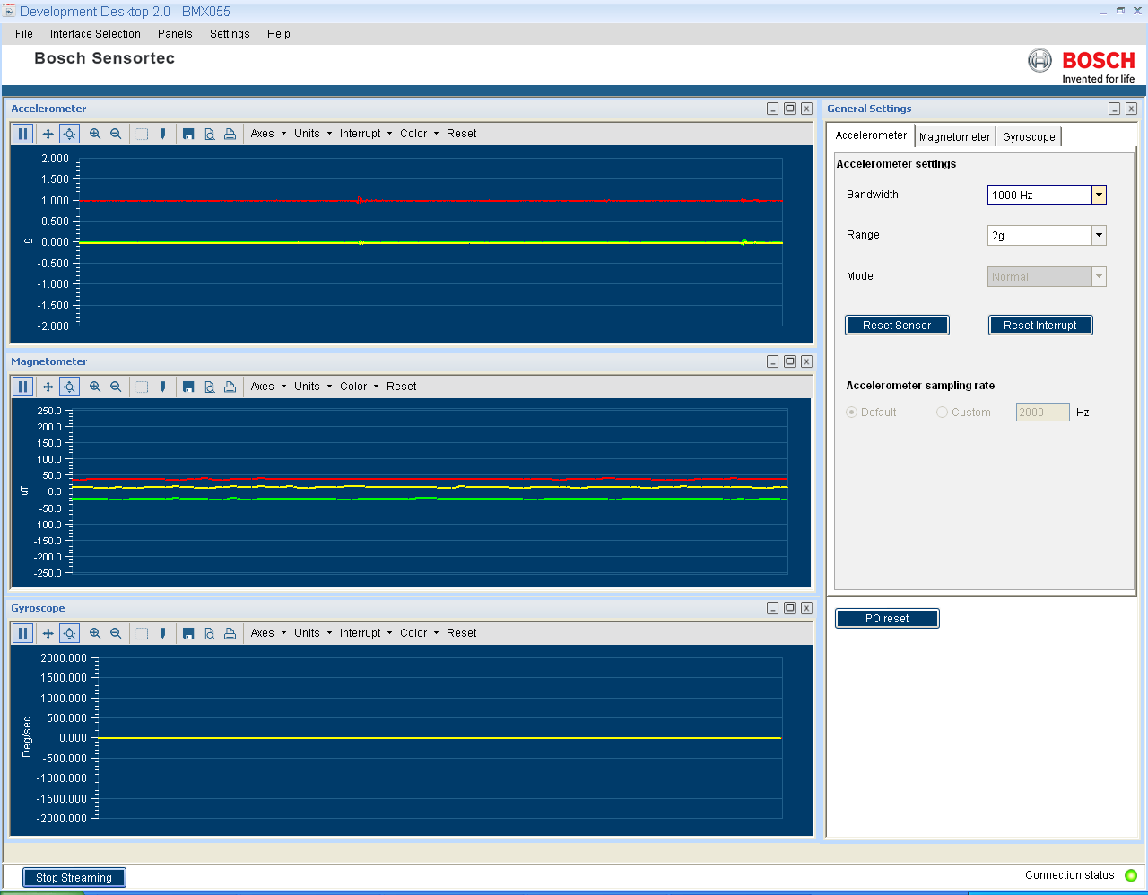
Figure 4 : DD2.0 UI Startup View
When the PC and board are connected, the Communication Status glows green as shown below:
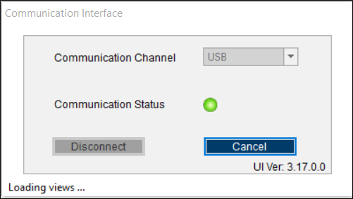
Figure 5 : Communication Status
- The communication status is also indicated at the bottom right of the GUI at all times:
- Other menu options include:
- File
- Interface Selection
- Panels
- Settings
- Help
These menu options are explained in detail in the following sections.
Upgrading Firmware
To upgrade the firmware of DD2.0 UI to match the current version, follow the steps below:
- Click Menu -> Settings-> Firmware Upgrade. The following window appears:
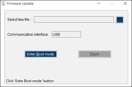
Figure 6 : Firmware upgrade window
- Click Enter Boot mode.

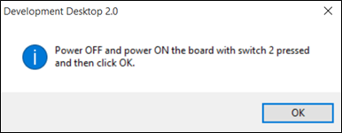
Figure 7 : Application Boot Loader
- Switch off board, and press Switch 2.In Application board, all four LEDs will glow simultaneously.
- Click OK.
- All four LEDs will glow simultaneously.
- Press OK.
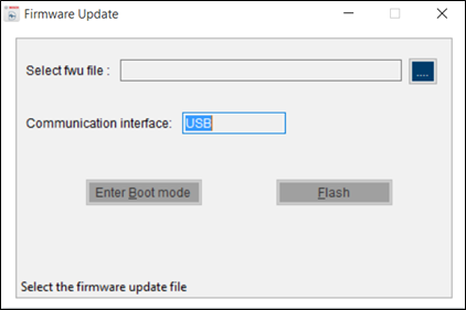 Figure 8 : Boot mode Detected
- Select the default firmware update file (*.fwu2) from the DD2.0 UI installation directory in the folder Firmware.
- Click Flash.
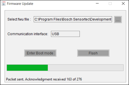
Figure 9 : Firmware upgrade completion
- Once firmware upgrade is complete, restart the application board, and DD2.0 UI.
Working with Development Desktop 2.0 – BMX055 sensor
Development Desktop 2.0 offers complete access to BMX055 sensor.
Sensor Data and Interrupts Monitoring
BMX055 sensor compromises of Accelerometer, Gyroscope and Magnetometer in a single package and the acceleration, gyro and magnetic field sensor signals can be monitored.
Accelerometer
This panel plots real time sensor signals from the accelerometer on the graph. The sensor data can be analyzed by using graph features like Play/Pause, view history, graph speed, Zoom In/Out, Zoom particular area in the graph, save and print current instance.
The accelerometer data can be represented in following units
- LSB : Raw acceleration signals read from sensors Data x, Data y and Data z registers
- m/s2 : Acceleration signals from sensor converted to meter per second square
- g : Acceleration signals from sensor in gravity unit.
To view this panel, click on Panels in the main menu and select Accelerometer. Alternately, Ctrl + A can be used as a shortcut
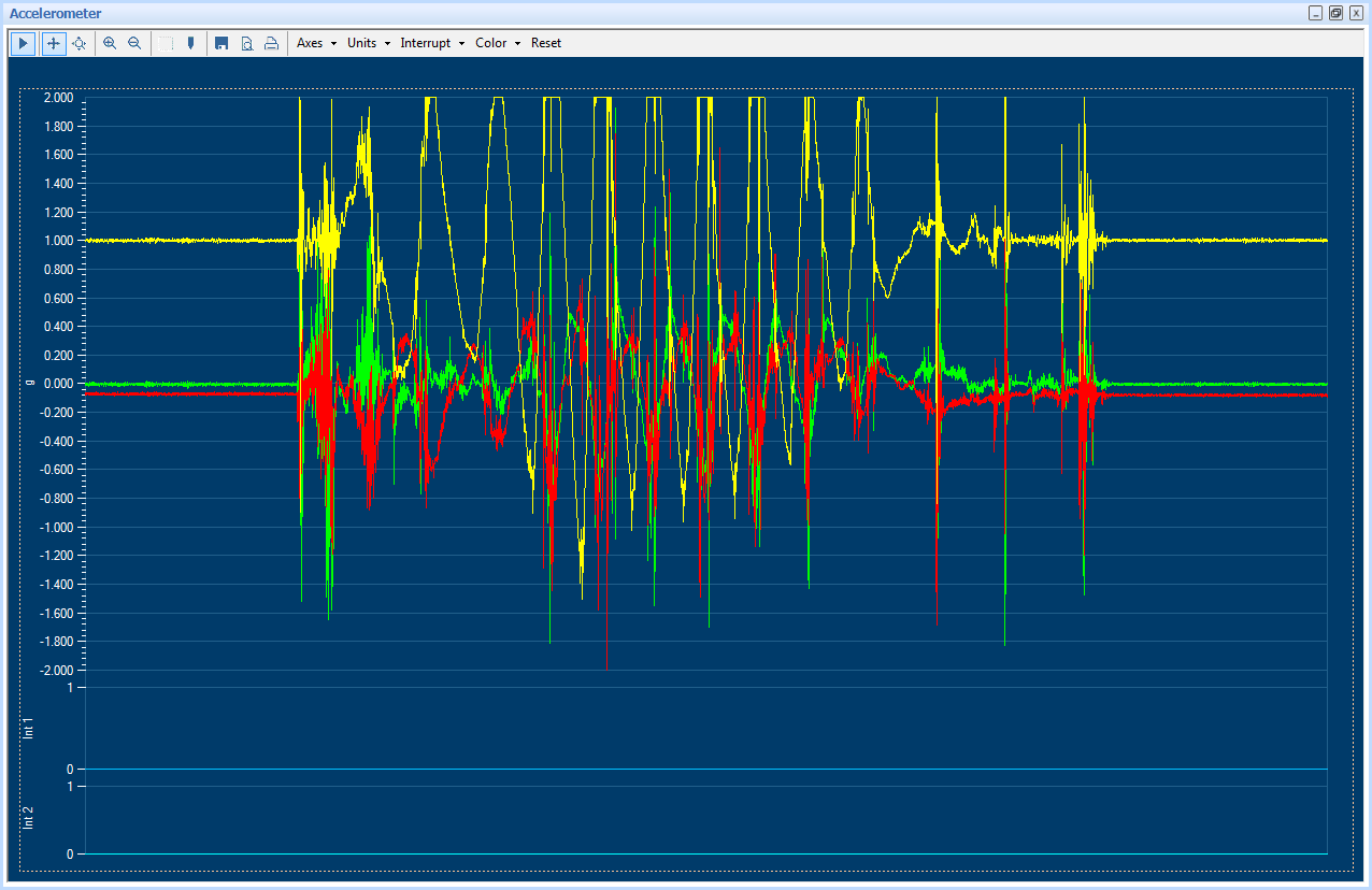
Figure 10 : Accelerometer plotter
Accelerometer Interrupts
This view shows the real time interrupt status of the accelerometer of the BMX055 sensor. The accelerometer has two interrupt lines where any interrupt can be latched. The round LEDs are the sensor interrupt status and the square LEDs are the interrupt pin status. The Interrupt occurrence can be visualized by the LED status to green.
To view this panel, click on Panels in the main menu and select Accel Interrupts. Alternately, Alt + A can be used as a shortcut.
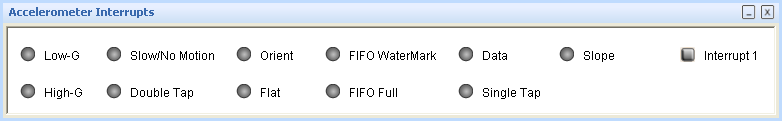
Figure 11 Interrupt View
Gyroscope
This panel plots real time sensor signals from the gyro on the graph. The sensor data can be analyzed by using graph features like Play/Pause, view history, graph speed, Zoom In/Out, Zoom particular area in the graph, save and print current instance.
To view this panel, click on Panels in the main menu and select Gyro. Alternately, Ctrl+Alt+G can be used as a shortcut.
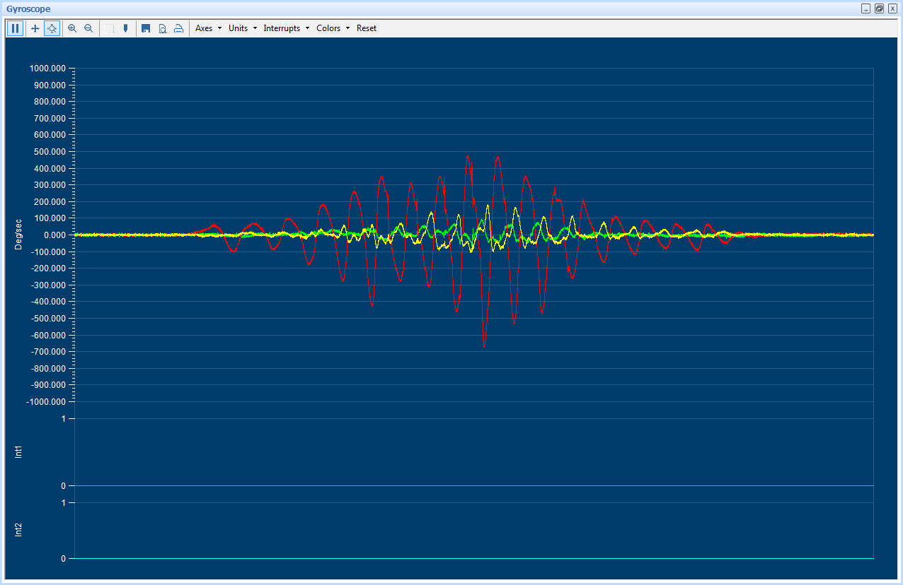
Figure 12 Gyroscope Plotter
Gyro Interrupts
This view shows the real time interrupt status of the accelerometer of the BMX055 sensor. The accelerometer has two interrupt lines where any interrupt can be latched. The round LEDs are the sensor interrupt status and the square LEDs are the interrupt pin status. The Interrupt occurrence can be visualized by the LED status to green.
To view this panel, click on Panels in the main menu and select Gyro Interrupts. Alternately, Alt + G can be used as a shortcut.
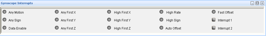
Figure 13 Gyroscope Interrupts
Magnetometer
This panel plots real time sensor signals from the magnetometer on the graph. The sensor data can be analyzed by using graph features like Play/Pause, view history, graph speed, Zoom In/Out, Zoom particular area in the graph, save and print current instance.
The magnetometer data can be represented in following units
- Raw : Raw magnetometer signals read from sensors Data x, Data y and Data z registers
- LSB : Compensated magnetic field strength in integer format as delivered by the API
- µT: Magnetic field strength signal represented in µT.
To view this panel, click on Panels in the main menu and select Magnetometer Alternately, Ctrl + M can be used as a shortcut.
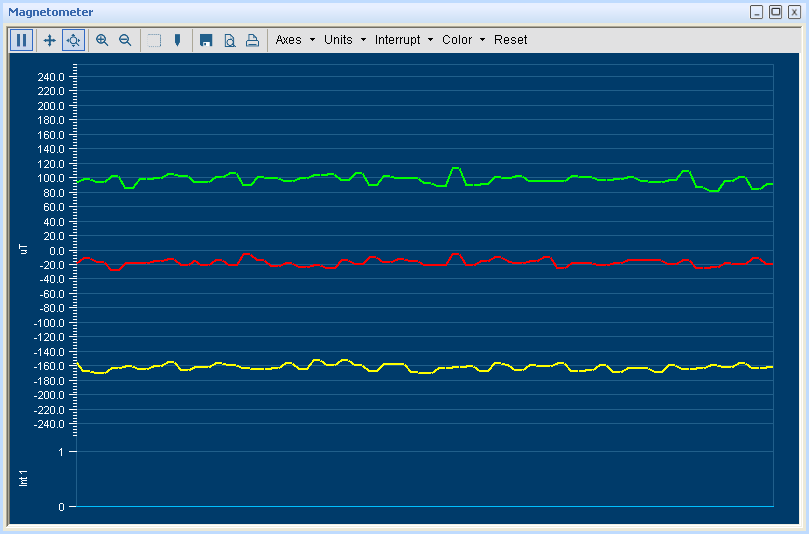
Figure 14 Magnetometer Plotter
Magnetometer Interrupts
This view shows the real time interrupt status from the magnetometer part of the BMM150 sensor. The magnetometer has one interrupt line. The LEDs are the sensor interrupt status and the square LEDs are the interrupt pin status. The Interrupt occurrence can be visualized by the LED status to green
To view this panel, click on Panels in the main menu and select Mag Interrupts Alternately, Alt + M can be used as a shortcut.
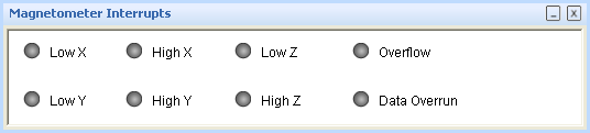
Figure 15 Magnetometer Interrupt
Data Export
The sensor signals are logged to a file by using the option Data Export. Both accelerometer and magnetometer data can be logged to a file. At least, one axis and the corresponding at least one unit must be to enable data log. To launch this view, click on Panels in the main menu and select Data Export. Alternately, Alt + D can be used as a shortcut.
Follow these steps to carry out the data export:
- Launch Data Export from Panels and click on Select Destination button.
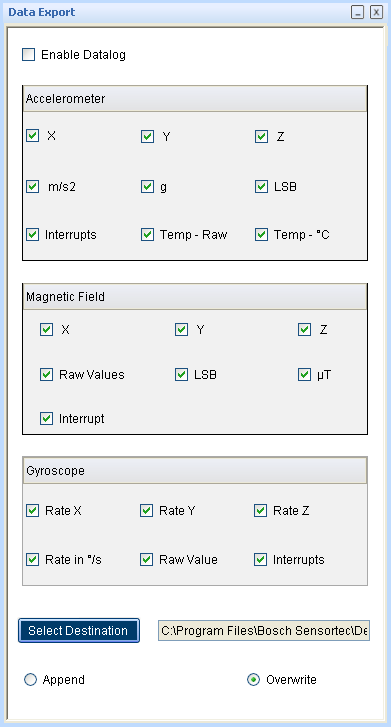
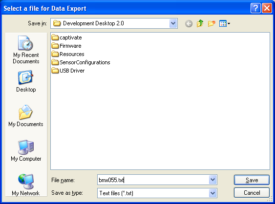
Figure 17 Data Export File Name
- Enable the axis data to be logged. Change the toggle button to append or overwrite. Then click OK. In Append mode, the new data is appended to the selected file. In Overwrite mode, the old data is erased from the selected file and the data from the new measurement is saved to it.
- Check the Enable Data Log check box.
- Click the Start button to plot acceleration signals in the graph. Click Stop to end the plotting of the acceleration signals in the graph. The output of the acceleration signals is saved in the desired destination path.BMA255 Sensor Configuration
The configurations can be classified as basic and advanced configuration. The entire basic configurations are available in the General Settings panel. The advance configuration can be accessed by various panels available under Memory Map and Register Access.
Selecting accelerometer Bandwidth
Two different streams of sensor data are available, unfiltered and filtered. The unfiltered data is sampled at 2 kHz. The sampling rate of the filtered data depends on the selected filter bandwidth and is always twice the selected bandwidth. The band width can be selected from Accelerometer settings in the General Settings panel. Use the Bandwidth
Selecting accelerometer Range
The accelerometer range setting configures the measurement range of the accelerometer sensor. The range can be selected to 2G, 4G, 8G or 16G from Accelerometer settings in the General Settings panel.
Selecting accelerometer Operation Mode
BMX055 accelerometer sensor can be configured to any one of the operation modes by selecting the options available in the drop down menu. The operation mode can be selected from Accelerometer settings in the General Settings panel
![]()
Note: For a detailed description of the sensors power saving modes and their applications, refer to the BMX055 sensor data sheet.
Reset sensor
This feature can be used to bring the sensor back to its default state. All the configuration data are reset to the default values. This is a soft reset and can be triggered for accelerometer and magnetometer separately. Sensor can be reset by the button click under General Setting panel.
Power – On reset
This is hard reset functionality. The VDD and VDDIO are turned OFF and then ON. This triggers the power-on- reset circuitry of the sensor. PO Reset button is available under General Setting panel.
Binary View
In the binary view, the sensor registers are identified by their addresses. The values displayed are the actual representation of the sensor memory map. This view is available for both accelerometer and magnetometer. If exact addresses of the sensor registers are known, this view can be helpful in writing direct values to the sensor memory map.
The value entered is converted to binary format and is displayed in the Binary text box.
- Click Write to transfer values to the actual registers.
- Click Read to read the current register setting of the sensor in the memory map window.
To launch this view, click on Panels in the main menu and select Memory Map -> Binary View. Alternately, Ctrl + B can be used as a shortcut.
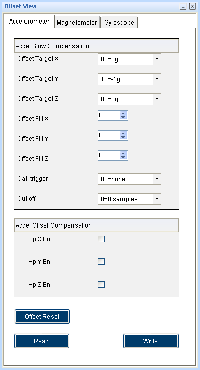
Offset View
The offset view provides a detail on slow compensation and offset compensation of accelerometer and can be controlled by this view. For information regarding the Offset view configuration of the Accelerometer sensor, refer to the corresponding user manual.
To launch this view, click on Panels in the main menu and select Memory Map -> Offset View. Alternately, Ctrl + O can be used as a shortcut
Interrupt configuration
The BMA255 is equipped with eight programmable interrupt engines. Each interrupt can be independently enabled and disabled. The BMA 255 provides two interrupt pins INT1 and INT2; interrupts can be freely mapped to any of these pins.
General feature
An interrupt is cleared depending on the selected interrupt modes which is common to all the interrupts. There are three different interrupt modes: non latched, latched and temporary. In non-latched mode the interrupt status bit and the selected pin is cleared as soon as activation condition is not valid. Exceptions to this behaviour are new data orientation and flat interrupts, which will automatically get reset after a fixed time. In latched mode the interrupt status bit and the selected pin are latched permanently. This will be cleared only on reset interrupt. In temporary mode an asserted interrupt status bit and the selected pin are cleared after a defined period of time.
It is strongly recommended to set the interrupt parameters prior to enabling the interrupt.
Changing the parameters of an already enabled interrupts may cause unwanted interrupt generation and generation of false interrupt history.
New data interrupt
This interrupt serves for synchronous reading of accelerometer data. It is generated after storing the new value of z-axis acceleration data in the data register. The interrupt is cleared automatically when the data acquisition starts.
The interrupt can be enabled by going to panels-> memory map->interrupt view and clicking on the data. If it needs to be mapped with the two interrupt pins INT1 and INT2 click on int1 and int2.
Slope / any motion detection
Slope / any motion detection use the slope between two successive acceleration values to detect the changes in motion. An interrupt is generated when the sloe exceeds a preset threshold. It is cleared soon as soon as the slope falls below the threshold. In order to suppress false triggers the interrupt is only generated (cleared) if a certain no N of consecutive slope data points is larger (small) than the threshold.
The interrupt can be enabled (disabled) for each axis by going to panels-> memory map->interrupt view and clicking on the Slope X, Y, Z. If it needs to be mapped with the two interrupt pins INT1 and INT2 click on int1 and int2.
Tap sensing
Tap sensing has a functionality similarity with a common laptop touch pad or clicking keys of a computer mouse. A tap event is detected if a predefined slope of the acceleration of at least one axis is exceeded. Two different tap events are distinguished. A single tap is a single event with a certain time, followed by a certain quiet time. A double tap consist of first such event followed by a second event with in a defined time frame.
Orientation recognition
The orientation recognition feature, informs the orientation change of the sensor with respect to the gravitational field vector ’g’. Orient can be enabled by clicking on orient in panels-> memory map->interrupt view-
>Interrupt mapping. It can be mapped with the two interrupt pins INT1 and INT2 by clicking onint1 and int2.
Flat detection
The flat detection feature gives information about the orient of the devices z- axis relative to the g-vector i.e. it recognizes whether the device is in flat position or not. The flat interrupt will occur when the device is in flat position and it will get cleared automatically after one sample period.
Low-g interrupt
This interrupt is based on the comparison of acceleration data against a low-g threshold, which is most useful for free fall detection. The low G threshold is set through the selection box threshold in low-g settings. The duration can be set. Mode can be ‘sum’ mode or ‘single’ mode and hysteresis.
High-G interrupt
This interrupt is based on the comparison of acceleration data against a high–g threshold for the detection of shock or other high-acceleration events. The high G threshold is set through the selection box threshold in high-g settings. The high-g duration can be also set through duration.
No motion/ slow motion detection
No motion/ slow motion detection interrupt engine can be configured in two modes. In slow motion mode an interrupt is triggered when the measured slope of at least one enabled axis exceeds the programmable slope
threshold for a programmable no of samples. In no-motion mode an interrupt is generated if the slope on all selected axis remains smaller than a programmable threshold for programmable delay time. After selecting all these write image need to be clicked.
Trim Registers
To launch this view, click on Panels in the main menu and select Memory Map -> Trim registers. Alternately, Ctrl + T can be used as a shortcut. To configure these registers, extended memory map should be enabled by checking Enable extended memory map checkbox. By enabling the extended memory map the stored and calculate CRC will be displayed. After making the changes to the register click on the write button to reflect in the sensor. Click on the read button to get the updated CRC.
FIFO Operation modes
The BMA255 features an integrated FIFO memory capable of storing 32 frames. Conceptually each frame consists of x, y, z axis which are sampled at same point in time.
FIFO can be operated in three modes.
- BYPASS mode
- FIFO mode
- STREAM mode
BMG160 Sensor Configuration
The configurations can be classified as basic and advanced configuration. The entire basic configurations are available in the General Settings panel. The advance configuration can be accessed by various panels available under Memory Map and Register Access. The sensor mode, bandwidth and range can be configured from the general settings.
Selecting the power mode
The BMG160 has four different power modes. Besides normal mode, which represents the fully operational state of the device, there are three energy saving modes: deep-suspend mode, suspend mode, and fast power up Sensor can be configured to any one of the modes can be selected from the scroll down menu.
After power-up BMG160 is in normal mode so that all parts of the device are held powered- up and data acquisition is performed continuously.
![]()
- In deep suspend mode the device reaches the lowest possible power consumption. Only the interface section is kept alive. No data acquisition is performed and the content of the configuration is lost.
- In suspend mode the complete analog part is powered down. No data acquisition is performed. While in suspend mode the latest angular rate data and the content of all configuration data are kept.
- In fast power up mode the sensing analog part is powered down, while the digital part remains purely operational. No data acquisition is performed.
- Using the mode option, mode of the sensor can be changed. The mode can be selected from the drop down list. By default, the Normal Mode is selected.
For a detailed description of the BMG160 power saving modes and their applications, refer to the BMG160 data sheet.
Selecting the band width
Two different streams of angular rate data are available, unfiltered and filtered. The unfiltered data is sampled at 2 kHz. The sampling rate of the filtered data depends on the selected filter bandwidth and is always twice the selected bandwidth.
The band width can be selected from general settings dropdown menu.
![]()
Selecting the range
The range can be selected from the drop down list. BMG160 supports five different measurement ranges.
- 2000o/s range
- 1200o/s range
- 500o/s range
- 250o/s range
- 125o/s range
![]()
Reset Sensor
A soft reset causes all user configuration settings to be overwritten with their default values and sensor enters to the normal mode.
Click the Reset button to soft reset the sensor.
Reset Interrupt
This will reset any active interrupt. The interrupt will again occur only if the interrupt is enabled and the particular interrupt condition occurs.
Binary View
In the binary view, the sensor registers are identified by their addresses. The values displayed are the actual representation of the sensor memory map. This view is available for both accelerometer and magnetometer. If exact addresses of the sensor registers are known, this view can be helpful in writing direct values to the sensor memory map. The value entered is converted to binary format and is displayed in the Binary text box.
- Click Write to transfer values to the actual registers.
- Click Read to read the current register setting of the sensor in the memory map window.
To launch this view, click on Panels in the main menu and select Memory Map -> Binary View. Alternately, Ctrl + B can be used as a shortcut.
OFFSET view
Offset in measured signals can have several causes but there are unwanted and disturbing in many cases. Therefore four digital compensation methods are offered. These are slow, fast and manual compensation as well as inline calibration. The compensation is performed with the filtered data, and is then applied to both, unfiltered and filtered data.
To launch this view, click on Panels in the main menu and select Memory Map -> Offset View. Alternately, Ctrl + O can be used as a shortcut. The OFFSET View can be selected by clicking on panels-> memory map-> OFFSET view.
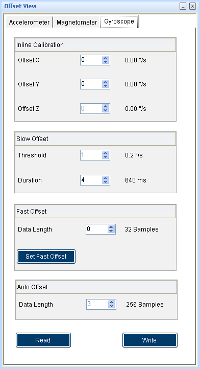
Figure 19 Offset View
Interrupt configuration
The BMG160 is equipped with three programmable interrupt engines. Each interrupt can be independently enabled and configured. The BMG160 provides two interrupt pins INT1 and INT2; interrupts can be freely mapped to any of these pins.
General features
An interrupt is cleared depending on the selected interrupt modes which is common to all the interrupts. There are three different interrupt modes: non latched, latched and temporary. In non-latched mode the interrupt status bit and the selected pin is cleared as soon as activation condition is not valid. Exceptions to this behaviour are new data orientation and flat interrupts, which will automatically get reset after a fixed time. In latched mode the interrupt status bit and the selected pin are latched permanently. This will be cleared only on reset interrupt. In temporary mode an asserted interrupt status bit and the selected pin are cleared after a defined period of time.
It is strongly recommended to set the interrupt parameters prior to enabling the interrupt. Changing the parameters of an already enabled interrupts may cause unwanted interrupt generation and generation of false interrupt history.
New data interrupt
This interrupt serves for synchronous reading of angular rate data. It is generated after storing the new value of z-axis angular rate data in the data register. The interrupt is cleared automatically when the data acquisition starts. The interrupt can be enabled by going to panels-> memory map->interrupt view and clicking on the data. If it needs to be mapped with the two interrupt pins INT1 and INT2 click on int1 and int2.
Any motion
Slope / any motion detection uses the slope between two successive angular rate signals to detect the changes in motion. An interrupt is generated when the slope exceeds a preset threshold. It is cleared soon as soon as the slope falls below the threshold. In order to suppress false triggers the interrupt is only generated (cleared) if a certain no N of consecutive slope data points is larger (small) than the threshold.
The interrupt can be enabled (disabled) for each axis by going to panels-> memory map->interrupt view and click on the Slope X, Y, Z. If it needs to be mapped with the two interrupt pins INT1 and INT2 click on int1 and int2.
The threshold can be selected from the panels-> memory map->interrupt view ->Any motion slope settings -> threshold. Slope samples and awake duration can be set through the respective text boxes in Any motion settings.
High- rate interrupt
- This interrupt is based on the comparison of angular rate data against a high angular rate threshold for the detection of shock or other high- angular rate events.
- The interrupt can be enabled or disabled by going to panels-> memory map->interrupt view->Interrupt mapping and by clicking on high rate. Each axis can be enabled by clicking on X,Y,Z.
- The high Rate threshold is set for each axis through the selection box threshold in High- Rate X-axis, Y-axis and Z-axis settings. The High-Rate duration can be also set through duration time. The high Rate threshold hysteresis can be set through threshold hysteresis text box. After selecting all these write image need to be clicked.
FIFO view
FIFO Operation modes: The BMG160 features an integrated FIFO memory capable of storing 100 frames. Conceptually each frame consists of x, y, z axis which are sampled at same point in time. FIFO can be operated in three modes.
- BYPASS mode
- FIFO mode
- STREAM mode
Register Access
This view provides direct access to the sensor registers. If the correct register address of the sensor memory map is know, this view can be very useful. The values can be read from or can be written to the sensor register.
To launch this view, click on Panels in the main menu and select Register Access. Alternately, Ctrl + R can be used as a shortcut. Select the accelerometer for accelerometer register access. Click on gyro meter for gyro meter register access.
BMM150 Sensor Configuration
The configurations can be classified as basic and advanced configuration. The entire basic configurations are available in the General Settings panel. The advance configuration can be accessed by various panels available under Memory Map and Register Access.
Selecting magnetometer Operation Mode
Using the operational mode option, measurement samples of the sensor can be controlled. The mode ranges can be selected from the drop down list. The operation mode can be selected from Magnetometer settings in the General Settings panel. By default, the Custom Mode is selected.
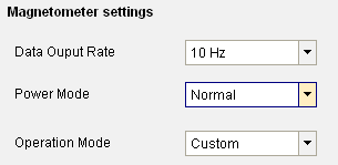
Figure 20 Magnetometer Operation Mode
- Low power mode:
- 10 Hz data rate
- Low power consumption
- Regular Mode:
- 10 Hz data rate
- Low noise
▶ Enhanced Regular Mode:
- 10 Hz data rate
- Lowest possible noise
▶ High Accuracy Mode:
- 20 Hz data rate
- Highest Accuracy Lowest possible noise
Reset sensor
This feature can be used to bring the sensor back to its default state. All the configuration data are reset to the default values. Sensor can be reset by the button click under General Settings panel.
Power – On reset
This is hard reset functionality. The VDD and VDDIO are turned OFF and then ON. This triggers the power-on- reset circuitry of the sensor. PO Reset button is available under General Settings panel.
Binary View
In the binary view, the sensor registers are identified by their addresses. The values displayed are the actual representation of the sensor memory map. If exact addresses of the sensor registers are known, this view can be helpful in writing direct values to the sensor memory map.
The value entered is converted to binary format and is displayed in the Binary text box.
- Click Write to transfer values to the actual registers.
- Click Read to read the current register setting of the sensor in the memory map window.
To launch this view, click on Panels in the main menu and select Memory Map -> Binary View or Press Ctrl + B
Offset View
The offset view provides a detail on magnetometer’s trimming values. The Magnetometer Trimming values displayed are taken up for calculating the offset for the magnetometer.
To launch this view, click on Panels in the main menu and select Memory Map -> Offset View. Or Press Ctrl
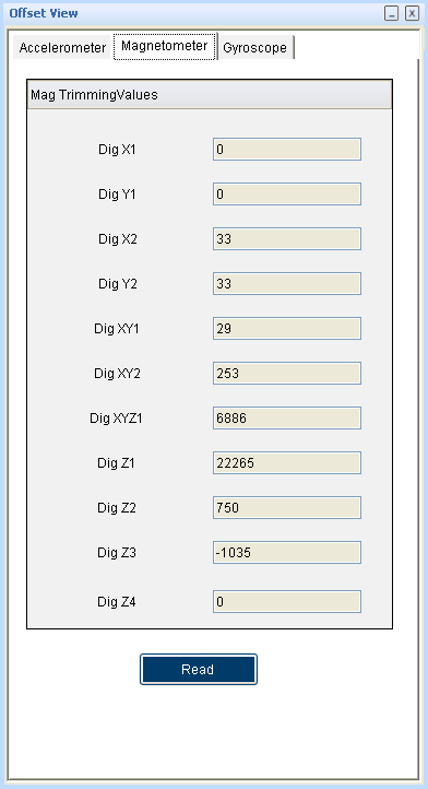
Figure 21 Offset View
Interrupt configuration
BMM150 sensor provides INT1 for magnetometer. The sensor interrupts can be independently enabled or disabled and can be freely mapped to interrupt pin. To launch this view, click on Panels in the main menu and select Memory Map -> Interrupt View Or Press
Enable Interrupt Pin
Enable interrupt works based on the pin out from the sensor. If the interrupt pin is enabled and if, an interrupt occurs, this pin will go high and will remain high until interrupt is cleared. When this interrupt pin is disabled, even if any interrupt occurs it will not go high. Note: The interrupt pin is high-Z when disabled as it does not have a defined voltage level.
Overflow Interrupt
If overflow interrupt is enabled, and if, any of the X, Y and Z values exceeds the maximum value, then an interrupt is generated and the interrupt indicator turns green.
Enabling Low/High level IRQs
BMM150 provides two interrupts for the magnetic part: low level and high level IRQs. Low level and high level IRQs can be activated separately for each magnetic axis of BMM150 by checking the corresponding checkboxes.
Setting thresholds
Low level IRQ is issued when one of the activated axes (logic OR) is less than the value set in Threshold Low field. High level IRQ is issued when one of the activated axes (logic OR) exceeds the value set in Threshold High field.
Note: Both Threshold Low and Threshold High are expressed in “μT” units. However, the internal interrupt engine only compares the uncompensated ADC values to the selected threshold. This means that the accuracy of the setting is limited.
Latch IRQ
Checking the Latch IRQ checkbox enables IRQ latching, which means that the interrupt pin stays high after an interrupt event until the interrupt status register is read. After reading, the register is cleared. If latching is disabled, the interrupt status register will always reflect the result of the last measurement and retain its value until the next measurement is finished.
Magnetic sensor IRQ status display
The MAG interrupts tab shows the status of the magnetic interrupts of BMM150 and the status of the IRQ pin.
Register Access
This view provides direct access to the sensor registers. If the correct register address of the sensor memory map is know, this view can be very useful. The values can be read from or can be written to the sensor register.
To launch this view, click on Panels in the main menu and select Register Access Or Press Ctrl + R
Self Test
The Self Test menu permits to check the sensor functionality by applying electrostatic forces to the sensor core instead of external accelerations.
The Self Test View can be selected by clicking on panels-> memory map-> Self Test view. The self test is activated individually for each axis by selecting each axis from the drop down list. The direction of excitation can be chosen by clicking self-test sign from the drop down menu.
The Self Test menu enables access to the self test features of the magnetic sensor.
During normal self-test, the following processes are executed
- FlipCore signal path is verified by generating signals on-chip. These are processed through the signal path and the measurement result is compared to known thresholds.
- FlipCore (X and Y) bondwires to ASIC are checked for connectivity.
- FlipCore (X and Y) bondwires and MEMS are checked for shorting.
- Hall sensor connectivity is checked for open and shorted connections.
- Hall sensor signal path and hall sensor element offset are checked for overflow.
The sensor features an internal coil-on-chip advance self test mode. Advanced self test can be performed only for z axis.
Click the Adv Self Test button to display the result of the advanced self test. The value indicated after the advanced self test should be around 200 µT.
Legal disclaimer
Engineering samples
Engineering Samples are marked with an asterisk (*) or (e). Samples may vary from the valid technical specifications of the product series contained in this data sheet. They are therefore not intended or fit for resale to third parties or for use in end products. Their sole purpose is internal client testing. The testing of an engineering sample may in no way replace the testing of a product series. Bosch Sensortec assumes no liability for the use of engineering samples. The Purchaser shall indemnify Bosch Sensortec from all claims arising from the use of engineering samples.
Product use
Bosch Sensortec products are developed for the consumer goods industry. They may only be used within the parameters of this product data sheet. They are not fit for use in life-sustaining or safety-critical systems. Safety- critical systems are those for which a malfunction is expected to lead to bodily harm, death or severe property damage. In addition, they shall not be used directly or indirectly for military purposes (including but not limited to nuclear, chemical or biological proliferation of weapons or development of missile technology), nuclear power, deep sea or space applications (including but not limited to satellite technology).
The resale and/or use of Bosch Sensortec products are at the purchaser ’s own risk and his own responsibility. The examination of fitness for the intended use is the sole responsibility of the purchaser.
The purchaser shall indemnify Bosch Sensortec from all third party claims arising from any product use not covered by the parameters of this product data sheet or not approved by Bosch Sensortec and reimburse Bosch Sensortec for all costs in connection with such claims.
The purchaser accepts the responsibility to monitor the market for the purchased products, particularly with regard to product safety, and to inform Bosch Sensortec without delay of all safety-critical incidents.
Application examples and hints
With respect to any examples or hints given herein, any typical values stated herein and/or any information regarding the application of the device, Bosch Sensortec hereby disclaims any and all warranties and liabilities of any kind, including without limitation warranties of non-infringement of intellectual property rights or copyrights of any third party. The information given in this document shall in no event be regarded as a guarantee of conditions or characteristics. They are provided for illustrative purposes only and no evaluation regarding infringement of intellectual property rights or copyrights or regarding functionality, performance or error has been made.
Document history and modification
|
Rev. No |
Chapter |
Description of modification/changes |
Date |
|
1.0 |
BMX055 User Manual |
Initial release |
December 2012 |
|
1.1 |
BMX055 User Manual |
Adopt New Format |
August 2020 |
BOSCH BMX055 Desktop Development 2.0 User Manual – BOSCH BMX055 Desktop Development 2.0 User Manual –
[xyz-ips snippet=”download-snippet”]