BOSCH Built-in Oven Instruction Manual
Important Information – Fig.1
- The safe operation of this appliance can only be guaranteed if it has been installed to a professional standard in accordance with these installation instructions. The installer shall be liable for any damage resulting from incorrect installation.
- Check the appliance for damage after unpacking it. Do not connect the appliance if it has been damaged in transit.
- Proceed in accordance with the installation sheets for installing accessories.
- Before starting up the appliance, remove any packaging material and adhesive film from the cooking compartment and the door.
- Fitted units must be heat-resistant up to 90 °C, and adjacent unit fronts up to 65 °C.
- Do not install the appliance behind a decorative door or the door of a kitchen unit, as this may cause the appliance to overheat.
- Any cut-outs that need to be made in the units should be made before the appliance is installed. Remove any shavings, as they may prevent the electrical components from working properly.
- Wear protective gloves so that you do not cut yourself. Parts that are accessible during installation may have sharp edges.
- The mains socket for the appliance must either be located in the hatched area A or outside of the area where the appliance is installed.
- Secure any unsecured units to the wall using a standard bracket B.
- The dimensions in the figures are in mm.
Appliance under the worktop — Fig. 2
To ventilate the appliance, the intermediate floor must have a ventilation cut-out.
Secure the worktop to the fitted units. Proceed in accordance with the installation instructions for the hob.
Appliance in a tall unit – Fig. 3
To ventilate the appliance, the intermediate floors must have a ventilation cut-out.
If the tall unit has another back panel in addition to the element back panels, this must be removed.
Only fit the appliance up to a height which allows accessories to be easily removed.
Corner installation — Fig. 4
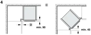
To ensure that the appliance door can be opened in a corner installation, take account of dimension C. Dimension D is dependent on the thickness of the unit front under the handle.
Connecting the appliance to the electricity supply
The appliance corresponds to protection class 1 and must only be operated with a protective earth connection.
The fuse protection must correspond to the power rating specified on the appliance’s rating plate and to local regulations.
The appliance must be disconnected from the power supply whenever installation work is being carried out. The appliance must only be connected with the power cable provided. Connect the power cable to the back of the appliance (listen for the click).
A 3 m power cable can be obtained from the after-sales service. The power cable must only be replaced with a cable from the original manufacturer, which can be obtained from the after-sales service.
When the appliance is installed, protection must be provided against accidental contact in the future.
Power cable with a plug with earthing contact
The appliance must only be connected to an earthing contact socket which has been correctly installed. If the plug can no longer be reached after the installation, a partition must be provided in the phases in the permanent electrical installation in accordance with the installation regulations.
Power cable without a plug with earthing contact
Only allow a licensed professional to connect the appliance. In the permanent electrical installation, an all-pole isolating switch must be provided in accordance with the installation regulations. Identify the phase and neutral conductors in the socket. The appliance may be damaged if it is not connected correctly. Only connect the hob according to the connection diagram. See the rating plate for the voltage. Connect the wires of the mains power cable according to the colour coding: Green/yellow = PE conductor $, blue = neutral conductor, brown = live (external conductor).
India only
Please note the different colour code for the wiring: Green/yellow = PE conductor ®, black = neutral conductor, red = live conductor (phase conductor).
Securing the appliance – Fig. 5
If your appliance has a pull-out carriage door, this must be removed beforehand.
- Slide the appliance all the way in and centre it.
- Screw the appliance into place. The gap between the worktop and appliance must not be sealed by additional strips. Thermal insulation strips must not be fitted to the side panels of the surround unit.
Removal
- Disconnect the appliance from the power supply.
- Undo the securing screws.
- Lift the appliance slightly and then pull it out completely.
[xyz-ips snippet=”download-snippet”]