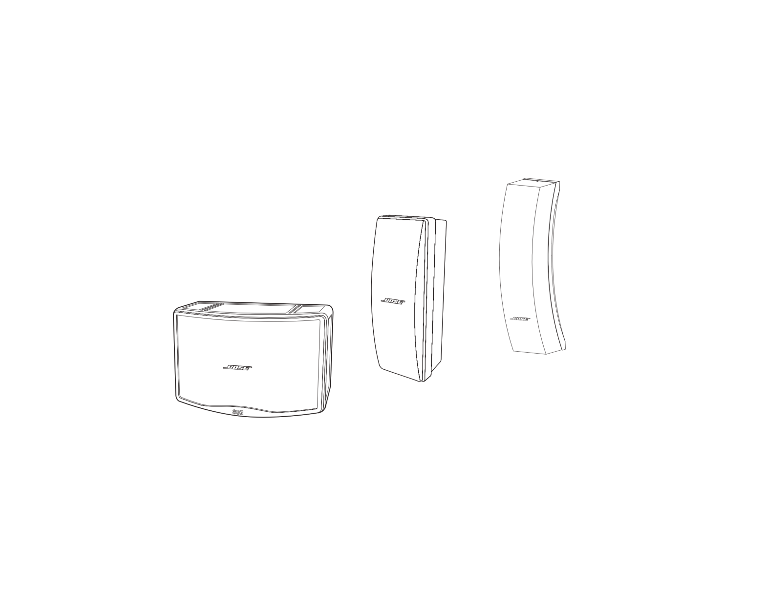
802 Series IV Modular Commercial Surface Mount Speaker
802® Series IV
402® Series IV
502®A
Panaray® Full-Range-Driver Array LoudspeakersInstallation Guide
Contents
pro.Bose.com
IntroductionOverview……………………………………………………………………………………………………………………………………………………………5 Panaray® 802® Series IV loudspeaker dimensions……………………………………………………………………………………………6 Panaray® 402® Series IV loudspeaker dimensions……………………………………………………………………………………………7 Panaray® 502® A loudspeaker dimensions………………………………………………………………………………………………………8InstallationPanaray® 802® Series IV loudspeaker mounting options ………………………………………………………………………………………….9 Panaray® 802® Series IV loudspeaker U-bracket……………………………………………………………………………………………..9 SB-8 suspension bracket …………………………………………………………………………………………………………………………..10WBP-8 wall bracket…………………………………………………………………………………………………………………………………………..11 Panaray® 402® Series IV loudspeaker mounting options ………………………………………………………………………………………..11RMUBRKT1 pan-and-tilt bracket kit…………………………………………………………………………………………………………….11 SB-4 suspension bracket kit……………………………………………………………………………………………………………………….13 Panaray® 502® A loudspeaker mounting options …………………………………………………………………………………………………..14 WCB-5 U-bracket kit …………………………………………………………………………………………………………………………………14 WBP-5 wall-mount kit………………………………………………………………………………………………………………………………..15 CVT-5 transformer kit ………………………………………………………………………………………………………………………………..15 CSB-5A suspension bracket kit…………………………………………………………………………………………………………………..17 Recommended power amplifiers ………………………………………………………………………………………………………………………..19 Recommended DSP settings ……………………………………………………………………………………………………………………………..19Technical InformationPanaray® 802® Series IV Loudspeaker Specifications ……………………………………………………………………………………………20 Panaray® 402® Series IV Loudspeaker Specifications ……………………………………………………………………………………………21 Panaray® 502®A Series Loudspeaker Specifications ……………………………………………………………………………………………..22Additional Resources
2
pro.Bose.com
Safety Information
Important Safety InstructionsThese loudspeakers are intended for installation by professional installers only! This document is intended to provide professional installers with basic installation and safety guidelines for loudspeakers in typical fixed-installation systems. Please read this document before attempting installation. WARNING: All Bose® products must be used in accordance with local, state, federal and industry regulations. It is the installer’s responsibility to ensure installation of the loudspeakers and mounting system is performed in accordance with all applicable codes, including local building codes and regulations. Consult the local authority having jurisdiction before installing this product. WARNING: Unsafe mounting or overhead suspension of any heavy load can result in serious injury and equipment damage. It is the responsibility of the installer to evaluate the reliability of any mounting method used for their application. Only professional installers with the knowledge of proper hardware and safe mounting techniques should attempt to install any loudspeaker overhead.Guidelines for permanent installation of Bose® Panaray® loudspeakersThe installation information contained in this document is only a general guideline and cannot, as such, represent all requirements and precautions. Accordingly, anyone using this material assumes all liability and is expressly responsible for the safety of all loudspeaker array designs and mounting configurations applied in practice. 1. Prior to the installation of any overhead loudspeaker, a licensed professional engineer must approve the location and method of attachment to the building structure and confirm theyare consistent with all building codes and regulations. Ensure the mounting surface and the method of attaching the loudspeaker system to the surface is capable of supporting the total weight of the system. A safety factor of 10:1 is recommended. 2. Obtain all mounting system components from reputable manufacturers. Select a mounting system appropriate for your loudspeaker system and its intended application. We recommend Bose mounting accessories when available. A licensed professional engineer must review the design and fabrication of any custom mounting hardware. 3. Bose Panaray loudspeakers feature integrated M8 threaded inserts to facilitate loudspeaker mounting by professional installers. Do NOT use SAE 5/16″ size threaded hardware! Use only metric hardware. Fasteners should be metric Class 8.8 (load bearing rated) or equivalent. Unmarked (not rated for load bearing) fasteners should not be used. 4. Use lock washers or a locking compound intended for hand disassembly, such as LOCTITE® THREADLOCKER BLUE 242® compound, for a vibration resistant assembly. 5. Fasteners should be tightened to the specified torque noted in the instructions. Over-tightening the fasteners could result in irreparable damage to the loudspeaker cabinet and create an unsafe assembly. 6. Do not attempt to alter the threaded attachment points or re-thread the attachment points to accommodate any other thread size or type; doing so will compromise the safety while permanently damaging the loudspeaker. 7. Use a safety cable, separately attached to the cabinet, at a point not in common with the load bearing attachment points of the mounting system to the loudspeaker. This is recommended even if not required by local regulation. Consult a licensed professional engineer or a rigging professional for proper design and installation.CAUTION: Installed loudspeakers require regular inspection and routine maintenance to ensure proper function and safe operation. Inspect mounting hardware and attachments for signs of corrosion, bending or any other condition that may decrease the structural integrity. Immediately replace worn or damaged components.CAUTION: Make no modifications to the loudspeakers or mounting accessories. Unauthorized alterations may compromise safety and could result in damage, injury, or death.This product conforms to all applicable EU directive requirements. The complete declaration of conformity can be found at www.Bose.com/compliance.
Información de seguridad importanteSolo un instalador profesional deberá instalar estos altavoces. Este documento ofrece a los instaladores profesionales instrucciones básicas de instalación y seguridad para altavoces en sistemas típicos de instalación fija. Lea este documento antes de intentar la instalación. ADVERTENCIA: Todos los productos Bose® deben utilizarse de acuerdo con las normas locales, estatales, federales e industriales. Será responsabilidad del instalador asegurarse de que la instalación de los altavoces y del sistema de montaje se realiza de acuerdo con todos los códigos aplicables, incluidos los códigos y normativas de construcción locales. Consulte a las autoridades locales pertinentes antes de instalar este producto. ADVERTENCIA: El montaje no seguro o la suspensión de cualquier carga pesada puede producir heridas graves y daños al equipo. Será responsabilidad del instalador evaluar la fiabilidad de cualquier método de montaje empleado en su aplicación. Sólo los instaladores profesionales con conocimiento de los accesorios adecuados y las técnicas de montaje seguro deberán intentar instalar cualquier altavoz en suspensión.Instrucciones para la instalación permanente de los altavoces Bose® Panaray®La información de instalación que contiene este documento ofrece sólo directrices generales y, por tanto, no puede representar todos los requisitos y precauciones. Por consiguiente, cualquiera que utilice este material asume expresamente toda la responsabilidad por la seguridad de todos los diseños de matriz de altavoces y de las configuraciones de montaje aplicadas en la práctica. 1. Antes de la instalación de cualquier altavoz en suspensión, un ingeniero profesional con licencia deberá aprobar la ubicación y el método de fijación a la estructura del edificio yconfirmar que cumplen todos los códigos y normativas de construcción. Compruebe que la superficie de montaje y el método para fijar el sistema de altavoces a la superficie son capaces de soportar el peso total del sistema. Se recomienda aplicar un factor de seguridad de 10:1. 2. Consiga todos los componentes de montaje de fabricantes de confianza. Seleccione un sistema de montaje adecuado para el sistema de altavoces y la aplicación a la que vayan destinados. Recomendamos utilizar accesorios de montaje Bose siempre que estén disponibles. Un ingeniero profesional con licencia deberá revisar el diseño y la fabricación de cualquier accesorio de montaje personalizado. 3. Los altavoces Bose Panaray incluyen piezas de ajuste roscadas M8 para facilitar el montaje del arreglo de altavoces a los instaladores profesionales. ¡NO utilice accesorios roscados SAE de 5/16″! Utilice únicamente accesorios métricos. Las abrazaderas deberán ser de Clase 8.8 métrica (destinadas a soportar carga) o equivalentes. No deberán emplearse abrazaderas sin marca (no destinadas a soportar carga). 4. Utilice arandelas de presión o un pegamento de fijación pensado para desmontaje manual, como LOCTITE® THREADLOCKER BLUE 242® , para conseguir un montaje resistente a vibraciones. 5. Las abrazaderas deberán apretarse con la torsión especificada en las instrucciones. Si se aprietan en exceso las abrazaderas, se podría causar un daño irreparable a la caja del altavoz y se crearía un ensamblado inseguro. 6. No intente alterar los puntos de fijación roscados ni volver a roscar los puntos de fijación para adaptarlos a otro tamaño o tipo de rosca; de hacerlo, comprometería la seguridad de la instalación, al tiempo que dañaría el altavoz de forma permanente. 7. Utilice un cable de seguridad, conectado a la caja por separado, en un punto distinto de los puntos de unión del sistema de montaje y el altavoz que sustenten la carga. Esta práctica se recomienda aunque no lo requiera la normativa local. Consulte a un ingeniero profesional con licencia o a un profesional de instalación para conocer el diseño y la instalación adecuados.PRECAUCIÓN: Los altavoces instalados requieren inspección periódica y mantenimiento rutinario para garantizar un funcionamiento correcto y seguro. Inspeccione en los accesorios y fijaciones de montaje si hay signos de corrosión, torceduras o cualquier otro problema que pueda reducir la integridad estructural. Sustituya inmediatamente los componentes desgastados o dañados.PRECAUCIÓN: No realice modificaciones en los altavoces o los accesorios de montaje. Las modificaciones no autorizadas pueden comprometer la seguridad y producir daños, lesiones o muerte.Este producto cumple todos los requisitos aplicables de las Directivas de la UE. Encontrará la declaración de conformidad completa en www.Bose.com/compliance.3
pro.Bose.com
Introduction
OverviewPanaray® sound-reinforcement loudspeakers feature full-range cone transducers in proprietary array configurations that provide exceptional reliability in adverse conditions, while delivering natural vocal clarity. For more than five decades, Bose has been improving the performance of full-range cone transducers to provide unmatched reliability, natural sound quality, and wide coverage patterns. Available in both point-source and column line array acoustic designs, Panaray loudspeakers cover a wide variety of installed-sound venues, for indoor or outdoor locations.
Panaray® 802® Series IV
Panaray® 402® Series IV
The 802 Series IV loudspeaker, now in it’s 4th generation, features 8 full-range drivers arranged in a proprietary Articulated Array® design, delivering extension down to 52 Hz and natural vocal clarity all in a small, lightweight and weather resistant enclosure.
The compact enclosure of the 402 Series IV contains 4 full-range drivers arrayed for increased vertical coverage control. Compared to the 802, the 402 delivers similar output level, but with tighter vertical coverage and less low-frequency response. For smaller venues requiring a high-value solution, a single 402 is capable of covering an entire listening area for accurate speech and music reproduction.
8 x 4.5-inch full-range cone drivers
4 x 4.5-inch full-range cone drivers
52 15 kHz frequency range
73 15 kHz frequency range
120° H x 100° V coverage pattern
120° H x 60° V coverage pattern
123 dB maximum peak SPL
119 dB maximum peak SPL
Indoor/Outdoor
Indoor/Outdoor
Panaray® 502® AThe Panaray 502 A features 5 full-range drivers that deliver the most consistent coverage pattern versus frequency within the Panaray line. The slightly curved, narrow enclosure has an elegant design that blends with any decor. For speech program material, a single loudspeaker can cover smaller venues. Use with full-range music program requires additional subwoofers.5 x 4.5-inch full-range cone drivers103 15 kHz frequency range120° H x 70° V coverage pattern117 dB maximum peak SPLIndoor use only
CAUTION: These loudspeakers are intended for installation by professional installers only.
5
IntroductionPanaray® 802® Series IV loudspeaker dimensionsTop View
pro.Bose.com
Front View
Right View
Back View
Bottom View
6
pro.Bose.comPanaray® 402® Series IV loudspeaker dimensionsTop View
Introduction
Left View
Front View
Right View
Back View
Bottom View
7
IntroductionPanaray® 502® A loudspeaker dimensionsTop View
pro.Bose.com
Back View8
Left View
pro.Bose.com
Installation
Panaray® 802® Series IV loudspeaker mounting optionsPanaray® 802® Series IV loudspeaker U-bracket (for indoor or outdoor use)The Bose® 802 Series IV loudspeaker can be mounted on a wall or ceiling using the U-bracket accessory kit (not included). Recommended Tools: 5 mm Allen wrenchCAUTION: 802 Series IV loudspeakers weigh 13.6 kg (30 lb). Use caution when lifting to avoid injury and/or damage to the loudspeaker. Do not rest loudspeakers on their grilles.1. Choose a mounting location that will safely support the weight (13.6 kg (30 lb)) of the loudspeaker. Refer to “Guidelines for permanent installation of Bose® Panaray® loudspeakers” on page 3.CAUTION: Choose a position and mounting method consistent with local building codes and regulations. Ensure the mounting surface and the method of attaching the loudspeaker to the surface is structurally capable of supporting the weight of the loudspeaker. A 10:1 safety weight ratio is recommended.2. Hold the U-bracket in the mounting location and mark the holes.
3. Drill four holes and mount the bracket using all four screws.4. Remove the backing from the foam tape and attach a bracket spacer to each side of the loudspeaker. Insert an M8 cap screw into the front hole on each side of the loudspeaker. Do not tighten.
9
Installation5. Place the loudspeaker on the bracket.
pro.Bose.com
6. Tilt the loudspeaker to the desired angle and insert the second M8 cap screw on each side of the loudspeaker.
Wall mount pitch angles
Ceiling mount pitch angles
5.6 Nm (50 in-lb)7. Using a 5 mm Allen wrench, tighten all four cap screws to 5.6 Newton-meters (50 inch-pounds). 8. Connect field wiring and test loudspeaker operation.SB-8 suspension bracket (for indoor use only)The SB-8 suspension bracket kit is used for suspension-mounting one 802 loudspeaker. The kit provides 0-45 deg pitch.
10
pro.Bose.comWBP-8 wall bracket (for indoor use only)
Installation
Panaray® 402® Series IV loudspeaker mounting optionsRMUBRKT1 and WBPWR-50 pan-and-tilt bracket kit
M8 x 20 mm (4) For Panaray® 402®loudspeakers
M8 x 45 mm (4) For otherloudspeakers
Flat washers (4)Note: The RMUBRKT1 pan-and-tilt bracket is intended for indoor use only. For outdoor applications, use the WBPWR-50 panand-tilt bracket 1. Remove the lower carriage bolt and separate the front and rear halves of the bracket. Note: To mount the loudspeaker horizontally, remove the speaker plate, rotate it 90 degrees, and reattach it.
Speaker plate
Lower carriage bolt
11
Installation
pro.Bose.com
2. Attach the bracket to the wall. Follow the instructions provided with the wall bracket.Choose a position and mounting method consistent with local building codes and regulations. Ensure the mounting surface and the method of attaching the loudspeaker to the surface is structurally capable of supporting the weight of the loudspeaker (7.3 kg (16 lb)). A 10:1 safety weight ratio is recommended.
3. Using the included T3 square drive, remove the plastic inserts on the rear panel of the loudspeaker and attach the bracket to loudspeaker using only the included M8 x 20 mm screws.M8 x 20 mm 13.6 16.3 Nm (10 12 ft-lb)4. Hang the loudspeaker on the wall-mounted half of the bracket and install the lower carriage bolt removed earlier.
12
pro.Bose.com5. Adjust the pitch and yaw using the specified tightening torque.11 Nm (8 ft-lb)30°
Installation
9 Nm (7 ft-lb)
25 Nm (18 ft-lb)
SB-4 suspension bracket kit (for indoor use only)
M8 x 16 mm (2) M8 (2)
Attach the bracket to the rear of the 402® loudspeaker. Choose a position and mounting method consistent with local building codes and regulations.M8 x 1.25 x 16 mm 2.3 2.8 Nm (20 25 in-lb)25° 30° 35° 40° 45°
13
Installation Panaray® 502® A loudspeaker mounting optionsWCB-5 U-bracket kit (for indoor use only)
pro.Bose.com
M8 x 12 mm (3)
(5)
M5 x 10 mm
M8 x 20 mm (2)
1. Choose a mounting location that will safely support the weight of the loudspeaker (6.8 kg (15 lb)). Refer to “Guidelines for permanent installation of Bose® Panaray® loudspeakers” on page 3.
CAUTION: Choose a position and mounting method consistent with local building codes and regulations. Ensure the mounting surface and the method of attaching the loudspeaker to the surface is structurally capable of supporting the weight of the loudspeaker (6.8 kg (15 lb)). A 10:1 safety weight ratio is recommended.
2. Hold the U-bracket in the mounting location to mark and drill the holes.Use at least three (3) of the five (5) holes in the center vertical row of the U-bracket to attach it to the wall. When mounting the bracket vertically, be sure to use the top center hole as one of the three.
rule on top3. Remove end screws and mount lock bracket.
M8 x 12 mm 2.3-2.8 Nm (20-15 in-lb)
Locking bracket
14
pro.Bose.com
Installation
4. Attach the 502® A loudspeaker to the U-bracket. Rotate the loudspeaker to the desired angle and insert the thumbscrew into the locking bracket.
MADE IN USA
PT143722
BOSE CORPORATION, FRAMINGHAM, MA 01701-9168
+ +
PARALLEL INPUT
S/N
DOM
FU SE
4A T
POW E R H A N D L IN 4G5 (0IEWCA()X)M
N O M IN A L IM P E D8A N C E
M U S T B E U S E D YSW TITECHOM 5NR0TO2 LCRLSE
R E FTEO ORW NR’ES M UAANL FR O PRO P E RTAINLATS IO N A N D O PRAET IN GROPC E DSU R E
Pa nrayTMSystem 5 0 TM2 AContro lle dArray
®
M8 x 20 mm5. Make sure the safety cable is installed.
M5 x 10 mm
Safety cableWBP-5 wall-mount kit (for indoor use only)M8 x 25 mm M6 x 25 mm M8 x 16 mm (5)1. Choose a mounting location that will safely support the weight of the loudspeaker (6.8 kg (15 lb)). Refer to “Guidelines for permanent installation of Bose® Panaray® loudspeakers” on page 3.CAUTION: Choose a position and mounting method consistent with local building codes and regulations. Ensure the mounting surface and the method of attaching the loudspeaker to the surface is structurally capable of supporting the weight of the loudspeaker. A 10:1 safety weight ratio is recommended.CVT-5 transformer kit (for indoor use only)
15
Installation2. Remove both screws from the bracket and separate the two pieces.
pro.Bose.com
3. Hold the wall bracket in the mounting location to mark and drill the holes. Use four (4) screws per bracket to attach it to the wall. The loudspeaker can be mounted vertically on a wall (A), angled down from a ceiling (B) or angled out from a wall (C).
A
B
C
4. Mount the speaker plate on the 502® A loudspeaker using four M8 x 16 mm screws.Rotate speaker plate 180° to mount as shown in Step 3A.M8 x 16 mm (4) 2.3 2.8 Nm (20 25 in-lb)16
pro.Bose.com
Installation
5. Mount the loudspeaker on the wall plate. Slide the fin of the speaker bracket into the wall bracket and install the M8 x 25 mm pivot screw, and then the M6 x 25 mm pitch locking screw.
M8 X 25 mm
M6 X 25 mm6. Set the pitch and yaw of the loudspeaker. To set the pitch: Loosen the M8 x 25 mm screw, remove the M6 x 25 mm screw, change the angle and re-insert the screw. Tighten both screws. To set the yaw: loosen both screws screw, change the angle and tighten both screws.
0° to 45°
±60°
M6 X 25 mm
M8 X 25 mm
7. Using an M8 x 16 mm screw, attach the safety cable to the speaker. Make sure the safety cable is attached to the wall independent of the wall plate.
CSB-5A suspension bracket kit (for indoor use only)M8 x 1.25 x 12 mm (3) (3)17
Installation1. Remove the screw from the end of the 502® A loudspeaker.2. Mount the bracket to the loudspeaker.M8 x 1.25 x 12 mm 2.3 2.8 Nm (20 25 in-lb)
pro.Bose.com
3. Choose a position and mounting method consistent with local building codes and regulations.
6.8 kg (15 lb)
Actual angles for 502 A with a constant voltage transformer
Bracket0° 5° 10° 15° 20° 25° 30° 35° 40° 45°
Actual angle0° 5° 10° 15° 20° 24° 27° 32° 37° 40°
18
pro.Bose.com
Installation
Recommended power amplifiersSelecting the proper amplifier size for a given loudspeaker requires analysis of the transducer long-term (or RMS) power rating, dynamic range of the input-source material (crest factor), desired sound pressure levels, and other factors. As a general guideline, the following table provides recommended power amplifier ranges for Bose® Panaray® loudspeakers:
Model
Nominal Impedance
Required Channels
Amp Power Rating
802® Series IV
250 500 Watts
402® Series IV
8 ohms
1
125 250 Watts
502® A
150 300 Watts
CAUTION: Failure to follow these guidelines may result in damage to the loudspeaker!Please refer to the specifications listed on the pro.Bose.com website for PowerMatch® amplifiers and compare with the table above to determine which PowerMatch model is best for your particular Panaray loudspeaker system design.
Recommended DSP settingsBose Panaray loudspeakers require active equalization for optimal sound quality. The recommended equalization is contained in the preset libraries of the Bose PowerMatch® configurable power amplifiers, ControlSpace® engineered sound and loudspeaker processors. EQ values can be downloaded using the Hardware Manager feature in ControlSpace DesignerTM software.The following table contains recommended loudspeaker parametric EQ values that have been confirmed with Bose ControlSpace Designer software and Bose Engineered Sound Processor (ESP) hardware. Results may vary with other brands of DSP hardware.Panaray 802 Series IV recommended EQ settings
Type Frequency Gain Bandwidth
Band 1PEQ 80 4.0 1.400
Band 2PEQ 160 4.0 1.200
Band 3PEQ 300 -4.5 1.000
Band 4PEQ 619 -5.7 1.500
Band 5PEQ 979 1.2 1.388
Band 6PEQ 1322 -5.6 1.000
Band 7PEQ 2845 -0.5 1.000
Band 8HiShelf 6200 5.2—
Band 9PEQ — — —
Panaray 402 Series IV recommended EQ settings
Type Frequency Gain Bandwidth
Band 1PEQ 100 2.0 1.000
Band 2PEQ 160 1.6 1.000
Band 3PEQ 500 -4.0 1.500
Band 4PEQ 1544 -5.2 1.500
Band 5PEQ 3390 -1.3 1.000
Band 6PEQ 6024 3.9 1.000
Band 7PEQ 120004.0 1.000
Band 8PEQ 144002.8 1.888
Band 9PEQ — — —
Panaray 502 A recommended EQ settings
Type Frequency Gain Bandwidth
Band 1PEQ 150 1.0 0.688
Band 2PEQ 206 -4.7 0.400
Band 3PEQ 338 -5.0 0.700
Band 4PEQ 655 -4.8 1.000
Band 5PEQ 1021 -1.4 1.018
Band 6PEQ 1367 -5.1 1.000
Band 7PEQ 4072 0.2 0.700
Band 8PEQ 6282 6.2 1.000
Band 9PEQ 123613.8 1.388
19
Technical Information
pro.Bose.com
Panaray® 802® Series IV Loudspeaker Specifications
Panaray® 802® Series IV
System Performance
Frequency Range (-10 dB)(1)
52 Hz 15 kHz
Recommended High-Pass Protection Filter
55 Hz with minimum 12 dB / octave filter
Nominal Coverage Pattern
120° H x 100° V
Loudspeaker EQ
active EQ required for optimal performance
Overload Protection
power limiting circuit (non-fused; automatic reset)
Bose extended-lifecycle test(2)
AES component test(3)
Power Handling, long-term continuous
240 W
300 W
Power Handling, peak
960 W
1200 W
Free field
Free field
Sensitivity (SPL / 1 W @ 1 m)(4)
92 dB
92 dB
Calculated Maximum SPL @ 1 m(5)
116
117
Calculated Maximum SPL @ 1 m, peak
122
123
Transducers
Full-range Drivers
8 x Bose 4.5-inch (114 mm) full-range cone transducers
Nominal Impedance
8 ohms
Physical
Enclosure Material
mineral-reinforced HDPE
Grille
power-coated steel grille
Environmental
outdoor per IEC 529 IP55
Connectors
2 x Neutrik® NL4 wired parallel
Suspension / Mounting
8 x M8 threaded inserts (2 back, 2 bottom, 4 sides)
Dimensions (H xW xD)
336 mm x 523 mm x 335 mm (13.2 x 20.6 x 13.2)
Net Weight
13.6 kg (30 lb)
Shipping Weight
17.2 kg (38 lb)
Product Code
Black
739058-0110
Notes:
1. Frequency range measured on-axis with recommended EQ in an anechoic environment.
2. Bose extended-lifecycle test: pink noise, IEC268-5 filtered, 6-dB crest factor, 100-hour duration, with recommended EQ.
3. AES component test: pink noise, IEC268-5 filtered, 6-dB crest factor, 2-hour duration, with recommended EQ.
4. Sensitivity measured in anechoic acoustic boundary conditions with recommended EQ, referenced to 1 W/m.
5. Maximum SPL calculated from sensitivity and power handling specifications, exclusive of power compression.
For additional specifications and application information, please visit pro.Bose.com. Specifications subject to change without notice.
20
pro.Bose.com
Technical Information
Panaray® 402® Series IV Loudspeaker Specifications
Panaray® 402® Series IV
System Performance
Frequency Range (-10 dB)(1)
73 Hz 15 kHz
Recommended High-Pass Protection Filter
75 Hz with minimum 12 dB / octave filter
Nominal Coverage Pattern
120° H x 60° V
Loudspeaker EQ
active EQ required for optimal performance
Overload Protection
power limiting circuit (non-fused; automatic reset)
Bose extended-lifecycle test(2)
AES component test(3)
Power Handling, long-term continuous
120 W
150 W
Power Handling, peak
480 W
600 W
Free field
Free field
Sensitivity (SPL / 1 W @ 1 m)(4)
91 dB
91 dB
Calculated Maximum SPL @ 1 m(5)
112
113
Calculated Maximum SPL @ 1 m, peak
118
119
Transducers
Full-range Drivers
4 x Bose 4.5-inch (114 mm) full-range cone transducers
Nominal Impedance
8 ohms
Physical
Enclosure Material
mineral-reinforced HDPE
Grille
power-coated steel grille
Environmental
outdoor per IEC 529 IP55
Connectors
2 x Neutrik® NL4 wired parallel
Suspension / Mounting
7 x M8 threaded inserts (4 back, 2 bottom, 1 top)
Dimensions (H xW xD)
592 mm x 206 mm x 202 mm (23.3 x 8.1 x 8.0)
Net Weight
7.3 kg (16 lb)
Shipping Weight
9.1 kg (20 lb)
Product Code
Black
739706-0110
White
739706-0210
Notes:
1. Frequency range measured on-axis with recommended EQ in an anechoic environment.
2. Bose extended-lifecycle test: pink noise, IEC268-5 filtered, 6-dB crest factor, 100-hour duration, with recommended EQ.
3. AES component test: pink noise, IEC268-5 filtered, 6-dB crest factor, 2-hour duration, with recommended EQ.
4. Sensitivity measured in anechoic acoustic boundary conditions with recommended EQ, referenced to 1 W/m.
5. Maximum SPL calculated from sensitivity and power handling specifications, exclusive of power compression.
For additional specifications and application information, please visit pro.Bose.com. Specifications subject to change without notice.
21
Technical Information
pro.Bose.com
Panaray® 502®A Series Loudspeaker Specifications
Panaray® 502A
System Performance
Frequency Range ± (-10 dB)(1)
103 Hz 15 kHz
Recommended High-Pass Protection Filter
110 Hz with minimum 12 dB / octave filter
Nominal Coverage Pattern
120° H x 70° V
Loudspeaker EQ
active EQ required for optimal performance
Overload Protection
fused: 4-ampere AGC 4 (Buss) or 3AG (Littlefuse)
Bose extended-lifecycle test(2)
AES component test(3)
Power Handling, long-term continuous
150 W
200 W
Power Handling, peak
600 W
800 W
Free field
Free field
Sensitivity (SPL / 1 W @ 1 m)(4)
88 dB
88 dB
Calculated Maximum SPL @ 1 m(5)
110
111
Calculated Maximum SPL @ 1 m, peak
116
117
Transducers
Full-range Drivers
5 x Bose 4.5-inch (114 mm) full-range cone transducers
Nominal Impedance
8 ohms
Physical
Enclosure Material
mineral-reinforced structural foam
Grille
power-coated steel grille
Environmental
indoor use only
Connectors
2 x Neutrik® NL4 and 2x barrier strips, wired parallel
Suspension / Mounting
4 x M8 threaded inserts (4 back)
Dimensions (H xW xD)
603 mm x 146 mm x 179 mm (23.8 x 5.8 x 7.1)
Net Weight
6.8 kg (15 lb)
Shipping Weight
8.3 kg (18 lb)
Product Code
Black
040170
White
040171
Notes:
1. Frequency range measured on-axis with recommended EQ in an anechoic environment.
2. Bose extended-lifecycle test: pink noise, IEC268-5 filtered, 6-dB crest factor, 100-hour duration, with recommended EQ.
3. AES component test: pink noise, IEC268-5 filtered, 6-dB crest factor, 2-hour duration, with recommended EQ.
4. Sensitivity measured in anechoic acoustic boundary conditions with recommended EQ, referenced to 1 W/m.
5. Maximum SPL calculated from sensitivity and power handling specifications, exclusive of power compression.
For additional specifications and application information, please visit pro.Bose.com. Specifications subject to change without notice.
22
pro.Bose.com
Additional Resources
Visit us on the web at pro.Bose.com for more information, including specifications, technical literature, product warranty, parts and accessories, and global support contact information.
Americas(USA, Canada, Mexico, Central America, South America) Bose Corporation The Mountain Framingham, MA 01701 USA Corporate Center: 508-879-7330 Americas Professional Systems, Technical Support: 800-994-2673AustraliaBose Pty Limited Unit 3/2 Holker Street Newington NSW Australia 61 2 8737 9999BelgiumBose N.V. / S.A Limesweg 2, 03700 Tongeren, Belgium 012-390800ChinaBose Electronics (Shanghai) Co Ltd 25F, L’Avenue 99 Xianxia Road Shanghai, P.R.C. 200051 China 86 21 6010 3800FranceBose S.A.S 12 rue de Temara 78100 St. Germain-en-Laye, France 01-30616363GermanyBose GmbH Max-Planck Strasse 36D 61381 Friedrichsdorf, Deutschland 06172-7104-0
Hong KongBose Limited Suites 2101-2105, Tower One, Times Square 1 Matheson Street, Causeway Bay, Hong Kong 852 2123 9000IndiaBose Corporation India Private Limited Salcon Aurum, 3rd Floor Plot No. 4, Jasola District Centre New Delhi 110025, India 91 11 43080200ItalyBose SpA Centro Leoni A Via G. Spadolini 5 20122 Milano, Italy 39-02-36704500JapanBose Kabushiki Kaisha Sumitomo Fudosan Shibuya Garden Tower 5F 16-17, Nanpeidai-cho Shibuya-Ku, Tokyo, 150-0036, Japan TEL 81-3-5489-0955 www.bose.co.jpThe NetherlandsBose BV Nijverheidstraat 8 1135 GE Edam, Nederland 0299-390139United KingdomBose Ltd 1 Ambley Green, Gillingham Business Park KENT ME8 0NJ Gillingham, England 0870-741-4500
See website for other countries
23
 report this ad
©2015 Bose Corporation, The Mountain Framingham, MA 01701-9168 USA AM747960 Rev.01
References
[xyz-ips snippet=”download-snippet”]