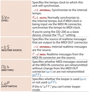
BOSS Digital Delay

Panel Descriptions
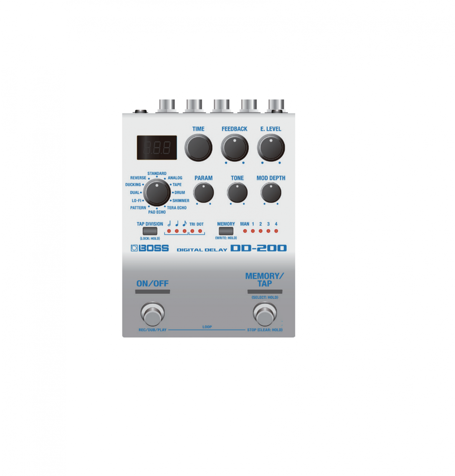
Top Panel

- DisplayShows the delay time, etc.
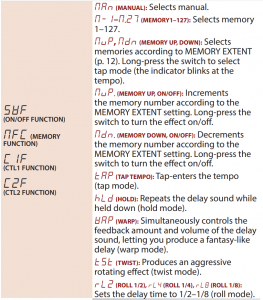
- [TIME] knobSets the delay time or switches memories.The display changes each time you press the knob.Example indicationsDelay time (time)
 Delay time (tempo)Memory
 - [FEEDBACK] knobAdjusts the amount of feedback (amount of repetition).* Depending on the sound that’s being input and on the position of the knob, oscillation might occur.
- [E.LEVEL] knobAdjusts the volume of the effect sound.If the mode is REVERSE, maximizing E.LEVEL cuts the direct sound.
- Mode knobSelects the delay mode.
Mode Explanation STANDARD Clear digital delay. ANALOG Mild analog delay. TAPE Sound with the distinctive waver of a tape echo unit. Models the Roland RE-201. DRUM Models the Binson EchoRec2. SHIMMER Delay that combines a pitch-shifted sound. TERA ECHO Echo sound that is neither reverb nor delay, with spaciousness and motion. PAD ECHO Delay sound with a drifting feel. PATTERN Sound that combines 16 delays. LO-FI Fat sound with a sense of distortion. DUAL Two delays connected in series. DUCKING The volume and feedback are automatically adjusted according to the input. Won’t get in the way of your performance even if applied deeply. REVERSE Delay that plays backward. - [PARAM] knobAdjusts an appropriate parameter for each mode.
Mode Explanation STANDARD Adjusts the sense of attack for the delay sound ANALOG Adjusts the character of the delay sound and the sense of distortion. TAPE Selects the combination of the three playback heads.If a decimal point “.” is shown for the lowest digit, distortion is added to the sound. DRUM Selects the combination of the four playback heads.If all of the playback heads are combined, the display indicates “ALL.”If a decimal point “.” is shown for the lowest digit, distortion is added to the sound. SHIMMER Adjusts the brilliance of the delay sound. TERA ECHO Adjusts the amount of distinctive character for the effect sound. PAD ECHO Selects the pattern of delays PATTERN Adjusts the sense of attack for the effect sound. LO-FI Adjusts the sense of distortion for the effect sound. DUAL Adjusts the second delay time. This is specified as a proportion (%) relative to the first delay. DUCKING Adjusts the sensitivity by which the volume is automatically adjusted according to the input. Increasing this value makes the response more sensitive at lower volumes. REVERSE Adjusts the sense of attack for the delay sound. - [TONE] knobAdjusts the tonal character of the effect sound.When the knob is in the center position, the response is flat. Turning the knob toward the right boosts the high frequency range, and turning it toward the left cuts the high-frequency range
- [MOD DEPTH] knobAdjusts the depth at which the effect sound is modulated.
- [TAP DIVISION] buttonSpecifies the delay time in terms of a note length relative to the BPM Preventing accidental operation (panel lock) By long-pressing the [TAP DIVISION] button, you can switch between enabling (unlocking) or disabling (locking) operation of the knobs and buttons.If you attempt an operation while the unit is locked, the display indicates “.”
- TAP DIVISION indicatorThis indicates the delay time as a note value; the interval at which you press the pedal is considered as a quarter note (100%)
TAP DIVISION indicator
Explanation
TRI DOT
✓
✓
Dotted half note (300%) ✓
Half note (200%) ✓
✓
Dotted quarter note (150%) ✓
✓
Half-note triplet (133%) ✓
Quarter note (100%) ✓
✓
Dotted eighth note (75%) ✓
✓
Quarter-note triplet (67% ✓
Eighth note (50%) ✓
✓
Eighth-note triplet (33%) - MEMORY] buttonSwitches or saves memories (MANUAL, 1–127) (Check down below). The memory is switched each time you press the [MEMORY] button. You can also switch memories by holding down the [MEMORY] button and turning the [TIME] knob.
- MEMORY indicatorIndicates the currently selected memory.If a memory 5–127 is selected, the indicator is unlit.
- [ON/OFF] switchTurns the delay on/off.
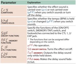
- [MEMORY/TAP] switchSwitches memories (Check down below).Long-press the [MEMORY/TAP] switch to select tap mode.By pressing the switch at the tempo of the song you’re performing, this lets you specify a matching delay time.MEMOThe function of the footswitch can be changed by (MEMORY FUNCTION).

Rear Panel (Connecting Your Equipment)
- To prevent malfunction and equipment failure, always turn down the volume, and turn off all the units before making any connections.

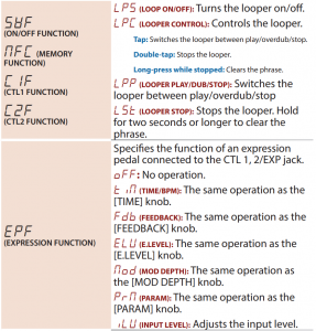
A. INPUT (A/MONO, B) jacksConnect your guitar, bass, or effect unit here.Use the A and B jacks if connecting an effect unit that has stereo output. Use only the A jack if using this unit in mono.Turning On/Off the PowerThe INPUT A jack also operates as the power switch. The power turns on when you insert a plug into the INPUT A jack.When powering upPower-up equipment such as your guitar amp last.When powering downPower-down equipment such as your guitar amp first.* Before turning the unit on/off, always be sure to turn the volume down. Even with the volume turned down, you might hear some sound when switching the unit on/off. However, this is normal and does not indicate a malfunction.B. OUTPUT (A/MONO, B) jacksConnect this jack to your amp or monitor speakers.Use only the OUTPUT A jack if using this unit in mono.Even sound that is input in stereo is output in mono.C. CTL 1, 2/EXP jackUsing the jack as CTL 1/2You can connect a footswitch (sold separately: FS-5U, FS-6, FS-7) and use it to tap-input the delay time or switch memories (Check down below).Using the jack as EXPYou can connect an expression pedal (sold separately: EV-30, Roland EV-5, etc.) and use it to control the delay time or the volume of the effect sound (Check down below).* Use only the specified expression pedal. By connecting any other expression pedals, you risk causing malfunction and/or damage to the unit.D. DC IN jack
An AC adaptor (sold separately: PSA-seriesS) can be connected to this jack.
- Use only the specified AC adaptor (sold separately: PSA-seriesS) and plug it into an AC outlet of the correct voltage.
- If the AC adaptor is connected while power is on, the power supply is drawn from the AC adaptor.
Side Panel (Connecting Your Equipment)

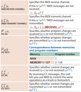
E. MIDI jacksUse a TRS/MIDI connecting cable (sold separately:BMIDI-5-35) to connect an external MIDI device. You can use an external MIDI device to switch the memories of this unit.* Do not connect an audio device here. Doing so will cause malfunctions.F. USB portConnect your computer using a commercially available USB cable that supports USB 2.0.
- Do not use a micro USB cable that is designed only for charging a device. Charge-only cables cannot transmit data.
- This is used only for program updates.
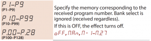
Saving and Switching Memories
Saving to Memory
Here’s how to save delay settings that you edited.
- Long-press the [MEMORY] button.The display indicates “Wrt.”
- Turn the [TIME] knob to select the save destination (MAN, 1–127).You can also select the save-destination by pressing the [MEMORY] button.If you decide to cancel, press the [TAP DIVISION] button.
- Long-press the [MEMORY] button to confirm the save-destination.The memory is saved.* If you save to MAN, the settings of the panel are applied as the values for MODE, FEEDBACK, E.LEVEL, PARAM, TONE, and MOD DEPTH.
Switching Memories
Here’s how to recall a saved memory.
- Press the [MEMORY] button to select a memory.Each time you press the button, you cycle through the memories in the order of “MAN (manual) → 1 → 2 → 3 → 4 …127 → MAN…”You can also switch memories by holding down the [MEMORY] button and turning the [TIME] knob.* The MEMORY indicator is unlit if a memory 5–127 is selected.MEMOYou can specify the memory switching range by editing the ETF (EXTENT FROM) and ETT (EXTENT TO) settings (Check down below).What is “MAN” (manual)?If you select “MAN,” the delay is heard using settings that reflect the actual positions of the knobs. The delay time and TAP DIVISION use the settings that you wrote into memory
Performing with Phrase Loops
You can use the looper to perform while recording and playing-back the sound in real time to create layers. This lets you layer sounds while applying delay
| Entering (exiting) looper mode: Press the [ON/OFF] switch and [MEMORY/TAP] switch simultaneously. When the looper starts, the display indicates “LoP.”
* Maximum recording time: approximately 60 seconds (mono) |
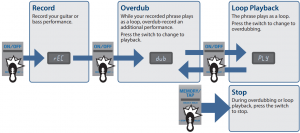
Clearing the phraseWhile stopped, hold down the [MEMORY/TAP] switch for two seconds or longer to clear (erase) the recorded phrase.
- When you exit looper mode, the recorded content is cleared.
- The recorded content is not saved.
* If there is recorded data, the ON/OFF indicator is lit. If there is no data, the indicator is unlit.
Basic Operation
- Press the [TAP DIVISION] button and [MEMORY] button simultaneously.You enter menu mode.
- Turn the [TIME] knob to select a parameter, and then press the [TIME] knob.The value is displayed.
- Turn the [TIME] knob to edit the value.
- Press the [TIME] knob.
- Press the [TAP DIVISION] button and [MEMORY] button simultaneously.You exit menu mode.
Assigning functions to external pedals
You can connect footswitches (sold separately: FS-5U, FS-6, FS-7) to the CTL 1, 2/EXP jack, and use them to tap-input the delay time or to switch memories.Use the menu items “C1F” or “C2F” to make these settings (Check down below).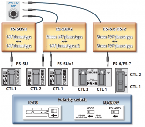

Appendix
Returning to the Factory Settings (Factory Reset)
Here’s how to return the DD-200 to its factory-set state.
- While holding down the [ON/OFF] switch and [MEMORY/TAP] switch, turn on the power (insert a plug into the INPUT A jack).The display indicates “FCt.”
- Press the [MEMORY/TAP] switch.The display indicates “Sur.”If you decide to cancel, press the [MEMORY] button.
- Press the [MEMORY/TAP] switch.The factory reset is executed.
- When the display indicates “FIn,” turn the power off and on again.
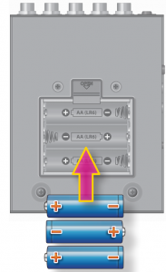
Installing Batteries
Insert the batteries as shown below, being careful to orient the batteries correctly.
- Batteries should always be installed or replaced before connecting any other devices. This way, you can prevent malfunction and damage.
- If operating this unit on batteries, please use alkaline batteries.
- Even if batteries are installed, the unit will turn off if you connect or disconnect the power cord from the AC outlet while the unit is turned on, or if you connect or disconnect the AC adaptor from the unit. When this occurs, unsaved data may be lost. You must turn off the power before you connect or disconnect the power cord or AC adaptor.
- When turning the unit over, be careful so as to protect the buttons and knobs from damage. Also, handle the unit carefully; do not drop it.
- If you handle batteries improperly, you risk explosion and fluid leakage.Make sure that you carefully observe all of the items related to batteries that are listed in “USING THE UNIT SAFELY” and “IMPORTANT NOTES” (leaflet “USING THE UNIT SAFELY” and Owner’s manual).
- “Lo” will appear on the display if the batteries are low. Replace them with new ones.
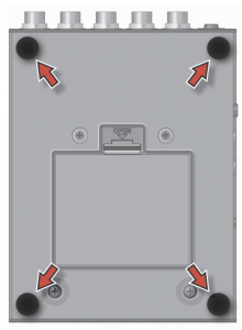
Attaching the Rubber Feet
You can attach the rubber feet (included) if necessary.Attach them in the locations shown in the illustration.
- Using the unit without rubber feet may damage the floor.
Main Specifications
BOSS DD-200: DIGITAL DELAY
| Power Supply | Alkaline battery (AA, LR6) x 3,AC adaptor (sold separately) |
| Current Draw | 225 mA |
| Expected Battery Life Under Continuous Use | Alkaline: Approx. 4 Hours
* These figures will vary depending on the actual conditions of use. |
| Dimensions | 101 (W) x 138 (D) x 63 (H) mm / 4 (W) x 5-7/16 (D) x 2-1/2 (H) inches101 (W) x 138 (D) x 65 (H) mm / 4 (W) x 5-7/16 (D) x 2-9/16 (H) inches (including rubber foot) |
| Weight | 680 g / 1 lb 8 oz (including batteries) |
| Accessories | Owner’s ManualLeaflet “USING THE UNIT SAFELY”Alkaline battery (AA, LR6) x 3Rubber foot x 4 |
| Options | AC adaptor: PSA-S seriesFootswitch: FS-5UDual footswitch: FS-6, FS-7Expression pedal: FV-500H, FV-500L, EV-30, Roland EV-5 MIDI/TRS connecting cable: BMIDI-5-35 |
* 0 dBu = 0.775 Vrms* This document explains the specifications of the product at the time that the document was issued. For the latest information, refer to the Roland website.
USING THE UNIT SAFELY/IMPORTANT NOTES
|
|
Keep small items out of the reach of children  To prevent accidental ingestion of the parts listed below, always keep them out of the reach of small children. To prevent accidental ingestion of the parts listed below, always keep them out of the reach of small children.
|
Repairs and Data
- Before sending the unit away for repairs, be sure to make a backup of the data stored within it; or you may prefer to write down the needed information. Although we will do our utmost to preserve the data stored in your unit when we carry out repairs, in some cases, such as when the memory section is physically damaged, restoration of the stored content may be impossible. Roland assumes no liability concerning the restoration of any stored content that has been lost.
Additional Precautions
- Any data stored within the unit can be lost as the result of equipment failure, incorrect operation, etc. To protect yourself against the irretrievable loss of data, try to make a habit of creating regular backups of the data you’ve stored in the unit.
- Roland assumes no liability concerning the restoration of any stored content that has been lost.
- Do not use connection cables that contain a built-in resistor.
Intellectual Property Right
- It is forbidden by law to make an audio recording, video recording, copy or revision of a third party’s copyrighted work (musical work, video work, broadcast, live performance, or other work), whether in whole or in part, and distribute, sell, lease, perform or broadcast it without the permission of the copyright owner.
- Do not use this product for purposes that could infringe on a copyright held by a third party. We assume no responsibility whatsoever with regard to any infringements of third-party copyrights arising through your use of this product.
- This product includes third party open source software.Copyright (c) 2009-2017 ARM Limited. All rights reserved. Licensed under the Apache License, Version 2.0 (the “License”); You may obtain a copy of the License at http://www.apache.org/licenses/LICENSE-2.0
- Roland, BOSS are either registered trademarks or trademarks of Roland Corporation in the United States and/or other countries.
- Company names and product names appearing in this document are registered trademarks or trademarks of their respective owners.
- In this manual, company names and product names of the respective owners are used because it is the most practical way of describing the sounds that are emulated using DSP technology

[xyz-ips snippet=”download-snippet”]