BOSS Graphic Equalizer
Before using this unit, carefully read “USING THE UNIT SAFELY” and “IMPORTANT NOTES” (the leaflet “USING THE UNIT SAFELY” and the Owner’s Manual (Check down below)). After reading, keep the document(s) where it will be available for immediate reference.
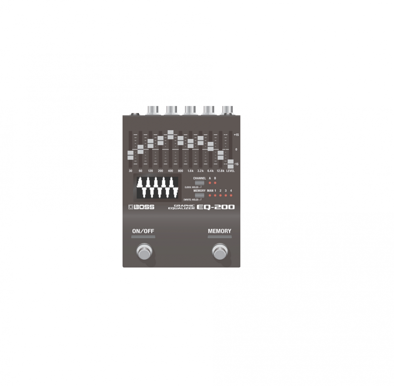
Panel Descriptions
Top Panel
- Graphic equalizerA ten-band graphic equalizer that provides ±15 dB of adjustment in the range of 30 Hz–12.8 kHz (the center frequency varies according to type).
- [LEVEL] sliderCompensates for the volume difference when switching between normal and effect sound.
- DisplayVisually indicates the state of the equalizer, or shows memory numbers or parameters.
- [CHANNEL] buttonSwitches the display between showing the states of channels A or B, or showing the memory number.Preventing accidental operation (panel lock)By long-pressing the [CHANNEL] button you can toggle between enabling operation of the equalizer and buttons (unlocked) or disabling operation (locked).If you operate the unit while it is locked, the display indicates “LOCKED.
- CHANNEL indicatorIndicates the currently selected channel.When the indicator is unlit, the display shows the memory number.* If the LINK parameter (p. 9) is ON, indicators A and B are both lit.
- [MEMORY] buttonSwitches or saves memories (MANUAL, 1–127) (Check down below).The memory is switched each time you press the[MEMORY] button.
- MEMORY indicatorIndicates the currently selected memory.If a memory 5–127 is selected, the indicator is unlit.
- [ON/OFF] switchSwitches the effect on/off.
- MEMORY] switchSwitches memories (Check down below).
MEMO
- The function of the footswitch can be changed by “SW FNC” (ON/OFF SW FUNCTION), “MEM FNC” (MEMORY SW FUNCTION).
- Regardless of the function of the footswitch, you can hold down the [MEMORY] button and press the [MEMORY] switch to increment the memory number or press the [ON/OFF] switch to decrement the memory number.
Rear Panel (Connecting Your Equipment)
- To prevent malfunction and equipment failure, always turn down the volume, and turn off all the units before making any connections.

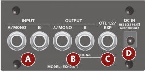
A. INPUT (A/MONO, B) jacks
Connect your guitar, bass, or effect unit here.Use the A and B jacks if connecting an effect unit thathas stereo output. Use only the A jack if using this unitin mono.
Turning On/Off the PowerThe INPUT A jack also operates as the power switch. The power turns on when you insert a plug into the INPUT A jack.
When powering upPower-up equipment such as your guitar amp last.When powering downPower-down equipment such as your guitar amp first.
- Before turning the unit on/off, always be sure to turn the volume down. Even with the volume turned down, you might hear some sound when switching the unit on/off. However, this is normal and does not indicate a malfunction.
B. OUTPUT (A/MONO, B) jacksConnect this jack to your amp or monitor speakers.Use only the OUTPUT A jack if using this unit in mono.Even sound that is input in stereo is output in mono.C. CTL 1, 2/EXP jackUsing the jack as CTL 1/2You can connect a footswitch (sold separately: FS-5U, FS-6, FS-7) and use it to switch memories or channels (Check down below)
Using the jack as EXPYou can connect an expression pedal (sold separately:EV-30, Roland EV-5, etc.) and use it to control the volume of the effect sound.
* Use only the specified expression pedal. By connecting any other expression pedals, you risk causing malfunction and/or damage to the unit.
D. DC IN jackAn AC adaptor (sold separately: PSA-S series) can be connected to this jack.
- Use only the specified AC adaptor (sold separately: PSA-S series) and plug it into an AC outlet of the correct voltage.
- If the AC adaptor is connected while power is on, the power supply is drawn from the AC adaptor.
Side Panel (Connecting Your Equipment)

E. MIDI jacksUse a TRS/MIDI connecting cable (sold separately:BMIDI-5-35) to connect an external MIDI device. You can use an external MIDI device to switch the memories of this unit.
- Do not connect an audio device here. Doing so will cause malfunctions.
F. USB portConnect your computer using a commercially available USB cable that supports USB 2.0.
- Do not use a micro USB cable that is designed only for charging a device. Charge-only cables cannot transmit data.
- This is used only for program updates.
Saving and Switching Memories
Saving to Memory
Here’s how to save equalizer settings that you edited.
- Long-press the [MEMORY] button.The display indicates “WRITE TO:.”
- Press the [MEMORY] switch or the [ON/ OFF] switch to select the save-destination (MAN, 1–127).You can also select the save-destination by pressing the [MEMORY] button.If you decide to cancel, press the [CHANNEL] button.
- Long-press the [MEMORY] button to confirm the save-destination.The memory is saved.
Switching Memories
Here’s how to recall a saved memory.
- Press the [MEMORY] button to select a memory.Each time you press the button, you cycle through the memories in the order of “MAN (manual) → 1 → 2 → 3→ 4 …127→ MAN…”You can also switch memories by holding down the [MEMORY] button and press the [MEMORY] or [ON/ OFF]switch.MEMOBy changing the EXT FROM (EXTENT FROM), EXT TO (EXTENT TO) settings (Check down below) you can specify the range within which memories are switched.
What is “MAN” (manual)?If STRUCT (STRUCTURE)=PARA and LINK=ON, selecting “MAN” applies the equalizer with settings that correspond to the position of the graphic equalizer’s sliders.For other settings, the settings saved in MAN are recalled.
Basic Operation
- Press the [CHANNEL] button and [MEMORY] button simultaneously.You enter menu mode.
- Press the [CHANNEL] button or [MEMORY] button to select a parameter.
- Press the [ON/OFF] switch or [MEMORY] switch to change the value.
- Press the [CHANNEL] button and [MEMORY] button simultaneously.You exit menu mode.
Assigning functions to external pedals
You can connect footswitches (sold separately: FS-5U, FS-6, FS-7) to the CTL 1, 2/EXP jack, and use them to switch memories or channels.Use the menu items “C1 FNC” or “C2 FNC” to make these settings (Check down below).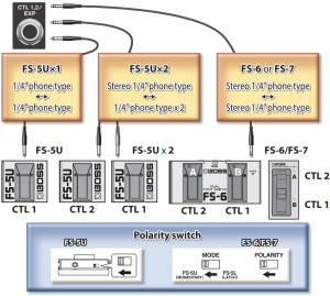
| Parameter | Explanation |
| SW FNC(ON/OFF FUNCTION)MEM FNC(MEMORY FUNCTION)C1 FNC(CTL1 FUNCTION)C2 FNC(CTL2 FUNCTION) | Specify the function of the [ON/OFF] switch, [MEMORY] switch, and the footswitches connected to the CTL 1, 2/ EXP jack.
* The functions that can be assigned differ depending on the switch. OFF: No operation.ON/OFF: Turn the equalizer on/off.M-UP (MEMORY UP),M-DN (MEMORY DOWN): Select a memory according to the MEMORY EXTENT (Check down below) setting.M-UP+ (MEMORY UP, ON/OFF),M-DN+ (MEMORY DOWN, ON/OFF): Select memories according to the MEMORY EXTENT (p. 9) settings. Long-press the switch to turn the effect on/off.MAN (MANUAL): Select manual.M1–127 (MEMORY 1–127): Select memories 1–127. |
| SW FNC(ON/OFF FUNCTION) MEM FNC(MEMORY FUNCTION)C1 FNC(CTL1 FUNCTION)C2 FNC(CTL2 FUNCTION | A, B (A, B ON/OFF): Turn channel A (or B) on/ off (if LINK is “ON,” turn A and B on/off simultaneously).A+, B+ (A, B ON/OFF+): Switch memories. Long-press the switch to turn channel A (or B) on/off (if LINK is “ON,” turn A and B on/off simultaneously). |
| EXP FNC(EXPRESSION FUNCTION) | Specifies the function of an expression pedal connected to the CTL 1, 2/EXP jack.A: Adjusts the level of channel A.B: Adjusts the level of channel B.TOTAL: Adjusts the overall output level. |
| EXP MIN(EXPRESSION MIN)EXP MAX(EXPRESSION MAX) | Specifies the variable range of the parameter controlled by EXPRESSION FUNCTION.0–100: Specify the minimum and maximum values |
| SW PREF(ON/OFF PREFERENCE) MEM PREF(MEMORY PREFERENCE) CTL1 PREF(CTL1 PREFERENCE)CTL2 PREF (CTL2 PREFERENCE)EXP PREF(EXPRESSION PREFERENCE) | MEM, SYS: Choose whether to use the settings of each memory or the settings common to the entire unit. |
| STRUCT (STRUCTURE) | Specifies how the A and B channel equalizers are connected.PARA (PARALLEL): INPUT/OUTPUT jacks A and B are connected to channels A and B respectively. SERIES: The A and B channel equalizers are connected in series. SERIES: The A and B channel equalizers are connected in series. The input is mixed to mono, and the same signal is output from A and B.For details, refer to “About STRUCT (STRUCTURE)” (Check down below). The input is mixed to mono, and the same signal is output from A and B.For details, refer to “About STRUCT (STRUCTURE)” (Check down below). |
| TYPE | Changes the center frequencies of the sliders.30.800.12K: 30/60/120/200/400/800/1.6k/ 3.2k/6.4k/12.8k (as printed on the panel)32/1k/16k: 32/63/125/250/500/1k/2k/4 k/8k/16k 28/880/14k: 28/55/110/220/440/880/1.75k/3.5k/7k/14k |
| LINK | Specifies whether the equalizer settings are shared by channels A and B.OFF: Channels A and B can be set independently.ON: Channels A and B use the same settings. |
| EXT FROM(MEMORY EXTENT FROM)EXT TO(MEMORY EXTENT TO) | Specifies the extent of memory switching (MEMORY EXTENT FROM–TO).MAN, M-1– |
| RX CH(MIDI RECEIVE CHANNEL) | Specifies the MIDI receive channel. If this is “OFF,” MIDI messages are not received.1–16, OFF |
| TX CH(MIDI TRANSMIT CHANNEL) | Specifies the MIDI transmit channel. If this is “OFF,” MIDI messages are not transmitted.1–16, RX (RECEIVE), OFF |
| PC IN | Specifies whether program changes are received (ON) or not received (OFF). |
| PC OUT | Specifies whether program changes are transmitted (ON) or not transmitted (OFF). |
| CC IN | Specifies whether control changes are received (ON) or not received (OFF). |
| CC OUT | Specifies whether control changes are transmitted (ON) or not transmitted (OFF). |
| SW CC(ON/OFF SW CC)MEM CC(MEMORY CC)CTL1 CCCTL2 CCEXP CC(EXPRESSION CC) | Specifies the controller number corresponding to each controller.OFF, 1–31, 64–95 |
| EFX SW CC | Directly turns the effect on/off. |
| MIDI THRU | Specifies whether MIDI messages received at the MIDI IN connector are retransmitted without change from the MIDI OUT connector (ON) or are not retransmitted (OFF). |
| CONTRAST | Adjusts the contrast of the display.1–10 |
| PC#1–128 | Specifies the memory that is selected by each incoming program change.OFF, MAN, M-1–127PC# transmitted from the EQ-200 |
| Memory | Program number |
| MAN | 1 |
| MEMORY 1–127 | 2–128 |
About STRUCT (STRUCTURE)
STRUCT (STRUCTURE)= PARA (PARARELL), LINK = ON
Operates as a stereo EQ.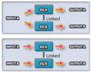
STRUCT (STRUCTURE)= PARA (PARARELL), LINK = OFF
Operates as two independent mono EQs.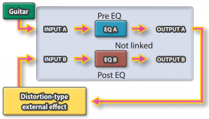
STRUCT (STRUCTURE) = SERIES
If you set the unit’s footswitch settings to A and B, it operates as two mono EQ units connected in series.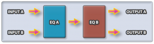
Appendix
Returning to the Factory Settings (Factory Reset)
Here’s how to return the EQ-200 to its factory-set state.
1. While holding down the [ON/OFF] switch and [MEMORY] switch, turn on the power (insert a plug into the INPUT A jack).The display indicates “FACTORY RESET.”2. Press the [MEMORY] switch.The display indicates “ARE YOU SURE?.”If you decide to cancel, press the [ON/OFF] switch.3. Press the [MEMORY] switch.The factory reset is executed.4. When the display indicates “COMPLETED,” turn the power off and on again.
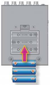
Installing Batteries
Insert the batteries as shown below, being careful to orient the batteries correctly.
- Batteries should always be installed or replaced before connecting any otherdevices. This way, you can prevent malfunction and damage.
- If operating this unit on batteries, please use alkaline batteries.
- Even if batteries are installed, the unit will turn off if you connect or disconnect the power cord from the AC outlet while the unit is turned on, or if you connect or disconnect the AC adaptor from the unit.When this occurs, unsaved data may be lost. You must turn off the power before you connect or disconnect the power cord or AC adaptor.
- When turning the unit over, be careful so as to protect the buttons and knobs from damage. Also, handle the unit carefully; do not drop it.
- If you handle batteries improperly, you risk explosion and fluid leakage.Make sure that you carefully observe all of the items related to batteriesthat are listed in “USING THE UNIT SAFELY” and “IMPORTANT NOTES”(leaflet “USING THE UNIT SAFELY” and Owner’s manual).
- “BATTERY LOW” will appear on the display if the batteries are low. Replace them with new ones.
Attaching the Rubber Feet
You can attach the rubber feet (included) if necessary.Attach them in the locations shown in the illustration.
- Using the unit without rubber feet may damage the floor.
Main Specifications
BOSS EQ-200: GRAPHIC EQUALIZER
| Power Supply | Alkaline battery (AA, LR6) x 3, AC adaptor (sold separately) |
| Current Draw | 170 mA |
| Expected Battery Life Under Continuous Use | Alkaline: Approx. 7 Hours
* These figures will vary depending on the actual conditions of use. |
| Dimensions | 101 (W) x 138 (D) x 60 (H) mm / 4 (W) x 5-7/16 (D) x 2-3/8 (H) inches101 (W) x 138 (D) x 62 (H) mm / 4 (W) x 5-7/16 (D) x 2-1/2 (H) inches (including rubber foot) |
| Weight | 700 g / 1 lb 9 oz (including batteries) |
| Accessories | Owner’s ManualLeaflet “USING THE UNIT SAFELY”Alkaline battery (AA, LR6) x 3Rubber foot x 4 |
| Options | AC adaptor: PSA-S seriesFootswitch: FS-5UDual footswitch: FS-6, FS-7 Expression pedal: FV-500H, FV-500L, EV-30, Roland EV-5MIDI/TRS connecting cable: BMIDI-5-35 |
* 0 dBu = 0.775 Vrms* This document explains the specifications of the product at the time that the document was issued. For the latest information, refer to the Roland website.
USING THE UNIT SAFELY/IMPORTANT NOTES
|
|
Keep small items out of the reach of children  To prevent accidental ingestion of the parts listed below, always keep them out of the reach of small children. To prevent accidental ingestion of the parts listed below, always keep them out of the reach of small children.
|
Repairs and Data
- Before sending the unit away for repairs, be sure to make a backup of the data stored within it; or you may prefer to write down the needed information. Although we will do our utmost to preserve the data stored in your unit when we carry out repairs, in some cases, such as when the memory section is physically damaged, restoration of the stored content may be impossible. Roland assumes no liability concerning the restoration of any stored content that has been lost.
Additional Precautions
- Any data stored within the unit can be lost as the result of equipment failure, incorrect operation, etc. To protect yourself against the irretrievable loss of data, try to make a habit of creating regular backups of the data you’ve stored in the unit.
- Roland assumes no liability concerning the restoration of any stored content that has been lost.
- Never strike or apply strong pressure to the display.
- Do not use connection cables that contain a built-in resistor.
Intellectual Property Right
- This product includes third party open source software.Copyright (c) 2009-2017 ARM Limited. All rights reserved. Licensed under the Apache License, Version 2.0 (the “License”); You may obtain a copy of the License at http://www.apache.org/licenses/LICENSE-2.0
- Roland, BOSS are either registered trademarks or trademarks of Roland Corporation in the United States and/or other countries.
- Company names and product names appearing in this document are registered trademarks or trademarks of their respective owners.

[xyz-ips snippet=”download-snippet”]