![]()
![]()
BHD3FUSER’S MANUALHARLEY DAVIDSON FRONT SYSTEMFITS SELECT 1998+ HARLEY DAVIDSONROAD GLIDE AND STREET GLIDEMOTORCYCLES
![]()
BHD3FHarley Davidson Front SystemCongratulations on your purchase of a POWERSPORTS Speaker System.
It has been engineered to bring you the highest level of performance. Its quality will afford you years of listening pleasure.Thank you for making your choice for POWERSPORTS entertainment!
specification
Mid Bass Driver: 6.5” (165mm) poly injection cone rubber surroundTweeter: 1” (25mm) Polymer dome tweeterCrossover network: Built-inImpedance: 4 OhmsPower Handling: 150W MAXFrequency Response: 105Hz – 20kHzSensitivity: 91dB (1 watt/1 meter)Dimensions: 6-9/16” (W) x 2-5/8” (H) x 6-9/16” (D) (167 (W) x 66 (H) x 167 (D) mm)Amplifier: 4 Channel class D Amplifier 8-3/8” (W) x 1-5/8” (H) x 4-1/4” (D) (212 (W) x 40 (H) x 108 (D) mm)
Introduction
The BHD3F is the first of its kind to fit 1998 to present Harley Davidson Road Glide and Street Glide models all in one package. This simple to install Plug-n-Play solution is an all-inclusive package that features a NEW compact high power Four-channel Class D Amplifier, a pair of 6.5” 2-Way Weatherproof Loudspeakers as well as all of the mounts, hardware, and connections to make the installation seamless. The BHD3F delivers the outstanding sound and performance everyone wants at a price you can afford.
Dimensions:

What is included?Before you begin installation please check that your system contains the following contents:
Speaker install kit contents:
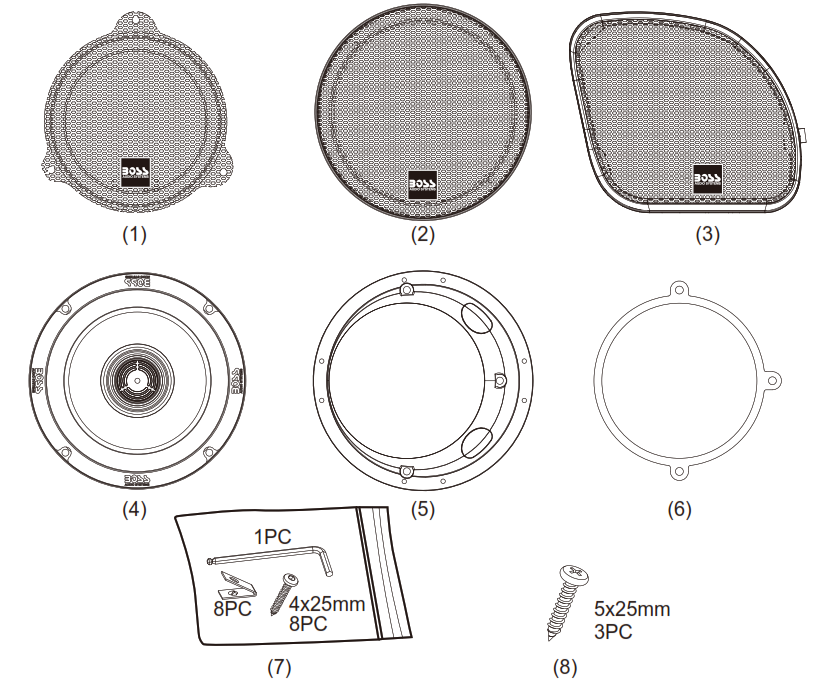
(1) HD Street Glide Grills (x2)(2) HD Tour Pak Grills (x2)(3) HD Road Glide Grills (x2)(4) Boss Audio 6.5” Speakers (x2)(5) Speaker adapters (x2)(6) EVA for speaker adapter (x2)(7) Screw bag for speaker(8) Screw bag for speaker adapters (5x25mm 3PC)
Important: Over-tightening mounting fasteners may result in damage to your motorcycle. Please refer to your service manual for proper procedures and torque specifications. Boss Audio is not responsible for damage resulting from improper installation techniques. This kit may not be compatible with some aftermarket head units.
GETTING STARTED
- Protect all painted surfaces.

- Remove seat and disconnect negative battery terminal.
- On 2009 and later models, it will help to remove the two T40 bolts, the ECM and tray
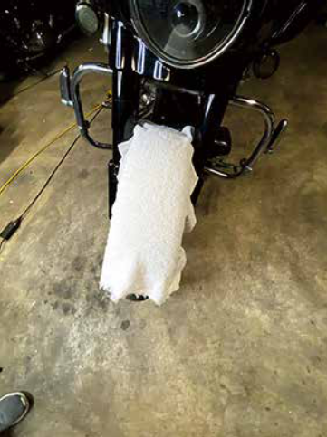
HD Front Speaker installation1998 – 2013 Street Glide /Batwing models:1. Cover the front fender.2. Remove (2) T-27 Torx bolts from inner fairing (under mirrors)
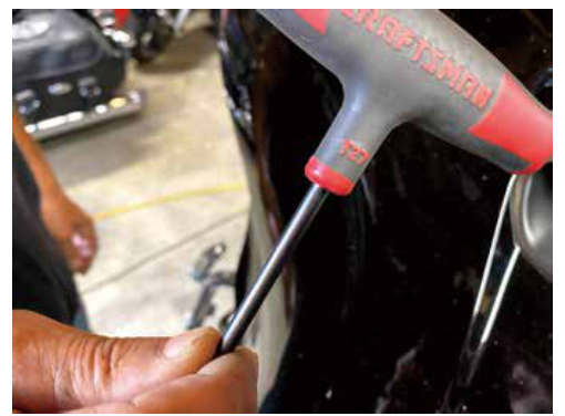
1. Cover the front fender.2. Remove (2) T-27 Torx bolts from inner fairing (under mirrors)
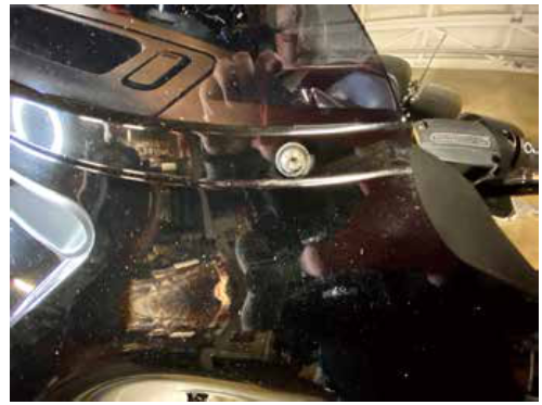
Note: Windshield and fairing will be loose once these screws are removed. Use extreme caution not to damage fairing or windshield. Lift away and unplug the headlight to remove the outer fairing.
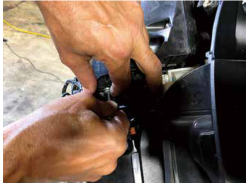
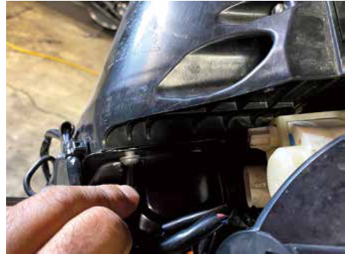
5. Remove windshield taking caution that the outer fairing is loose.6. Lift away and unplug the headlight to remove the outer fairing.7. Remove the remaining speaker screws and the speaker. Continue to kit assembly Loosen (6) T-25 Torx bolts from the bottom, middle, and top of the left and right sides of the inner fairing.
1998 – 2013 Road glide / Shark nose models:1. Loosen (6) T-25 Torx bolts from bottom, middle and top of left and right sides of the inner fairing.
2. Lift away the fairing, unplug the headlights and remove.4. Remove the speaker screws and the speaker.
2014 + Street and Road Glide1. Using 3 of the screws in the provided hardware, mount the speaker adapter to the inner fairing. The 4th inner bottom screw locations are not used on FLH/ batwing models. For Road Glide models, rotate the adapter until the notches in the adapter do not hit the factory mounting posts, and make sure the flat spots on the outside of the adapter are toward the outer edge of the fairing.2. Mount the new speaker with the hardware provided with the speakers. Do not re-use the factory screws. (Figure B) Note: For the Roadglide and Sharknose models, the longer screw may be needed in the lower mounting hole depending on the new speaker.
Amplifier and Amp plate Installation1998 – 2013 FLH/Batwing models:BHD34 Amplifier Mounting Plate Kit Contents
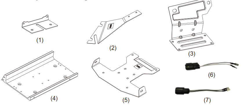
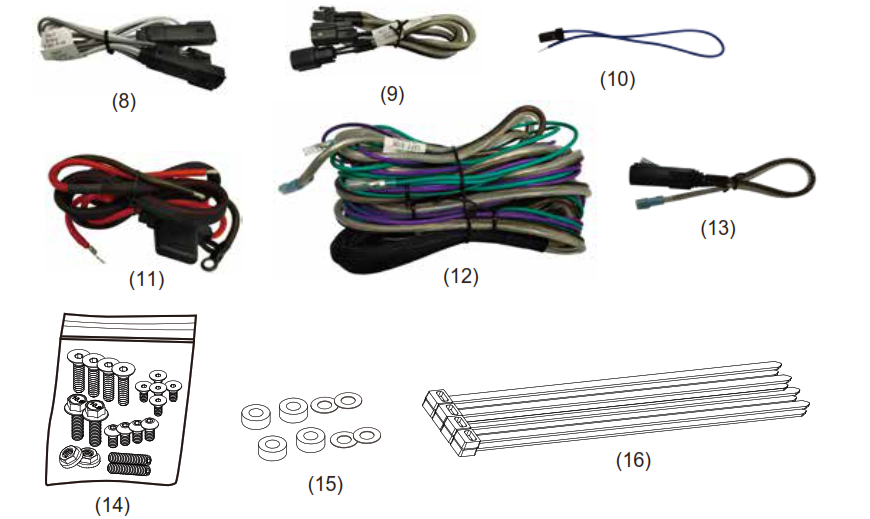
(1) Ultra Classic Street Glide and Tri Glide bracket (x1)(2) Road Glide mounting bracket (x1)(3) Road Glide mounting bracket (x1)(4) Universal Amp mounting plate (x1)(5) Road Glide Amp mounting bracket (x1)(6) Front speaker input for the Amplifier (White/Black) (x1)(7) Front speaker input for the Amplifier (Gray/Black) (x1)(8) Input from Amplifier front (x1)(9) Output from Amplifier front (x1)(10) Remote wire and pin (x1)(11) Power/Ground harness (x1)(12) Rear speaker input/output harness (x1)(13) Rear speaker connector (x2)(14) Screw Bag (x1)(15) Nylon spacers (x4) + Double sides tape (x4)(16) Wire Zip Tie Wraps (x8)
BPS400.4 4 Channel Class D Amplifier Contents
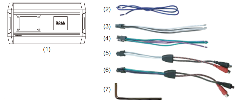
(1) Amplifier (x1)(2) Remote wire (x1)(3) Front output harness (x1)(4) Rear output harness (x1)(5) Front input harness (x1)(6) Rear input harness (x1)(7) Wrench (x1)
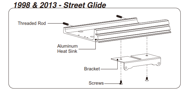
Step 1 – Mounting Plate and Bracket MountingWith the front faring removed. Using the Type(4) bracket, align bracket on the bottom side of the mounting plate using the bracket type indicators. On the top edge, you will screw in the two threaded pins into the mounting plate. These are used to align the mounting plate with the rubber bushings on top of the factory radio.
HD Street Glide 98 – 13Step 2 – Mounting Plate and Bracket MountingUsing the Type(1) and Type(4) brackets, align bracket on the bottom side of the mounting plate using the bracket type indicators. On the top edge, you will screw in the two threaded pins into the mounting plate. These are used to align the mounting plate with the rubber bushings on top of the factory radio.
Step 3 – Amplifier MountingMount amplifier upside down with the supplied screws to the mounting plate. Align the amplifier to the appropriate holes on the plate.HD Road Glide 98 – 13Step 2 – Mounting Plate and Bracket MountingUsing the Type(2), Type(3), and Type(4) brackets, align bracket on the bottom side of the mounting plate using the bracket type indicators. After you have the bracket attached to the mounting plate, remove the clutch side fairing bulkhead nuts. Place the bracket over the studs pushing the bracket upwards while tightening down using the factory hardware.

Step 3 – Amplifier MountingMount amplifier upside down with the supplied screws to the mounting plate. Align the amplifier to the appropriate holes on the plate.
Amplifier Wiring
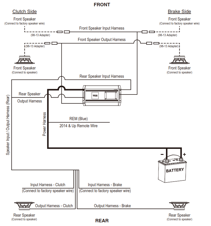
Once the amplifier is mounted, you can now begin plugging in the wiring harness in their appropriate sockets. Plug the switched power harness into the 2-pin amp connector on the throttle side of the fairing. Note: Be careful when plugging in the harnesses to the appropriate socket. The 4-pin Molex plugs for the Input / Output Harnesses fit in both sides of the amplifier.Step 4 – Fairing Speaker WiringUnplug the factory speaker wires from the speaker and plug them directly into the Front Speaker Input Harness. These are labeled clutch and brake sides. Now you can plug the new Front Speaker Output Harness onto your new speaker terminals. Route power/ground through fairing. Including installing rear speaker wires, feed the Rear Speaker Input / Output Harness through fairing towards the rear of the speaker.5 – Routing Power Harness / Rear Speaker HarnessPass the Power / Ground Harness and Rear Speaker Harness through the fairing and route next to the factory wiring harness. Routing the new wire harnesses along with the factory harness is recommended. Be sure to zip tie the harnesses together for a clean, tight fit. Due to the size wire for the Power / Ground Harness and Rear Speaker Harness, it is recommended to route the wiring under the gas tank along the top of the frame on the motorcycle.Note: Refer to the motorcycle manufacturer owner’s manual for bike. instructions regarding gas tank removal.Step 6 – Rear Speaker InstallationWith the seat already removed, route the Rear Speaker Harness toward the rear of the motorcycle over the fender along the brake side of the motorcycle. Unplug factory speaker wires from the speaker and plug them directly into the Rear Speaker Input / Output Harness. These are labeled clutch and brake side.
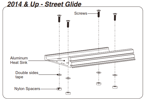
Amplifier and Amp plate Installation 2014 – Newer Street Glide FLHT/Batwing models:AMP INSTALLATION*NOTE* after installation this vehicles head unit must be flashed to get proper sound from the upgraded system. Please see the following link to find a recommended HD shop that can flash the stock system. https://technoresearch.info/tuning-centers-map/
If you have a 2020 Street or Tri Glide, the following steps must be completed before amplifier installation: Remove four screws from the HD Connect Module. Remove Module from Bracket. Relocate Module to the clutch side of the radio and secure with two 8” zip ties included. NOTE: There may be some connectors that will need to be relocated off the radio chassis for the amp bracket to fit.
- Fasten the amplifier to the bracket with the supplied hardware.Insert the bolts through the bottom of the bracket and install the locknuts to the amplifier.
- After finishing System Setup, use the supplied hardware and fasten the amp/bracket assembly to the radio chassis with the 10-pin connector and power connector facing the throttle side.HARNESS INSTALLATION
- Plug the harness into the amplifier and route the speaker wires to their respective locations. Separate the speaker connectors and plug in the amplifier harness to each speaker.
- Plug the 4-pin male, rear audio connector into the 4-pin female rear audio signal connector coming from the radio harness.
- Plug the switched power harness into the 2-pin amp connector on the throttle side of the fairing.
- Plug the Supplied blue wire on the Boss Audio Amplifier kit into the switched power harness lead with one wire. This allows for an accessory 12V port to remain available.
- Route the power leads along the clutch side of the frame neck, in the electrical caddy to the seat area.
- Reconnect the battery terminals and pull the excess harness slack back into the fairing. Create a slack loop with excess harness slack.
- Plug the radio in and set the gain.
- Test component function and set the gain to optimize system performance.
- Carefully reassemble the motorcycle and enjoy your new audio kit
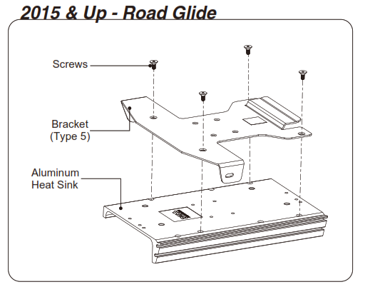
Amplifier and Amp plate Installation 2014 – NewerRoad Glide FLTR 2015 – Newer:*NOTE* after installation this vehicles head unit must be flashed to get proper sound from the upgraded system. Please see the following link to find a recommended HD shop that can flash the stock system. https://technoresearch.info/tuning-centers-map/
- Remove the radio. Unplug the four connectors on the back of the radio. Remove the four Allen head bolts holding the radio to the chassis.Gently remove the radio from the chassis.
- Install the Boss Audio amplifier onto bracket Type(4) with supplied hardware. Slide the end of the amplifier with the power connector port into the bracket and fasten with supplied hardware. Install the bolts from the bottom and fasten the locknuts onto the amplifier.
- Carefully install bracket/amplifier assembly onto radio chassis by installing the assembly through the radio face port in the fairing and sliding the tabs of the bracket over the chassis. The amp bracket assembly mounts under the radio.HARNESS INSTALLATION
- Plug the harness into the amplifier and route speaker wires to their respective connectors. Separate the speaker connectors and plug in the amplifier harness to each speaker. Important: Over-tightening mounting fasteners may result in damage to your motorcycle. Please refer to your service manual for proper procedures and torque specifications. Boss Audio is not responsible for damage resulting from improper installation techniques.
- Plug the switched power harness into the 2-pin amp connector on the throttle side.
- Plug the blue wire on the Boss Audio harness into the switched power harness lead with one wire. This allows for an accessory 12V port to remain available.
- Route both power leads along the clutch side of the neck and through the electrical caddy to the seat area.
- Reconnect the battery terminals.
- Plug the radio in, but do not reinstall it until the gain has been set.
- Test component function and set the gain to optimize system performance.
- Carefully reassemble the motorcycle and enjoy your new audio system!
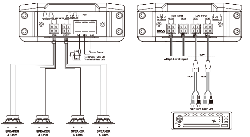
This kit comes ready to plug directly into 2014 & Up Harley-Davidson Motorcycles using factory-style connectors. If you are installing on a 1998-2013 motorcycle, you will need to use the wire connector adapters to connect to the factory wire harness and new speakers.NOTE: This wiring diagram is for a standard 4-Channel amplifier installation. If you are using a 2-Channel amplifier, DO NOT use the Rear Input / Output Harness.
BOSS Audio Systems3451 Lunar Court • Oxnard, CA 93030www.bossaudio.com805-751-4853 Customer ServiceTech Support: www.bossaudio.com/support
![]()
References
[xyz-ips snippet=”download-snippet”]