BOSSAUDIO Class D Monoblock Power
Amplifier User Manual
![]()
BE600.2DTwo Channel MOSFET Car Audio Amplifier
BE300.4DFour Channel MOSFET Car Audio Amplifier
BE2200.5DFive Channel MOSFET Car Audio Amplifier
BE1200.1DMonoblock/full range MOSFET Car Audio Amplifier
Congratulations on your purchase of a ![]()
![]() Amplifier.
Amplifier.
It has been designed, engineered and manufactured to bring you the highest level of performance and quality, and will afford you years of listening pleasure.
Thank you for making ![]() your choice for car audio entertainment!
your choice for car audio entertainment!
Introduction
With the ![]()
![]() amplifier series, we are introducing four new amplifiers, all designed in the USA. This new series includes one monoblock/full range, one 2-channel, one 4-channel amplifier, one 5-channel amplifier.
amplifier series, we are introducing four new amplifiers, all designed in the USA. This new series includes one monoblock/full range, one 2-channel, one 4-channel amplifier, one 5-channel amplifier.
All BOSS models feature variable low pass and high pass (except monoblock amp) crossovers and variable input gain controls.
For further flexibility in the use of a subwoofer, 0-+12dB
Bass Boost control has been included on all amplifiers. You can control the subwoofer level with the remote level control module.
![]() understands that amplifiers are placed in many different kinds of installations, so we incorporated a very flexible system of controls in these amplifiers in order to help you integrate the amp into your system regardless of the nature of your input source.
understands that amplifiers are placed in many different kinds of installations, so we incorporated a very flexible system of controls in these amplifiers in order to help you integrate the amp into your system regardless of the nature of your input source.
What is included?
When first unpacking your new amplifier, please check first that the package contains all of the items below. If something is missing, contact the store where you purchased the amplifier.
 amplifier
- Remote subwoofer control (BE1200.1 D /BE2200.5D)
- Input/output wire harness
- Four (4) mounting screws
- Power terminal adapter
- User’s manual
Features
Your new ELITE amplifier features the following:
• Class D Topology• Bridgeable outputs (Except BE1200.1 D)• MOSFET PWM (Pulse Width Modulated) Power Supply• 2 Q stable stereo operation with output power increase (10stable for BE1200.1 D)• Thermal and speaker short protection• Soft turn-on circuit• Remote turn-on/turn-off circuit• Variable input gain control• Variable low pass filter• Variable high pass filter (Except BE1200.1 D)• Variable Subsonic filter (BE1200.1D)• Variable Oto+ 12dB Bass Boost• RCA WIRE low level inputs• LED power and protection indicators• Black anodized heatsink• Remote subwoofer control (BE1200.1 D IBE2200.5D)• ILLUMINATED end panels
About 2 Ω operation
Your BOSS amplifier has been designed to operate efficiently at loads down to 2 Ω. (BE1200.1D down to 1 Ω)
When operating at 2 Ω, the amplifiers will increase their output power by approximately 50%. The current draw will also increase byabout the same amount, so be sure you have enough current to run the amplifiers into a 2 Ω load.
Before installing any electrical accessories to your vehicle, always make sure the vehicles electric system is equipped to handle the extra electrical load.
General precautions
Before installing and using your new BOSS amplifier, please become familiar with all the information contained in this manual.
Please keep this manual in a safe place for future reference.
- Do not open or attempt to repair this unit yourself. Dangerous high voltages are present which may result in electric shock. Refer any repairs to a qualified service technician.
- To avoid risk of electronic shock or damage to the amplifier, do not permit any of this equipment to become damp or wet from water or drinks. If this does occur, immediately unplug the power wires and send the amplifier to your local dealer or service center as soon as possible.
Installation precautions
Before you drill or cut any holes, investigate your car’s layout very carefully. Take special care when you work near the gas tank, fuel lines, hydraulic lines and electrical wiring.
Never operate the amplifier when it is unmounted. Attach all audio system components securely to prevent damage, especially in an accident.
Before making or breaking power connections in your system, disconnect the vehicle battery. Confirm that your head unit or other equipment is turned off while connecting the power and/or speaker(s).
If you need to replace the power fuse, replace it only with a fuse identical to that supplied with the amplifier. Using a fuse of a different type or rating may result in damage to your audio system or your amplifier which is not covered by the manufacturer’s warranty.
Mounting the amplifier
- Find a suitable location in the vehicle in which to mount the amplifier.
- Make sure there is sufficient air circulation around the intended mounting location.
- Mark the location for the mounting hole screws by positioning the amplifier where you wish to install it. Use a scribe or mounting screw, inserted through each of the amp’s mounting holes, to mark the mounting surface. If the mounting surface is carpeted,measure the hole centers and mark with a felt tip pen.
- Drill pilot holes in the mounting surface for the mounting screws. Place the amplifier in position, and attach the amplifier to the mounting surface securely using screws.
SHOCK HAZARD! Do not open the case of this product. There are dangerous voltages present within the unit. There are no user-serviceable parts within the unit.
Connecting the amplifier
Before doing any wiring, look through this manual and identify the diagrams to follow for power, input and speaker connections for your particular installation. Be sure you understand all the connections before you proceed.
- Connect the power ground terminal to the closest point on the chassis of the car. Keep this ground wire to less than 39″ (100 cm) in length. Use the same size gauge wire as the power wire.
- Connect the remote terminal to the remote output of the head unit using 16 gauge (or larger) wire.
- Connect an empty fuse holder within 18″ (45 cm) of the car battery, and run 4 gauge cable from this fuse to the amplifier location.
- Check that the fuse holder is empty. Then connect the fuse holder to the “BATT+” connection on the amplifier.
- If multiple amplifiers are being used in your system, either:
- Run a separate pair of cables from the battery and a chassis ground point to each amplifier. Each (+) cable must have its own inline fuse.-or-
- Run a #4 cable from the fuse holder at the battery to a distribution block at or near the amplifier’s location. Then run separate cables from the amplifier to this distribution block and to independent chassis ground points.
- Connect all line inputs and outputs (if used) using high-quality cables. Connect all speakers, following the diagrams in this manual. Be sure to observe proper polarity to avoid audio phase problems.
- Insert fuse(s) into the battery fuse holder(s).
- Recheck all connections before powering up the amplifier.
- Set all level controls to minimum position, and set all crossover controls/switches to the desired frequency points.
- Power up the head unit and the amplifier. Then set the volume control on the head unit to about 3/4 volume, and adjust the amplifier’s input level control(s) to just below the level of distortion.
- Further fine tuning of the various controls may be necessary to obtain best results.
Don’t misuse the level control!
Do not mistake the input level control for a volume control! It is designed ONLY to match the output level of your audio source to the input level of your amplifier.
Do not adjust this input level to maximum unless your input level requires it.
Ignoring these instructions will result in an input overload to the amplifier, and excessive audio distortion. It can also cause the protection circuit to engage.
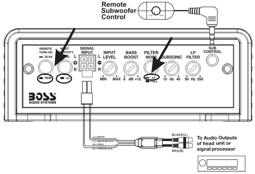
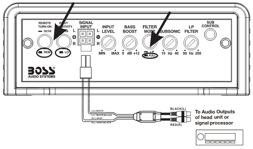
Low Level Input Wiring
Low-level (RCA) input wiring is preferred for best audio performance. Always use a high-quality RCA cable for best audio performance.
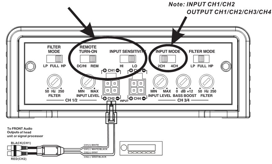
The 4-pin SIGNAL INPUT port is designed for LOW level input or Hi-level input. Set the REMOTE TURN ON switch to REM and INPUT SENSITIVITY switch to LO when low-level signal applied.
2-Channel Amplifier
BE600.2D

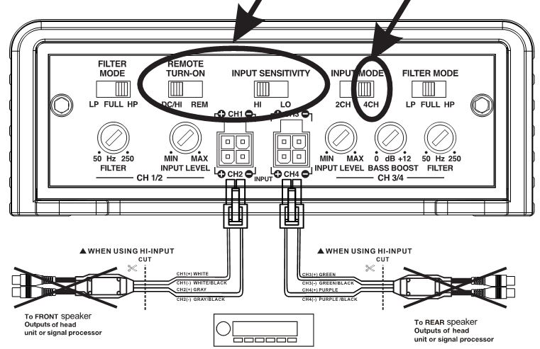
4-Channel Amplifier
BE300.4D
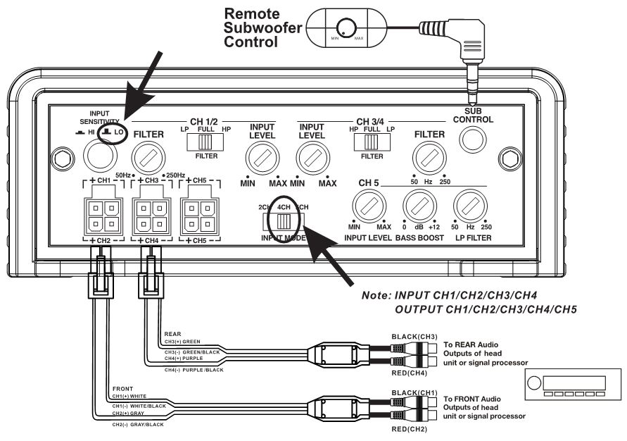
4CH INPUT MODE
Note: INPUT CH1/CH2/CH3/CH4OUTPUT CH1/CH2/CH3/CH4
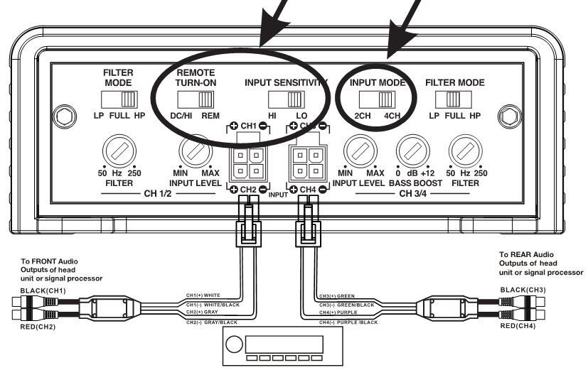
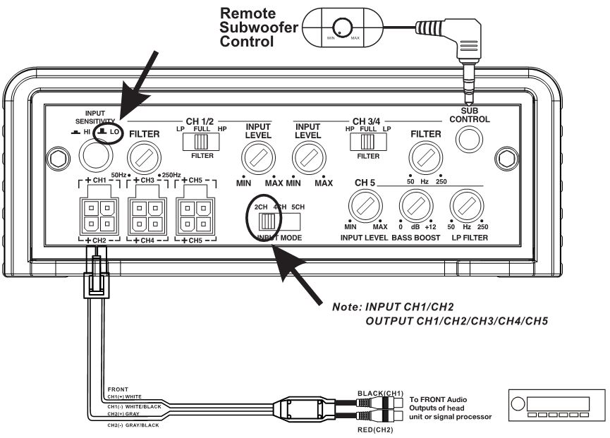
2CH INPUT MODE
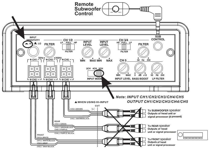
5-Channel Amplifier
BE2200.5D
5 CH INPUT MODE
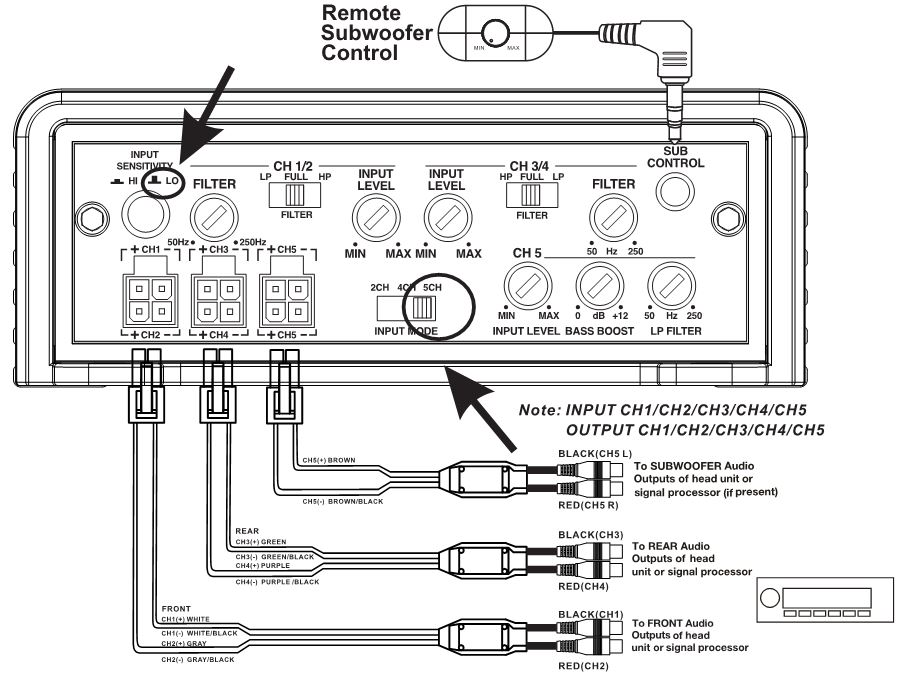
4CH INPUT MODE
2CH INPUT MODE
Full Range Monoblock Amplifier
BE1200.1D
Monoblock Mode
Full Range Mode
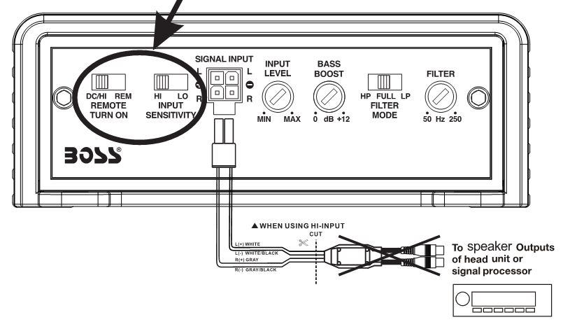
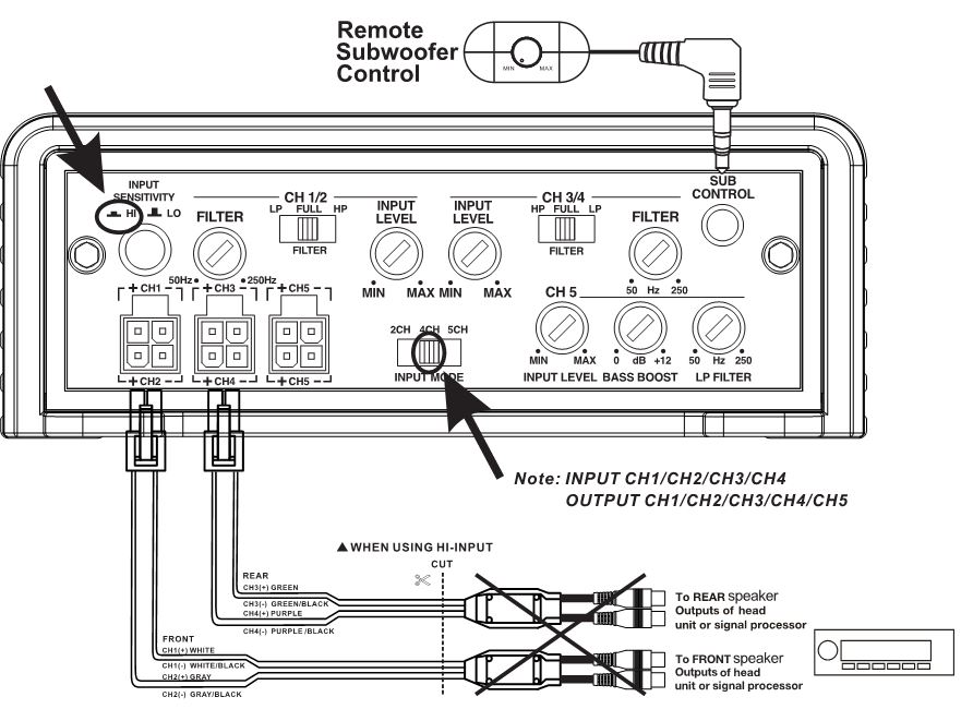
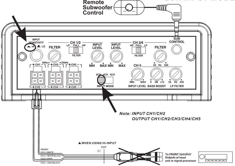
High Level Input Wiring
The high level input(s) should only be used when your head unit lacks RCA outputs. If the RCA outputs are not present, connect the speaker outputs from the receiver to the SIGNAL INPUT connector of the amplifier. Be sure to observe polarity to avoid audio phase problems.
The 4-pin SIGNAL INPUT port is designed for LOW level input or Hi-level input. Set the REMOTE TURN ON switch to DC/HI and INPUT SENSITIVITY switch to HI when high-level signal applied. NO NEED to connect the remote wire at the REM terminal of the POWER connector. The amp will auto-sense the high-level input and then power up the amplifying system.
2-Channel Amplifier
BE600.2D
4-Channel Amplifier
BE300.4D
4CH INPUT MODE
2CH INPUT MODE

5-Channel Amplifier
BE2200.5D
5CH INPUT MODE
4CH INPUT MODE
2CH INPUT MODE
Mono block Amplifier
BE1200.1D

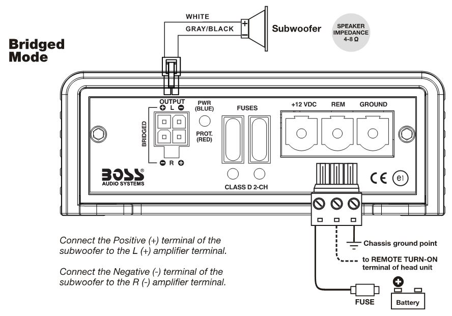
Power and Speaker Wiring
2 Channel and Bridged Modes
2-Channel AmplifierBE600.2D

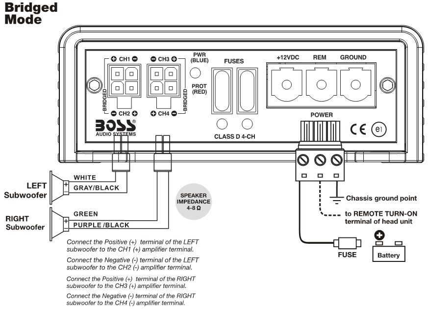
4 Channel and Bridged Modes
4-Channel AmplifierBE300.4D

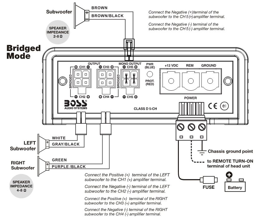
5 Channel and Bridged Modes
5-Channel AmplifierBE2200.5D

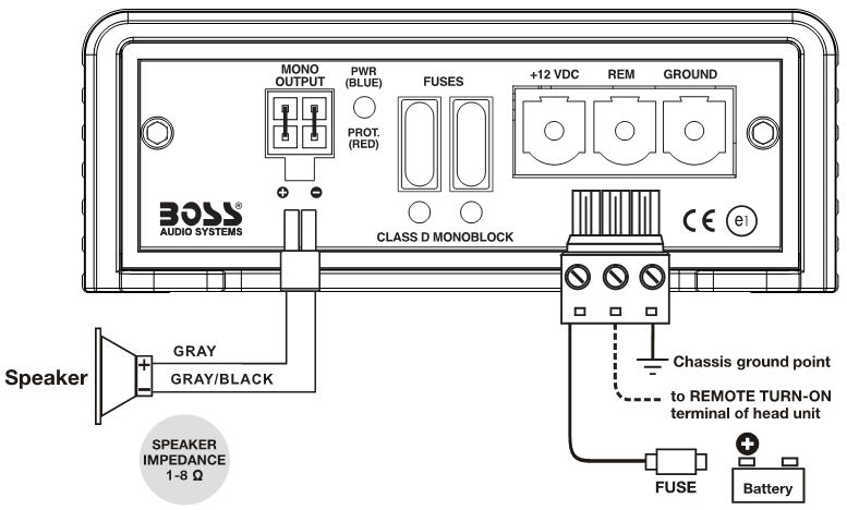
Full Range Monoblock Mode
Full Range Monoblock AmplifierBE1200.1D
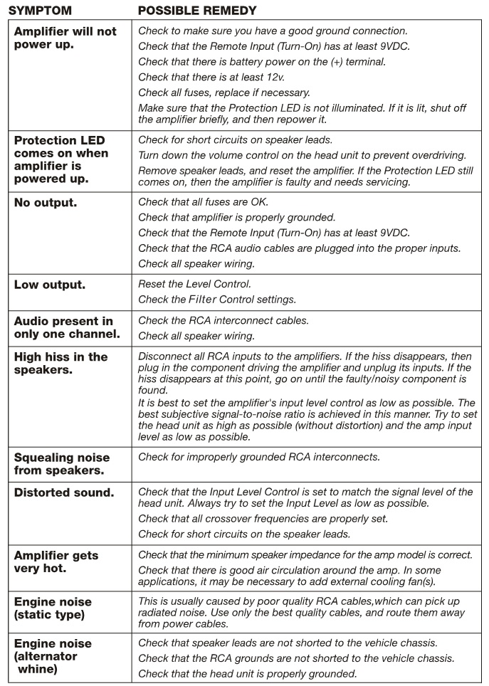
Troubleshooting
If you experience operation or performance problems with this product, compare your installation with the electrical wiring diagram on the previous pages. If problems persist, read the following troubleshooting tips which may help eliminate the problems.
Specifications
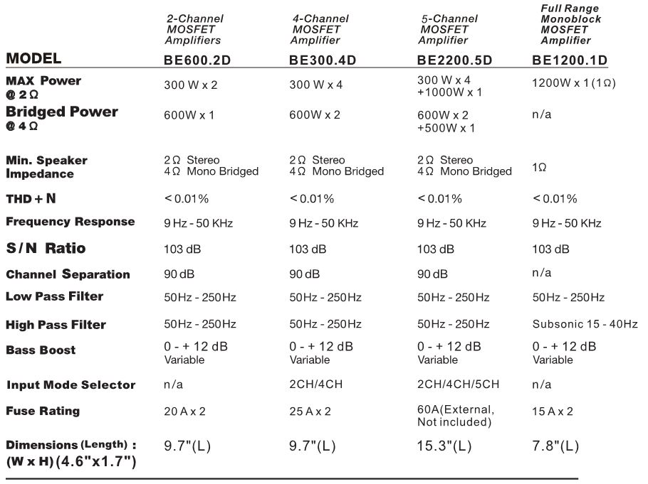
![]()
BOSS Audio Systems3451 Lunar Court • Oxnard, CA 93030www.bossaudio.com805-751-4853 Customer ServiceTech Support: www.bossaudio.com/support
![]()
0226
[xyz-ips snippet=”download-snippet”]