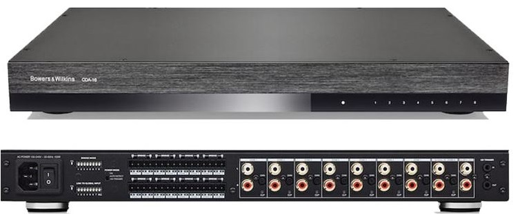
Bowers Wilkins Distribution Amplifier

Welcome to Bowers & Wilkins and CDA-16Thank you for choosing Bowers & Wilkins. When John Bowers first established our company, he did so in the belief that imaginative design, innovative engineering, and advanced technology were keys that could unlock the enjoyment of audio in the home. His belief is one that we continue to share and inspires every product we design, tailored for new audio experiences outside of the home.Our CDA-16 distribution power amplifier can drive any Bowers & Wilkins custom installation speaker to new heights of performance. Offering 16 channels of power, the CDA-16 can enable your whole home with sound yet takes up minimal space thanks to its compact 1U design. Its configurable specification supports bridging its Class D stereo channels into even more powerful mono outputs if needed.
Features
- 16 channels distribution amplification in 8 zones with a powerful 100 watts per channel to deliver high-resolution audio.
- Engineered to work with any Bowers & Wilkins installation speakers. · Highly flexible usage/configuration Zone L/R outputs can be bridged to provide a mono output of double the power.
- Three power mode control options on, auto-detect, or 12V trigger.
- Robust and reliable protection features, preventing damage due to overload, short circuits, or heat.
- Ultra-compact rack-mount design (1 rack unit), easy to install and configure.
1. CDA-16 Carton Contents
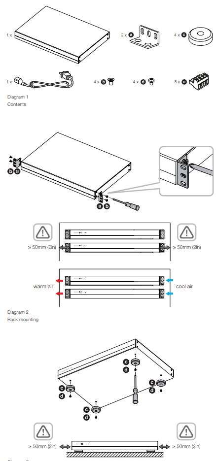
1 x Power cable2 x Rack-mount ears4 x Rack-mount ears screws4 x Feet4 x Feet screws8 x 5.08mm Pitch 4-way Phoenix Comicon style
2. Installation
2.1 Rack mounting
CDA-16 is intended to be installed in a standard 19inch equipment rack. It is supplied with rack mount ears, but not rack mount bolts and nuts. Ensure that, once mounted in the rack, the amplifier is well ventilated and that the ventilation apertures are not obstructed. If the system is taken out of use for a long period, disconnect the amplifier from the mains power supply.The CDA-16 is supplied with two rack mounting ears for installation in standard equipment racks. Attach the brackets by inserting machine screws through each bracket into the threaded holes in the side of the amplifier, see Diagram 2.![]() To prevent damage, maintain adequate ventilation space to the sides of the amplifier. CDA-16 can be stacked vertically but be sure not to place the amplifier next to other components or against the side of a cabinet. Doing so will block ventilation openings.
To prevent damage, maintain adequate ventilation space to the sides of the amplifier. CDA-16 can be stacked vertically but be sure not to place the amplifier next to other components or against the side of a cabinet. Doing so will block ventilation openings.
2.2 Foot mounting
CDA-16 can also be table-mounted and is supplied with feet and feet screws, see Diagram 3.Ensure that, once positioned, the amplifier is well ventilated and that the ventilation apertures are not obstructed. If the system is taken out of use for a long period, disconnect the amplifier from the mains power supply.![]() To prevent damage, maintain adequate ventilation space to the sides of the amplifier. CDA-16 can be stacked vertically but be sure not to place the amplifier next to other components or against the side of a cabinet. Doing so will block ventilation openings.
To prevent damage, maintain adequate ventilation space to the sides of the amplifier. CDA-16 can be stacked vertically but be sure not to place the amplifier next to other components or against the side of a cabinet. Doing so will block ventilation openings.
3. Controls and Connections
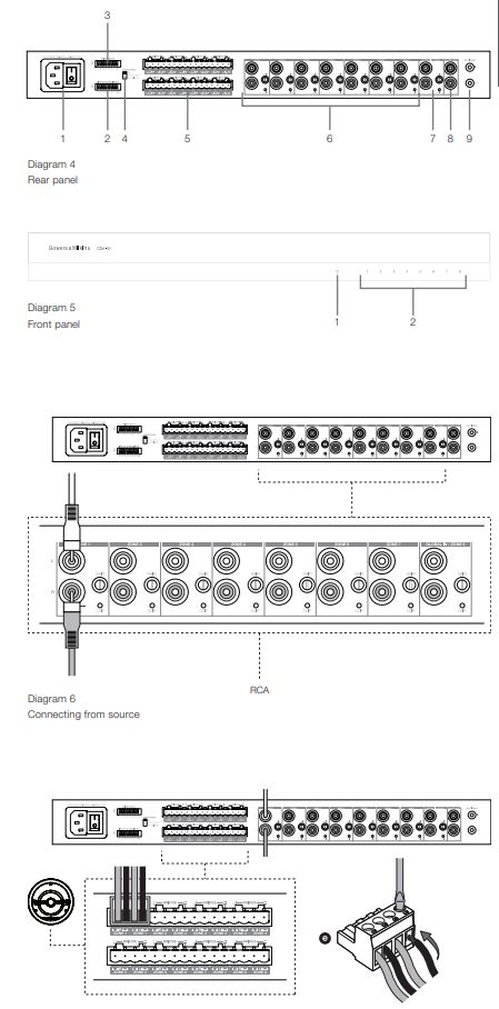
Rear panel sockets and switches
- Power input socket (IEC C14)
- Link to global input
- Bridge mode
- Power mode
- Zone outputs
- Zone 1 7 inputs
- Zone 8 input / Global in
- Global out
- 12 V trigger in / out
Front panel controls
- Power LED
- Zone status LEDs
4. Connecting
![]() Connecting speaker wires or input cables while the amplifier is powered may cause electrical shock and could damage the amplifier. Unplug the power cord before making connections.
Connecting speaker wires or input cables while the amplifier is powered may cause electrical shock and could damage the amplifier. Unplug the power cord before making connections.
4.1 Connecting from source
CDA-16 accepts stereo line-level audio connections to its RCA Phono sockets. Each ZONE input will pass amplified audio to the respective zone speaker output. Alternatively, each ZONE can be linked individually to the GLOBAL IN (shared with ZONE 8).1. Connect the audio cable to the ZONE inputs (1 8) RCA Phono inputs, see Diagram 62. (Optional) Connect the audio cable to GLOBAL IN (ZONE 8) and link speaker outputs to the GLOBAL IN by moving the dip switch up for that zone to the ON position.
4.2 Connecting to speakers
CDA-16 can power eight stereo zones of audio and has phoenix-style terminal blocks for speaker connections. Speakers can also be wired to bridge channels to increase the power available to the speakers.
To connect stereo speakers:
1. Connect the speaker cable to the phoenix connector and reinsert it into the amplifier, see Diagram 7.
![]() The common signal of these speaker outputs must not be connected together or to any other common signal. Do not connect the L and R (negative) terminals together. Doing so will result in a fault condition and the amplifier will either shut down or not work properly.
The common signal of these speaker outputs must not be connected together or to any other common signal. Do not connect the L and R (negative) terminals together. Doing so will result in a fault condition and the amplifier will either shut down or not work properly.![]() Check the polarity of the speakers and wires before connecting to the amplifier.
Check the polarity of the speakers and wires before connecting to the amplifier.
To connect bridged speakers, see Diagram 8:1. Set the BRIDGE MODE dip switch if needed for each zone by moving the dip switch up for that zone to the ON position.
2. Connect + terminal from the speaker to the + terminal of the right channel (R).
3. Connect the – terminal from the speaker to the – terminal of the left channel (L) on the amplifier.
The two terminals for a bridged pair of speakers area marked by + BRIDGE -.
In bridge mode, both amplifiers in the zone combine to make a mono output of double the power. When in bridge mode only the left channel RCA input to the zone is active so please connect the input to this jack.
Note: The minimum load impedance in bridge mode is 8Ω. Connecting 4Ω loads may result in lower output power, distortion, and overheating.
5. Setting POWER MODE
CDA-16 can be set up to automatically power on when needed. The POWER MODE switch, see Diagram 9, allows CDA-16 to be powered on at all times, turned on with a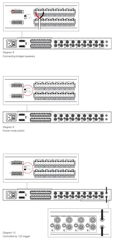 12V trigger, or turned on when an audio signal is present at any audio input.
To set up CDA-16 to be always on:
1. Slide the POWER MODE switch to ON.In this mode, CDA-16 will be always on unless the power cord is unplugged or the power switch by the power plug is toggled off.
To set up CDA-16 turn on by AUTO DETECT:
1. Slide the POWER MODE switch to AUTO DETECT
In this mode, CDA-16 will turn on when an audio signal is sensed on the audio input.
Note: Only the amplifier zone that senses audio will turn on when in AUTO DETECT mode.
To set up CDA-16 to be controlled by a 12V trigger:
1. Slide the POWER MODE switch to 12V TRIGGER.
2. Connect the 12V trigger cable to the 3.5 mm 12V TRIGGER IN jack socket, see Diagram 10.
3. (Optional) Connect the 12V TRIGGER OUT jack socket to another amplifier to link their power control together.
In this mode, CDA-16 will turn on when a 12V signal is present on the 12V Trigger Input. This 12V trigger input can be wired to the 12V trigger output from an audio matrix switch or a relay.
Diagram 10 Controlled by 12V trigger
Note: All amplifier zones turn on when a 12V trigger is received in 12V TRIGGER mode.
6. GAIN Controls and CLIP Indicator
The GAIN controls are located next to each Zone input on the rear panel. They are operated by rotating the control clockwise to increase the GAIN or counterclockwise to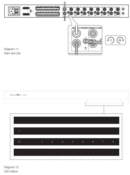 decrease the GAIN. When turned fully counterclockwise, GAIN is reduced to 0 and no output signal will be present. When turned fully clockwise, the GAIN of the amplifier is +34.9dB.To operate the GAIN control, rotate the control’s knob so that the desired level is achieved, a small, flat-tipped screwdriver is typically used, see Diagram 11.
Note: Do not apply excessive torque to the control, it will turn easily unless at the ends of its travel
The CLIP indicator LED is located below the GAIN control. The flashing CLIP indicator indicates clipping is present while playing source input.
7. LED status

8. Support
Should you require further help or advice regarding your CDA-16 please visit the support site here bowerswilkins.com/support.
Environmental InformationThis product complies with international directives, including but not limited to the Restriction of Hazardous Substances (RoHS) in electrical and electronic equipment, the Registration, Evaluation, Authorisation, and restriction of Chemicals (REACH), and the disposal of Waste Electrical and Electronic Equipment (WEEE). Consult your local waste disposal authority for guidance on how properly to recycle or dispose of this product.
Specifications
Audio SpecificationsLoad impedance range: >3Ω per channel (>6Ω in bridge mode)Output Power per channel, non-clipped: >50W into 8Ω >100W into 4ΩOutput Power bridge mode, non-clipped: >200W into 8ΩOutput Power total, all channels: >400W short term >200W continuous averageDC offset voltage: <50mVFrequency Response (-3dB): <10Hz to >50kHz, any load impedanceFrequency response accuracy 20Hz-20kHz: ±0.5dBSignal to Noise ratio (Ref. 50W/8Ω): >100dB A-WeightedTHD+N (1kHz, 12.5W, 4Ω): typically 0.05%Voltage Gain: 34.9dB to – infinity, adjustableInput impedance: 15KΩMaximum input voltage: 6.8V peak (4.8V RMS sine wave)Signal sense threshold: 2.5mV (independent of Gain setting)Wake-up time: <0.2s (If other zones active) <2s (From all zones inactive)Turn-off time: 15 minutes from the last signal detected12V trigger input threshold: typically 3V (recommended input is 5-15V)
Controls & IndicatorsFront panel: 1 x Power LED (unit active White, Fault Red) 8 x Zone status LEDs (Signal present White, Fault Red)Rear panel: 8 x 2-position DIP switches (link to global input) 1 x 3-position switch (power mode: on, auto detect, 12V trigger) 8 x input gain control with Clip indicator LEDs
ConnectorsInput:8 x RCA (pair) Phono socket, line in (global in shared with Zone 8)Output:1 x RCA (pair) Phono socket (global out)8 x 5.08mm Pitch 4-way Phoenix Combicon style12V trigger control:1 x 3.5 mm jack – 12V trigger IN1 x 3.5 mm jack – 12V trigger OUT (Maximum 100mA pass-through)
PowerPower consumption: <0.5W All zones inactive <45W All zones idling 300W maximum average 1,000W peakAC supply: 100-240V 50/60HzAC inlet: IEC C14, switched
ThermalThermal dissipation:1.7 BTU/hr (standby),150 BTU/hr (Idle),400 BTU/hr (max)
DimensionsHeight: 44.5 mm (1.8 in) 1U [55.5 mm (2.2 in) plus feet]Width: 437 mm (17.2 in)Depth: 310 mm (12.2 in)Net weight: 4.5kg (9.9lb)
Finish: Black
References
[xyz-ips snippet=”download-snippet”]