![]()
BY- W M6 SUHF Wireless Microphone SystemInstruction Manual
Instruction
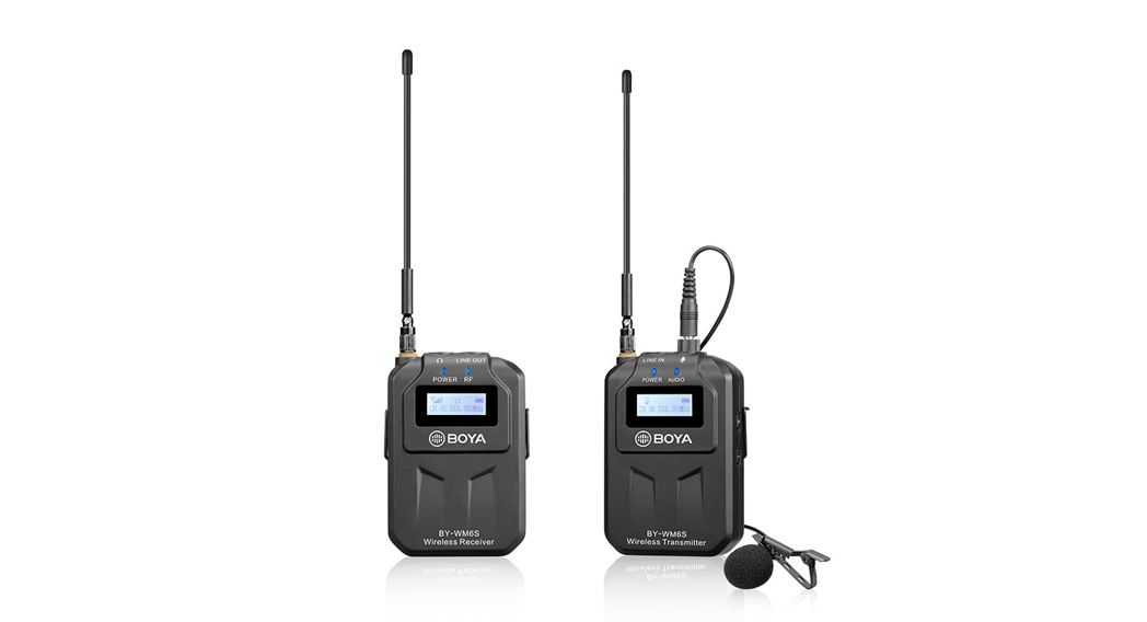
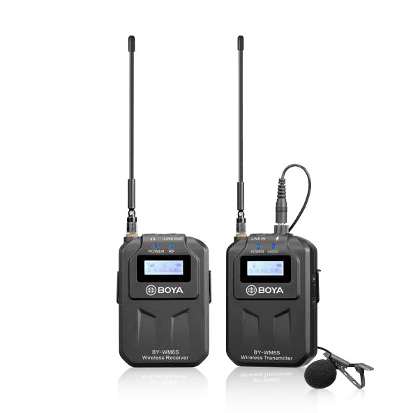
Thank you for purchasing BOYA BY-WM6S!The BOYA BY-WM6S is a new generation UHF wireless microphone system, compatible with smartphone, tablet, DSLR camera, camcorder, audio recorder and more.With low-interference capacity and UHF transmission with true-diversity reception, it helps users guard against many kinds of troubles, even under difficult shooting conditions, and delivers the broadcast sound quality and integrity of audio.It runs on built-in rechargeable batteries or powered by Type-C DC 5V.This system is designed with a compact and rugged housing and a detachable antenna that easily carries to indoor and outdoor environments.
Features
- For mobile journalist, vlogger, filmmaker and videographer
- Compatible with smartphone, tablet, DSLR camera, camcorder, audio recorder
- Deliver clean and broadcast-quality sound for recording
- UHF transmission with 48 channels
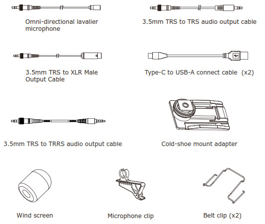
- Omnidirectional lavalier microphone included
- Easy-to-read LCD displays
- USB Type-C ports for battery recharging
- Rugged all-metal construction
- Up to 70m (230′)(without obstacle) operation range
- Mute function
- 3.5mm headphone output
The BY- W M 6 S consist s of one body- pack t ransm it t er ( TX6S) , a port able receiver ( RX6S) , and t heir accessories as following: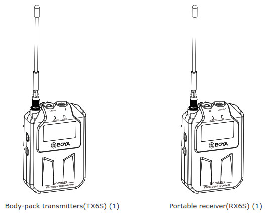
Transmitter
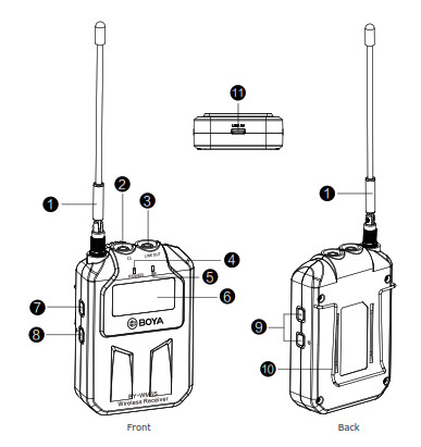
- Antenna
- LINE IN
- Microphone inputConnect the supplied lavalier microphone here. Fully insert the microphone’s 3.5mm TRS plug and make sure it clicks into place, then lock the plug. To remove, release the locking mechanism, then pull the plug out.
- Power indicatorFor more details about LED indicator, please refer to as following:
Status LED Status “POWER” “AUDIO” “RF” The transmitter and the receiver is connected Transmitter √ √ / Receiver √ / √ The transmitter and thereceiver is disconnected Transmitter √ √ / Receiver √ / x The transmitter and the receiver is connected. And muting function is on. Transmitter √ Flashes blue / Receiver √ / x The transmitter or the receiver is in low power Transmitter Stays red √ / Receiver / √ The transmitter or thereceiver is in charging Transmitter Flashes red √ / Receiver / √ Notes: “√” means the LED light is on. “×” means the LED light is off.
- AUDIO indicator
- LCD displayFor details, please refer to “LCD display Operation Guide”on page 8
- Power/Mute button1) Long press the power of the transmitter ON or OFF.2) Short press to mute
- SET buttonChannel / Light setting
- + (+ selection)/ (- selection) buttonsPress these buttons to set the transmission channel, light setting.
- Belt clip
- USB Type-C charging port
Receiver![]()
- Antenna
- Headphone output
- LINE OUT(3.5mm diameter stereo mini jack) Connect one end of the supplied stereo 3.5mm TRS to TRS or XLR to XLR Male output cable here, and the other end to the microphone input on a DSLR camera, camcorder, mixer, or amplifier etc.
- Power LEDFor more details about LED indicator, please refer to page 5.
- RF indicator
- LCD displayFor details, please refer to “LCD display Operation Guide”on page 8
- Power buttonLong press the power of the transmitter ON or OFF.
- SET buttonChannel / Volume / Light setting
- + (+ selection)/ (- selection) buttonsPress these buttons to set the transmission channel, volume and light setting.
- Belt clip
- USB Type-C charging port
What’s difference?
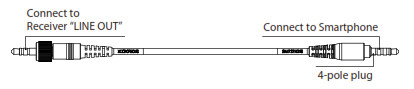
- 3.5 mm TRRS connector– For Smartphone, tablet, Mac or laptop with combo headphone/mic jack

- For cameras, camcorders, audio recorders and other audio/video recording devices.
- USB Type-C to USB-A charging cable– Using this cable, the devices with USB-A output can deliver power to BY-WM6S.
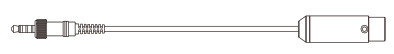
- The end of XLR is connected to audio devices with a standard XLR input, such as mixer, amplifier, and more.


LCD D display y Operation Guide Receiver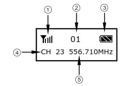
- Signal level
- Volum e set t ing ( 1- 16)– Press t he SET but t on t o volum e set t ing– Press t he + / – ( + / – select ion) but t on t o adj ust volum e.
- Battery indication
- Channel num ber ( 1- 48)
- Frequency
Transmitter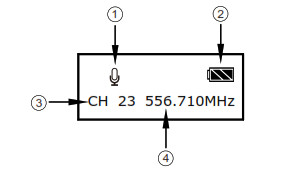
- MUTE button– Press t he SET but t on t o m ut e on.– When the icon show ” “, m ute function is on.
- Battery indication
- Channel num ber ( 1- 48)
- Frequency
Mute function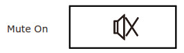 – Transm it t er is muteon.
Lock function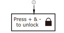
– LCD will be locked aut om at ically in 30 seconds.– Long press bot t om s ” + ” and ” – ” t o unlock.
Backlight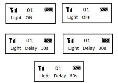 – Press the +/-(+/-selection) button to turn LCD backlight ON/OFF.– Light delay setting includes 10/30/60s options.
Charging status – This indication shows the battery is charging.
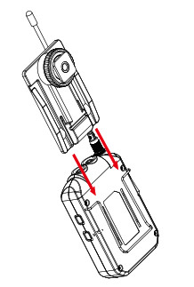
Attaching the shoe mount adapter
- Please attach the belt clip in the direction of the shown picture before attaching the shoe mount adapter.
- Slide the adapter down fitting into the space between the belt clip and the receiver.
- Make sure the adapter insert into vertical slot in parallel until it properly fixs into the horizontal groove and locks.
Setting the Transmitter and the ReceiverTo connect the transmitters and the receiver, follow these steps:
- Make sure the supplied lavalier microphones are connected to the transmitter microphones input or plug a line-level source into the transmitter line input.
- Turn on the transmitters and the receiver.
- Set the transmitters and the receiver to the same channel. If you are experiencing interference or noise on one channel, try a different channel.
- When the headphone volume low, plug your headphones into the receiver and gradually raise the level to a comfortable volume for monitoring the transmission.
- The Channel and Volume of the Transmitter and the Receiver are default value when turn on them for the first time. – Adjust channel as you need. – Adjust as necessary to make sure an ample level is being transmittedto the receiver.– The objective is to transmit the highest level without distortion for the best signal-to-noise ratio throughout the signal path.
- Once you have determined the transmission quality and level are good, mount the transmitter and the receiver.
![]()
NOTE: If you are connecting the receiver to a sound system, mute the sound system. Do not monitor with the headphones at the stage. Anytime you are changing the channel, remove your headphones and mute connected sound systems to avoid audible RF noise bursts.
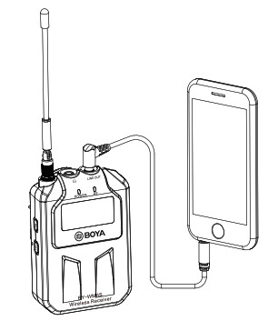
Connecting the transmitter and receiverUsing the microphone with smartphone, tablet, Mac or laptop with combo headphone/Mic jack.Receiver
- Mount receiver to smartphone, tablet, Mac or laptop.
- Using TRRS cable, plug the 3.5 mm connector (straight plug) into the audio jack of your smartphone.
- Insert the 90° plug of the connecting cable into the receiver“LINE OUT” jack.
- Insert earphone into receiver for monitoring sound if you need.
- Long press the power ON/OFF button (the “POWER” indicator will light in blue) Caution: Please do not mix up plug, for details, please refer to”What’s difference” on page 7.
![]() NOTE: Not all Android devices support external microphone when taking video, and you may need to download a third-party app and set up sound source as external microphone.
NOTE: Not all Android devices support external microphone when taking video, and you may need to download a third-party app and set up sound source as external microphone.
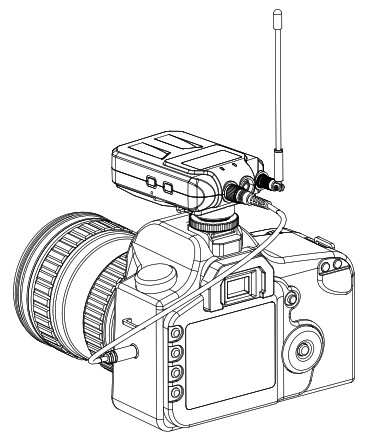
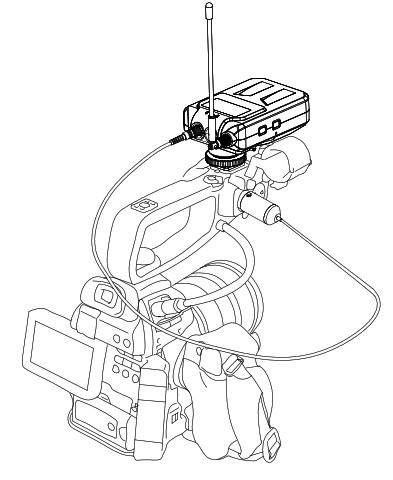
Using the microphone with cameras, camcorders, audio recorders and other audio/video recording devices.
Receiver
- Mount receiver to cameras, camcorders, audio recorders and other audio/video recording devices.
- Using TRS cable, plug the 3.5 mm connector into the audio jack of your camera.
- Insert the other end of the connecting cable into the receiver “LINE OUT” jack.
- Insert earphone into receiver for monitoring sound if you need.
- Long press the power ON/OFF button (the “POWER” indicator will light in blue) – Please make sure the antenna is oriented to the subject getting the best signal.
Using the microphone with camcorders and other XLR recording devices.Receiver
- Mount receiver to camcorders and other XLR audio/video recording devices.
- Using the supplied XLR cable, plug the terminal of XLR connector into the audio jack of your camcorder.
- Insert the other end of the connecting cable into the receiver “LINE OUT” jack.
- Insert earphone into receiverfor monitoring sound if you need.
- Press the power ON/OFF button ( the “POWER” indicator will light in blue) – Please make sure the antenna is oriented to the subject getting the best signal.
Using the microphone with camcorders and other XLR recording devices.Receiver1. Mount receiver to camcorders and other XLR audio/video recording devices.2. Using the supplied XLR cable, plug the terminal of XLR connector into the audio jack of your camcorder.3. Insert the other end of the connecting cable into the receiver“LINE OUT” jack.4. Insert earphone into receiver “ ” for monitoring sound if you need.5. Press the power ON/OFF button ( the “POWER” indicator will light in blue)– Please make sure the antenna is oriented to the subject getting the best signal.
Troubleshooting
If you have any problem using the BY-WM6S components, use the following checklist. If any problem persist, please consult our local dealer, or contact us directly.
| Status | Cause | Measure |
| The units does not turn on. | The batteries of BY-WM6S TX exhausted. | Use the supplied USB Type-C cable to charge it. |
| The batteries become drained quickly. | The BY-WM6S components is being used under extremely cold conditions. | The batteries drain quickly under extremely cold conditions. |
| The BY-WM6S Pro components is being used under extremely hot conditions. | The batteries drain quickly under extremely hot conditions. | |
| There is no sound. | There are in different channel on both transmitter and receiver. | Keep the same channel on both the transmitter and receiver. |
| There do not have a good connection with the lavalier. | Please try to reconnect it again. | |
| There do not have a well connection with the earphone. | Please try to reconnect it again. | |
| The sound is weak. | The input level of the receiver is low. | The input level of the transmitter is low. Adjust the audio output level on the transmitter. Keep this level as high as possible without distortion to reach best Sound and Noise Ratio. |
| Insert the lavalier incorrectly into the LINE IN jack. | Pull it out and reconnect to the MIC IN jack. | |
| There is distortion in the sound. | The input level of the receiver is inappropriate. | Adjust the audio output level on the transmitter. Keep this level as high as possible without distortion to reach best Sound and Noise Ratio. |
| There are in different channel on both transmitter and receiver. | Keep the same channel as both the transmitter and receiver. | |
| Headphones with a monaural mini jack is used. | Use the headphones with a stereo mini jack. | |
| The audio is noisy or distorted.This situation can include dropouts, white noise, bursts,pops and clicks. | RF interference | There can be a lot of RF interferenceoutdoors. Try moving indoors, where thereis less RF interference. Overhead telephone lines, fluorescent lighting, and metalfences can all cause interference. Turn off all nearby computers and mobile phones.” |
| RF signal is weak. | Make sure there is an unobstructed line of sight between the transmitterand the receiver.Keep in mind that your body, clothes, and onstage sets are possible obstructions.If there are obstructions, you may need to move closer. | |
| The input level on the camera, recorder, or mixer is too high. | Turn down the audio input level on your camera or recording devices.Turn down the audio output level on the receiver.Turn down the gain level on mixer. | |
| Too much ambience isbeing picked up. | When using an omnidirectional microphone like the oneincluded with this system, the microphone may be picking up too much ambience. | Make sure the microphone is as close as to the subject as possible. |
FCC STATEMENT:
This device complies with part 15 of the FCC Rules.Operation is subject to the following two conditions:(1) This device may not cause harmful interference.(2) This device must accept any interference received, including interference that may cause undesired operation.Warning: Changes or modifications to this unit not expressly approved by the party responsible for compliance could void the user’s authority to operate the equipment.NOTE: “This equipment has been tested and found to comply with the limits for a Class B digital device, pursuant to Part 15 of the FCC Rules. These limits are designed to provide reasonable protection against harmful interference in a residential installation. This equipment generates, uses and can radiate radio frequency energy and, if not installed and used in accordance with the instructions, may cause harmfulinterference to radio communications.However, there is no guarantee that interference will not occur in a particular installation. If this equipment does cause harmful interference to radio or television reception, which can be determined by turning the equipment off and on, the user is encouraged to try to correct the interference by one or more of the following measures: – Reorient or relocate the receiving antenna. – Increase the separation between the equipment and receiver. – Connect the equipment into an outlet on a circuit different from that towhich the receiver is connected. – Consult the dealer or an experienced radio/TV technician for help.
RF warning statement:The device has been evaluated to meet general RF exposure requirement. The device can be used in portable exposure condition without restriction.
Specifications
| Channel number | 48 |
| Oscillator type | PLL synthesizer |
| Carrier frequencies | 556.710-575.980MHz |
| Reference deviation | +/-5KHZ(-60dBV, 1KHz input) |
| Signal to noise ratio | 82dB or more |
| RF output power | 10mW |
| Distortion | 0.1% or less |
| Antenna | 1/4A wire antenna |
| Headphone output level | 30mW(16 ohm) |
| Receive sensitivity | -98dBm |
| Frequency respose | 40Hz to 18KHz (+/-3dB) |
| Reference audio input level | -60dBV (MIC input. 0dB attenuation) |
| Power requirement | Built-in Li-ion battery 1600mAh |
| DCSV (USB TYPE-C) | |
| Continuous time: 10 hours, Charging time: 2.5 hours (5V/1A) | |
| Dimensions | 60x24x90mm (2.4″x0.9″x3.5″) |
| Weight | 149g (5.3oz) |
[xyz-ips snippet=”download-snippet”]