
Braeburn® 7390 Wireless Remote Indoor Sensor Installer Guide
![]()
Please read all instructions before proceeding.
The wireless remote indoor sensor monitors temperature at a remote indoor location and transmits the temperature data wirelessly to the thermostat. The thermostat can be set to monitor temperature at the thermostat location, at the sensor location or by combining the temperature at the thermostat and the remote location(s). Up to 4 wireless indoor remote sensors can be connected.
Specifications
Operating Temperature: 40 – 99 °FStorage Temperature: 14 – 140 °FOperating Humidity: 5 – 95% RhControl Range: 45 – 90°FBattery Power: 3.0 Volt DCAccuracy: +/- 1°F
Blue LED Indicator
- 1 flash every 30 seconds: Normal operation
- 3 flashes every 10 minutes: Sending sensor data to thermostat
- 1 flash every 2 seconds: Sensor is in pairing mode
- Solid for 60 seconds: Successfully paired remote sensor
Red LED Indicator
- 3 flashes every 30 seconds: Low battery
- 1 flash every 10 seconds: Lost communication with thermostat
IMPORTANT: Before mounting the remote sensor, you should verify there is good wireless communication in the area you wish to mount it by first pairing it in that location. If you are having trouble pairing in that location, try moving the remote sensor to a location closer to the thermostat.
Pairing Remote Sensor(s)
See thermostat Installer Guide for additional information on pairing sensors.
- Enter the wireless setup mode on the thermostat you wish to pair with the remote sensor. Proceed until you see the word SENS in the display with a flashing
 symbol.
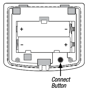
 - Make sure batteries are properly installed in the remote sensor and then press and hold the CONNECT button for 3 seconds.
- The remote sensor will enter pairing mode for 60 seconds. During this time the blue LED will flash once every 2 seconds.
- The thermostat will display IDS1, IDS2, IDS3 or IDS4 indicating that wireless remote indoor sensor 1, 2, 3 or 4 was successfully paired. The symbol will stop flashing and the blue LED on the remote sensor will turn on for 60 seconds.
- You can repeat this process to pair additional wireless remote sensors or exit the wireless setup mode on the thermostat.
NOTE: Sensors that have already been paired will appear in the thermostat display first, with a solid ![]() symbol.
symbol.
![]() A maximum of 4 wireless remote indoor sensors can be connected.A maximum of 4 wireless remote sensors total can be connected.
A maximum of 4 wireless remote indoor sensors can be connected.A maximum of 4 wireless remote sensors total can be connected.
Installation
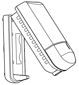
Remote sensors should be mounted on an interior wall, approximately 5 feet above the floor. For a more accurate temperature reading, keep the sensor away from heating and cooling vents and out of direct sunlight.
NOTE: Test location by pairing your thermostat before mounting (see section 2).
- Remove the front cover of the remote sensor. Using a small phillips blade screwdriver, loosen the screw located in the bottom center portion of the sensor housing. Gently swing the sensor housing in an upward motion and remove it from the top hinges.
- Place the small sub-base against the wall in the desired location and mark placement of the two mounting holes. Remove sub-base and carefully drill your marked areas with a 3/16” drill bit.
- If needed, gently tap supplied plastic anchors into the holes in the wall and fasten the remote sensor sub-base to the wall using the two supplied screws.
- Install the 2 supplied AA alkaline batteries into the sensor housing. The blue and red LED will each flash once to indicate the sensor has powered up successfully. If the red LED blinks 3 times every 30 seconds the batteries need to be replaced.
- Attach cover of remote sensor to the sub-base by engaging the hooks at the top and swinging down to a closed position. Reinstall the small screw to secure the sensor housing.
Replacing a Thermostat or a Sensor
Replacing a Thermostat – If you are replacing a thermostat that is paired with an existing wireless sensor, you will need to clear the remote sensor and pair it again with the newly installed thermostat.
- Install the new thermostat.
- On the wireless remote sensor you want to clear, press and hold the CONNECT button for 10 seconds until the red LED turns on solid.
- Release the CONNECT button and the blue and red LED will each flash once to indicate the sensor was successfully cleared.
- Pair the sensor again.
Replacing a Sensor – If you are replacing a wireless remote sensor that is paired with an existing thermostat, you will need to clear the thermostats remote sensor settings before pairing the new wireless remote sensor.
- Install the new wireless remote sensor.
- Thermostat remote sensor settings are cleared in the Installer Settings. Refer to the Installer Settings section of the thermostat Installer Guide.
- Once the remote sensor settings are cleared you will need to pair your new wireless remote sensor. You will also need to pair any other existing wireless remote sensors that were previously connected.
Communication Loss and Low Battery
Communication Loss – If communication between the remote sensor and thermostat is lost, the red LED on the remote sensor will begin to flash once every 10 seconds. The thermostat display will also indicate which wireless remote sensor has lost communication. The sensor will attempt to reconnect to the thermostat several times automatically.
NOTE: To reconnect manually, press and hold the CONNECT button for 3 seconds.
Remote Sensor Low Battery – If the batteries in a wireless remote sensor are low, the red LED will flash 3 times every 30 seconds. The thermostat display will also indicate which wireless remote sensor has a low battery. Replace the remote sensor batteries as soon as possible.
NOTE: After replacing batteries, allow up to 15 minutes for the wireless connection to re-establish.
MPEG LA License Agreement
THIS PRODUCT IS LICENSED UNDER THE WIRELESS NETWORK PATENT PORTFOLIO LICENSE FOR USE BY A CONSUMER OR OTHER USES FOR WHICH THERE IS NO REMUNERATION. ANY OTHER USE OF THIS PRODUCT IN ANY MANNER IS NOT LICENSED AND IS EXPRESSLY PROHIBITED WITHOUT A LICENSE UNDER APPLICABLE PATENTS IN THE WIRELESS NETWORK PATENT PORTFOLIO, WHICH LICENSE IS AVAILABLE FROM MPEG LA, LLC, 4600 S. ULSTER ST., SUITE 400, DENVER, COLORADO 80237 U.S.A. SEE HTTP://WWW.MPEGLA.COM.
This equipment has been tested and found to comply with the limits for a Class B digital device, pursuant to Part 15 of the FCC Rules. These limits are designed to provide reasonable protection against harmful interference in a residential installation. This equipment generates uses and can radiate radio frequency energy and, if not installed and used in accordance with the instructions, may cause harmful interference to radio communications. However, there is no guarantee that interference will not occur in a particular installation. If this equipment does cause harmful interference to radio or television reception, which can be determined by turning the equipment off and on, the user is encouraged to try to correct the interference by one or more of the following measures:
- Reorient or relocate the receiving antenna.
- Increase the separation between the equipment and receiver.
- Connect the equipment into an outlet on a circuit different from that to which the receiver is connected.
- Consult the dealer or an experienced radio/TV technician for help.
Changes or modifications not expressly approved by the party responsible for compliance could void the user’s authority to operate the equipment. This device complies with part 15 of the FCC Rules. Operation is subject to the following two conditions: (1) This device may not cause harmful interference, and (2) this device must accept any interference received, including interference that may cause undesired operation.
This device complies with Industry Canada’s licence-exempt RSSs. Operation is subject to the following two conditions:
(1) This device may not cause interference; and(2) This device must accept any interference, including interference that may cause undesired operation of the device.
Limited Warranty
When installed by a professional contractor, this product is backed by a 5 year limited warranty. Limitations apply. For limitations, terms and conditions, you may obtain a full copy of this warranty:
- Visit us online: www.braeburnonline.com/warranty
- Write us: Braeburn Systems LLC2215 Cornell AvenueMontgomery, IL 60538
Braeburn Systems LLC2215 Cornell Avenue · Montgomery, IL 60538Technical Assistance: www.braeburnonline.com844-BLU-LINK (844-258-5465) (U.S.)630-844-1968 (Outside the U.S.)©2016 Braeburn Systems LLC · All Rights Reserved · Made in China.
References
[xyz-ips snippet=”download-snippet”]