Weather Station · Wetterstation ·Colour Weather Center 5in1Instruction manual
Visit our website via the following QR Code or web link to find further information on this product or the available translations of these instructions.
 |
|
|
| www.bresser.de/P7002525 | www.bresser.de/P7902525 | www.bresser.de/P7802525 |
GARANTIE

Imprint
Bresser GmbHGutenbergstr. 246414 RhedeGermanywww.bresser.deFor any warranty claims or service inquiries, please refer to the information on “Warranty” and “Service” in this documentation. We apologize for any inconvenience caused by the fact that we cannot process inquiries or submissions sent directly to the manufacturer’s address.Errors and technical changes excepted.©2021 Bresser GmbH All rights reserved.The reproduction of this documentation – even in extracts – in any form (e.g. photocopy, print, etc.) aswell as the use and distribution by means of electronic systems (e.g. image file, website, etc.)without the prior written permission of the manufacturer is prohibited.The designations and brand names of the respective companies used in this documentation are generally protected by trade, trademark and/or patent law in Germany, the European Union, and/or other countries.
Validity note
This documentation is valid for the products with the following article numbers: 7002525 7902525 7802525Manual version: 0621Manual designation:Manual_7002525-7902525-7802525_Colour-Weather-Center-5in1_en-de_BRESSER_v062021aAlways provide information when requesting service.
Features
- Precipitation measurement
- Measurement of wind speed
- Wind direction measurement
- DCF radio clock reception and display
- Alarm with snooze function
- Outdoor temperature alarm (frost warning)
- Outdoor temperature (in °C or °F)
- Indoor temperature (in °C or °F)
- Humidity indoor/outdoor
- Air pressure
- Weather index: “Feels like”, Windchill, Heat index, Dew point
- Beaufort scale
- The lowest and highest value display
- Max/min values storage
- Weather Forecast (12~24 hours)
- Moon phases
- Colour display
- Backlight
About this Instruction Manual
![]() NOTICE
NOTICE
These operating instructions are to be considered a component of the device.Read the safety instructions and the operating manual carefully before using this device.Keep this instruction manual in a safe place for future reference. When the device is sold or given to someone else, the instruction manual must be provided to the new owner/user of the product.
Parts overview base station
![]()
Illustration 1: All parts of the base station
- ALARM/SNOOZE button (snooze function)
- Colour display
- HISTORY key (retrieve measured values from the last 24 hours)
- RAIN button (displays various precipitation values)
- BARO key (display of different air pressure
- MAX/MIN key (change between maximum, values) inimum or current value display)
- INDEX key (display change between felt temperature, dew point, heat index, and wind chill factor)
- WIND key (change between average and current wind gust)
- Stand, removable
- Wall bracket
- ALERT key (e.g. set temperature alarm)
- ALARM button (wake-up call setting)
- CLOCK SET key (manual time setting)
- HI/LO/AUTO switch (display brightness)
- °C/°F key (display changes between °C and °F)
- RCC Button (Initiate time signal reception)
- Battery compartment (cover)
- USB power socket for mains adapter
- DOWN key (value change downwards)
- UP key (value change upwards)
- RESET button (reset all settings)
- SENSOR button (sensor search)
- AC adapter with DC plug (USB)
Scope of delivery
The base station (A), power adapter (B), stand (C), multifunctional outdoor sensor (D), mounting rod (E), mounting shoe (F), pipe clamp (G), screws, instruction manual
Also required (not included in delivery): 3 x 1.5V batteries type AA/LR6 (outdoor sensor)Backup battery (not included in delivery): 1 piece of 3V battery type CR2032 (base station)
Screen display
![]()
- Internal temperature
- Indoor humidity
- Comfort indicator (climate)
- Outdoor temperature
- Outdoor humidity
- Battery level indicator Outdoor sensor
- Received signal strength Outdoor sensor
- Outdoor temperature alarm active (HI/LO)
- Wind direction
- Wind direction indicator
- Wind direction indicator (of the last 5 minutes)
- Wind speeds
- Wind alarm active (HI)
- Wind speed value: mean value (AVERAGE) or last gust (GUST)
- Wind speed value (mph, m/s, km/h, knot)
- Beaufort scale for wind force classification
- INDEX Display change between: feels like, wind chill factor, heat index and dew point
- Current time
- The symbol for active daylight saving time (DST)
- The symbol for the radio signal
- Wake-up call active
- Moon phase
- Day of the week
- Weather forecast
- Display change: Relative or absolute air pressure
- Air pressure (hPa, inHg or mmHg)
- Air pressure history (24 hours)
- History of air pressure values
- Precipitation alarm active (HI/LO)
- Precipitation quantity
- Precipitation history (5 days)
- Timing information
Before commissioning
 NOTICEAvoid connection faults!In order to avoid connection problems between the devices, the following points must be observed during commissioning.
- Place the base unit (receiver) and sensor (transmitter) as close together as possible.
- Connect the power supply to the base unit and wait until the indoor temperature is displayed.
- Establish a power supply for the sensor.
- Set up/operate the base unit and sensor within the effective transmission range.
- Make sure that the base unit and the radio sensor are set to the same channel.
When changing the batteries, always remove the batteries in both the base unit and the sensor and reinsert them in the correct order so that the radio connection can be re-established. If one of the two devices is operated via a mains power connection, the power connection for this device must also be disconnected briefly when changing the battery. If, for example, only the batteries in the sensor are replaced, the signal cannot be received or can no longer be received correctly.Note that the actual range depends on the building materials used in the building and the position of the base unit and outdoor sensor. External influences (various radio transmitters and other sources of interference) can greatly reduce the possible range. In such cases, we recommend finding other locations for both the base unit and the outdoor sensor. Sometimes a shift of just a few centimeters is enough!
Establish power supply
Base unit
- Insert the DC plug into the connection socket on the base unit.
- Insert the Euro plug into the mains power socket.
- The device is powered on directly.
Installing the backup battery:
- Remove the battery compartment cover.
- Insert the battery into the battery compartment. Make sure that the battery terminals are correctly aligned (+/-).
- Replace the battery compartment cover.Wireless sensor
- Remove the screw on the battery compartment cover with a suitable Phillips screwdriver and remove the battery compartment cover.
- Insert 2 x AA-size batteries into the battery compartment. Make sure that the battery terminals are correctly aligned (+/-).
- Replace and screw on the battery compartment cover.
Attaching rubber linings
Attach the supplied self-adhesive rubber pads to the clamps as shown to ensure a firmer fitting of the mounting rod.
Assembling and installing the multifunctional remote sensor
Depending on the desired location, the wireless sensor can be mounted in different ways.
NOTICE! During installation, always ensure that the upper part of the wind vane is at least 1.5 meters above the ground. Ensure an absolutely horizontal position when mounting using the circular level in the sensor head. The wind vane must always face north.
Assembly on a vertical or horizontal wooden element
- Slide one end of the assembly bar into the aperture below the sensor head.
- Slide one screw through the borehole and put it on the nut on the opposite side. Tighten the screw connection by hand.
- Depending on the desired orientation, slide the opposite end of the assembly bar into the aperture for vertical or horizontal mounting of the assembly base.
- Slide another screw through the borehole of the assembly base and put it on the nut on the opposite side. Tighten the screw connection by hand.Place the assembly base with its bottom site first on a wooden element. Use 4 wood screws to tighten it.Assembly on a vertical or horizontal tube
- Repeat steps 1 to 4 as before.
- Place the assembly base with its bottom site first on the tube. Push the tube bracket against the tube from the opposite site.
- Slide 4 screws through the bore holes of the assembly base and through the bore holes of the tube bracket on the other site.
- Put on the 4 nuts and tighten the screw connection by hand.
Signal transmission
The base station will automatically connect to the outdoor sensor. If the battery is changed, the connection must be made manually by pressing the [SENSOR] button at the base station and then pressing the [RESET] button on the sensor with a pointed object to manually search for the sensor. When the connection is successful, the sensor signal strength indicator will be shown on the display.
Connection status display:
| Connection status | Screen display |
| Good signal | Reception symbol |
| Searching for a sensor | Reception symbol flashes |
| No signal for 48 hours | Er’ (Error) is shown |
| Sensor low battery status, good signal | Battery symbol is shown |
Automatic time setting
After the power is restored, the unit automatically searches for the radio signal. It takes approximately 3-8 minutes for this process to complete.If the radio signal is received correctly, the date and time are set automatically and the reception symbol is displayed.
NOTICE! During radio signal reception, the backlight is set to dimmed mode and returned to normal mode when signal reception is complete.If no radio signal is received, proceed as follows:
- Press the RCC button on the base unit for approx. 8 seconds to deactivate reception of the radio signal (the display shows “OFF”).
- Press the RCC button on the base unit for approx. 8 seconds to activate reception of the radio signal (“ON” appears in the display). Reception is now initialized again.
- If no radio signal is still received, the time setting must be made manually.
Manual time setting
To set the time/date manually, first, disable the reception of the time signal by pressing the RCC button for about 8 seconds.
- Press the CLOCK-SET button for approx. 3 seconds to enter the time setting mode.
- Digits to be set are flashing.
- Press the UP or DOWN button to change the value.
- Press the CLOCK-SET button to confirm the entry and move to the next setting.
- Settings order: 12/24-hour mode > Hours > Minutes > Seconds > Year > M> Day > Time offset >Language > Daylight saving time Auto/off
- Finally, press the CLOCK-SET button to save the settings and exit the setting mode.
Time zone setting
To set a different time zone, proceed as follows:
- Press the CLOCK-SET button for approx. 3 seconds to enter the time setting mode.
- Press the CLOCK-SET button several times until the display shows 00 Hr time offset.
- Press UP or DOWN button to select the desired time deviation in hours (-23 up to +23 hours).
- Press the CLOCK-SET button for approx. 3 seconds to confirm the selected time deviation.
Setting Daylight Saving Time (DST)
To set a different time zone, proceed as follows:
- Press the TIME button for about 3 seconds to enter the time setting mode.
- Press the TIME button repeatedly until the daylight saving time (DST) setting flashes on the display.
- Press the UP or DOWN button to select between AUTO (summer time on) and OFF (summer time off).
- Press the TIME button for about 3 seconds to confirm the setting.
Alarm setting
Turn on/off Alarm clock (and Ice Alert function)
- Press the ALARM button to show the alarm time.
- Press the ALARM button again to activate the alarm.
- Press the ALARM button one more time to activate the alarm with an ice alert.
- With an activated ice alert, the alarm will sound 30 minutes earlier if the outside temperature is below -3°C.
- To disable the alarm and ice alert, press the ALARM button until the alarm icons disappear. Set Alarm time
- Press and hold the ALARM button for approx. 3 seconds to enter the alarm time setting mode.
- Digits to be set are flashing.
- Press the UP or DOWN button to change the value.
- Press the ALARM button to confirm and continue to the next setting.
- Settings order: Hours > Minutes
- Finally, press the ALARM button to save the settings and exit the setting mode.
Snooze function
- When the alarm sound starts, press the ALARM/SNOOZE button to activate the Snooze function.The Alarm will sound again after 5 minutes.
- When the alarm sound starts, press the ALARM button or press and hold the ALARM/SNOOZE button for approx. 3 seconds, to stop the alarm.
- The alarm will be turned off automatically if no button is pressed within 2 minutes.
Receiving measurements automatically
Once power is restored, the base station will begin to display indoor readings and the first readings received from the outdoor sensor will be displayed within approximately 3 minutes of commissioning.If no signal is received, proceed as follows:Press the SENSOR button for approx. 2 seconds to initiate the reception of the measured values again.
Rainfall
The amount of precipitation is displayed on the base station in millimeters or inches that has accumulated over a period of time, based on the current precipitation rate.

Select display modePress the RAIN key repeatedly until the desired time period is shown on the display:
| RATE | Current precipitation of the last hour |
| DAILY | Total precipitation of the current day, measured from midnight |
| WEEKLY | Total precipitation of the current week |
| MONTHLY | Total precipitation of the current month |
Select measurement unit (millimeters or inches)
- Press the RAIN key for about 3 seconds to enter unit setting.
- Press the UP or DOWN key to toggle between mm (millimeters) and in (inches).
- Finally, press the RAIN key to save the settings and exit settings mode.
NOTICE! The readings are automatically updated every 6 minutes.
HI/LO Alert
HI/LO alerts are used to alert you of certain weather conditions. Once activated, an alarm sound is triggered and the alert icon flashes as soon as a set value is reached. Supported areas and alarm types:
| Area | Type of alert available |
| Indoor temperature | HI AL / LO AL |
| Indoor humidity | HI AL / LO AL |
| Outdoor temperature | HI AL / LO AL |
| Outdoor humidity | HI AL / LO AL |
| Rainfall (daily) | HI AL* |
| Wind speed | HI AL |
HI AL = High alert / LO AL = Low alert*Daily rainfall since midnight
HI/LO alert setting
- Press the ALERT button until the desired area is selected.
- Press the UP or DOWN button to change the value.
- Press the ALERT button to confirm and continue to the next setting.Enable/Disable HI/LO Alert
- Press ALERT button until the desired area is selected.
- Press ALARM button, to activate the alarm.
- Press ALERT button to confirm and continue to the next setting.Note:
- The unit will automatically exit setting mode in 5 seconds if no button is pressed.
- When ALERT alarm is on, the area and type of alarm that triggered the alarm will be flashing and the alarm will sound for 2 minutes.
- Press SNOOZE/LIGHT button when an alarm sounds to interrupt the alarm. The alarm will then start again after 2 minutes.Data clearing
- Press and hold HISTORY button for approx. 3 seconds.
- Press UP or DOWN button to choose YES or NO.
- Press HISTORY button to confirm. This will clear out any rainfall data recorded before.
Clima indication (indoor)
| 1 too cold | 2 comfortable |
| 3 too warm |
The climate indication is a pictorial indication based on indoor air temperature and humidity in an attempt to determine comfort level.
Note:
- Comfort indication can vary under the same temperature, depending on the humidity.
- There is no comfort indication when the temperature is below 0° C (32° F) or over 60° C (140° F)
Data clearing
During the installation of the outdoor sensor, the sensor could have been triggered, resulting in erroneous rainfall and wind measurements. After the installation user may clear all the erroneous data from the main unit without a need to reset the clock and re-establish pairing. Simply press and hold the HISTORY button for 10 seconds. This will clear out any data recorded before.
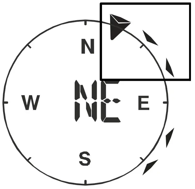
Pointing the sensor to the south
The sensor is calibrated to be pointing to the North by default. However, in some cases, users may wish to install the product with the arrow pointing towards the South, especially for people living in the Southern hemisphere (e.g. Australia, New Zealand)
| 1 Northern hemisphere | 1 Northern hemisphere |
- First, install the outdoor sensor with its arrow pointing to the south. Please refer to the “Installation” chapter for mounting details.
- Press and hold the WIND button for approx. 8 seconds until the upper part (northern hemisphere) of the compass rose is blinking.
- Press the UP or DOWN button to change to the lower part (southern hemisphere).
- Press the WIND button to confirm and exit.
Note:Changing the hempisphere setting will automatically switch the direction of the moon phase on the display.
Moon phases
In the Northern hemisphere, the moon waxes from the right. Hence the sun-lit area of the moon moves from right to left in the Northern hemisphere, while in the Southern hemisphere, it moves from left to right. Below are the 2 tables which illustrate how the moon will appear on the main unit.
Illustration 3: (A) Northern hemisphere, (B) Southern hemisphere
| 1 New moon | 2 Waxing crescent |
| 3 First quarter | 4 Waxing gibbous |
| 5 Full moon | 6 Waning gibbous |
| 7 Third quarter | 8 Waning crescent |
Weather trend
A weather trend for the next 12-24 hours is calculated from the measured values and displayed graphically as follows:

| 1 Sunny | 2 Partly cloudy |
| 3 Cloudy | 4 Rain |
| 5 Rain/storm | 6 Snow |
Note:
- The accuracy of a pressure-based weather forecast is about 70% to 75%.
- The weather forecast is intended for the next 12 hours and does not necessarily reflect the current situation.
- The snow weather forecast is not based on air pressure, but on the outdoor temperature. When the outdoor temperature is below -3°C (26°F), the snow symbol appears on the LCD display.
Barometric / Atmospheric Pressure
Atmospheric pressure (hereinafter referred to as “air pressure”) is the pressure at any place on earth caused by the weight of the layer of air above it. Air pressure is proportional to average pressure and decreases gradually with altitude. Meteorologists use barometers to measure air pressure. Because the weather is highly dependent on changes in air pressure, it is possible to make a weather forecast from the measured changes in air pressure.
In normal display mode, press the BARO button repeatedly to display the desired unit (hPa, inHg or mmHg).
Set relative atmospheric pressure
- Find out the relative air pressure value for your location (or as close to it as possible) through thelocal weather service, the Internet or other sources.
- Press the BARO button for approx. 3 seconds until ABS or REL flashes.
- Press the UP or DOWN key until REL flashes.
- Press the BARO button to move to the next setting value.
- Press the UP or DOWN key to change the REL value (according to the researched value).
- Finally, press the CLOCK-SET button to save the settings and exit the setting mode.• NOTICE! ABS: Absolute air pressure at your current location• NOTICE! REL: Relative air pressure based on sea level (N.N.)• NOTICE! The default relative air pressure value is 1013 bar/hPa (29.91 inHg), which is relative to the average air pressure value.• NOTICE! If the value for the relative air pressure is changed, the weather displays also change as a result.• NOTICE! The built-in barometer registers changes in absolute air pressure caused by the environment. Based on the collected data, a forecast for the weather conditions in the next 12 hours can be made. The weather indicators change according to the determined absolute air pressure after only one hour of operation.•NOTICE! The relative air pressure is based on sea level, but it also changes with changes in absolute air pressure after one hour of operation.
Wind speed and direction
Reading the wind direction
| Wind direction indicator | Meaning |
| Real-time wind direction | |
| Wind directions appeared in the last 5 minutes (max. 6) |
Select display modePress the WIND button several times until the desired rate is displayed:
- AVERAGE: average of all wind speed numbers recorded in the previous 30 seconds
- GUST: highest wind speed (gust) recorded from last reading
The wind level provides a quick reference on the wind condition and is indicated by a series of text icons:
| Wind level | LIGHT | MODERATE | STRONG | STORM |
| Speed | 1 – 19 km/h | 20 – 49 km/h | 50 – 88 km/h | > 88 km/h |
Select wind speed unit
- Press the WIND button for approx. 3 seconds to enter the setting mode.
- Press the UP or DOWN button to change the unit between mph (miles per hour), m/s (miles per second), km/h (kilometer per hour) or knots.
- Press the WIND button to save the settings and exit the setting mode.
Beaufort scale
The Beaufort scale is an international scale of wind velocities from 0 (calm) to 12 (Hurricane force).
|
Beaufort number |
Description |
Speed |
| 0 | calm | < 1 km/h 1 < 1 mph< 1 knots I < 0.3 m/s |
| 1 | light air | 1.1-5.5 km/h 1 1-3 mph |
| 1-3 knots 1 0.3-1.5 m/s | ||
| 2 | light breeze | 5.6-11 km/h 1 4-7 mph |
| 1-3 knots 1 0.3-1.5 m/s | ||
| 3 | gentle breeze | 12-19 km/h 1 8-12 mph |
| 7-10 knots I 3.5-5.4 m/s | ||
| 4 | moderate breeze | 20-28 km/h 1 13-17 mph |
| 11-16 knots 1 5.5-7.9 m/s | ||
| 5 | fresh breeze | 29-38 km/h 1 18-24 mph |
| 17-21 knots 1 8.0-10.7 m/s | ||
| 6 | strong gale | 39-49 km/h 1 25-30 mph |
| 22-27 knots 1 10.8-13.8 m/s | ||
| 7 | high wind | 50-61 km/h 1 31-38 mph |
| 28-33 knots 1 13.9-17.1 m/s | ||
| 8 | gale | 62-74 km/h 1 39-46 mph |
| 34-40 knots 1 17.2-20.7 m/s | ||
| 9 | strong gale | 75-88 km/h 1 47-54 mph |
| 41-47 knots I 20.8-24.4 m/s | ||
| 10 | storm | 89-102 km/h 1 55-63 mph |
| 48-55 knots I 24.5-28.4 m/s | ||
| 11 | violent storm | 103-117 km/h 1 64-73 mph |
| 56-63 knots I 28.5-32.6 m/s | ||
| 12 | hurricane force | > 118 I > 74 mph |
| > 64 knots 1 32.7 m/s |
Wind chill factor
Press the INDEX button several times until WIND CHILL is displayed.Note:
The wind chill factor is based on the common effects of temperature and wind speed. The displayed wind chill is calculated solely from temperature and wind speed and is measured by the outdoor sensor.
Temperature display
Move the °C/°F switch to toggle between °C and °F temperature display.When temperatures of -40° C or below are reached, the information “LO” is output for the respective range, when temperatures of over 70° C or above are reached, the information “HI” is output. The measurable temperature range has been exceeded or fallen below.When returning to a measurable temperature range, the appropriate temperature is displayed again.
Feels like temperaturePress the INDEX button repeatedly until FEELS LIKE appears on the display.Note:The feels like temperature indicates the temperature value according to the personal temperature perception.
Heat index
Press the INDEX button several times until HEAT INDEX is displayed.
| Heat index | Warning | Meaning |
| > 55° C | Extreme danger | Strong risk of dehydration/sun stroke |
| (> 130° F) | ||
| 41° C – 54° C | Danger | Heat exhaustion likely |
| (106° F – 129° F) | ||
| 33° C – 40° C | Extreme caution | Possibility of dehydration |
| (91° F – 105° F) | ||
| 27° C – 32° C | Caution | Possibility of heat exhaustion |
| (80° F – 90° F) |
Notice:The perceived temperature is based on the common effects of temperature and humidity. The heat index is only calculated when the room temperature is at 27° (80° F) or higher. The displayed perceived temperature is calculated solely from temperature and humidity and is measured by the outdoor sensor.
Dew point
Press the INDEX button several times until DEW POINT is displayed.Note:The dew point is the temperature below which the water vapor in air at constant barometric pressure condenses into liquid water at the same rate at which it evaporates. The condensed water is called dew when it forms on a solid surface. The dewpoint temperature is calculated from the indoor temperature and humidity measured at the main unit.
History record for the past 24 hours
The base station automatically records and displays data of the past 24 hours.
- Press the HISTORY button to check history records of the last hour.
- Press the HISTORY button several times to display the history records of the hours 2,3,4,5 ……
MAX/MIN Weather data
The base station preserves the MAX/MIN weather data records until the next manual reset. To retrieve the data:
- Press MAX/MIN button several times to display the stored values one after another.
- Display order: Outdoor max temperature > Outdoor min temperature > Outdoor max humidity > Outdoor min humidity > Indoor max temperature > Indoor min temperature > Indoor max humidity > Indoor min humidity > Outdoor max wind chill > Outdoor min wind chill > Outdoor max heat index > Outdoor min heat index > max dew point > min dew point > max pressure > min pressure > max average > max gust > max rainfall
- Press MAX/MIN button for approx. 2 seconds to delete all saved values.
Display brightness regulation
- Move the[HI/LO/AUTO] switch to change the brightness of the display. The brightness is automatically adjusted to the next level. Brightness level order: brighter backlight[HI] > dimmer backlight[LO] > automatic[AUTO]
- [AUTO] automatically adjusts the brightness according to the environment.
Technical data
Base unit
| Power supply | 5V DC 600mA USB power plugBackup: 1x CR2032 |
| Temperature unit | °C/°F |
| Time display | HH:MM: SS/weekday |
| Time format | 12 or 24 hours |
| Calendar display | DD/MM |
| Time signal | |
| DAYLIGHT SAVING TIME (DST) | AUTO / OFF |
| Dimensions | 118 x 192.5 x 21 mm (W x H x D) |
| Weight (incl. batteries) | 260 g |
Multisensor
| Batteries | 3x AA, 1.5V |
| Maximum number of sensors | 1x wireless multisensor |
| RF transmission frequency | 868 MHz |
| RF transmission range | 150 m |
| Maximum radio-frequency power | < 25mW |
| Temperature measuring range | from -40°C to 60°C (from -40°F to 140°F) |
| Barometer measuring range | 540 to 1100hPa |
| Humidity measuring range | 1 ~ 20% RH ± 6.5% RH @ 25°C (77°F) 21 ~ 80% RH ± 3.5% RH @ 25°C (77°F) 81 ~ 99% RH ± 6.5% RH @ 25°C (77°F) |
| Humidity resolution | 1% HR |
| Precipitation measuring range | From 0 to 9999 mm (from 0 to 393.7 inch) |
| Wind speed measuring range | From 0 to 112 mph, 50 m/s, 180km/h, 97 knots |
| Dimensions | 343.5 x 393.5 x 136 mm (W x H x D) |
| Weight (incl. batteries) | 673 g |
EC declaration of conformity
 |
A “Declaration of conformity” in accordance with the applicable directives and corresponding standards has been prepared by Bresser GmbH. The full text of the EC declaration of conformity is available at the following Internet address: http://www.bresser.de/download/7002525/CE/7002525_7902525_7802525_CE.pdf |
UKCA Declaration of Conformity
| Bresser GmbH has issued a “Declaration of Conformity” in accordance with applicable guidelines and corresponding standards. The full text of the UKCA declaration of conformity is available at the following internet address: http://www.bresser.de/download/7002525/CE/7002525_7902525_7802525_UKCA.pdf | |
| Bresser UK Ltd. • Suite 3G, Eden House, Enterprise Way, Edenbridge, Kent TN8 6Hf, Great Britain |
Warranty
The regular warranty period is 5 years and starts on the day of purchase. For full warranty terms and services, please visit www.bresser.de/warranty_terms.
Disposal
| Dispose of the packaging materials properly, according to their type, such as paper or cardboard. Contact your local waste disposal service or environmental authority forinformation on the proper disposal. | |
| Do not dispose of electronic devices in the household garbage!According to the European Directive 2012/19/EU on Waste Electrical and Electronic Equipment and its transposition into national law, used electrical equipment must be collected separately and recycled in an environmentally sound manner. | |
 |
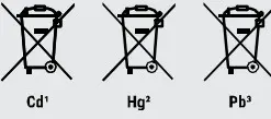
Batteries and rechargeable batteries must not be disposed of with household waste. You are legally obliged to return used batteries and accumulators and can return the batteries after use either in our sales outlet or in the immediate vicinity (e.g. in the trade or in municipal collection points) free of charge. Batteries and accumulators are marked with a crossed-out dustbin and the chemical symbol of the pollutant, “Cd” stands for cadmium, “Hg” stands for mercury and “Pb” stands for lead. |
Service
Please contact the service center first for any questions regarding the product or claims, preferably by e-mail.e-mail: [email protected]Telephone*: +44 1342 837 098BRESSER UK LtdCustomer SupportSuite 3G, Eden HouseEnterprise WayEdenbridge, Kent TN8 6HFUnited Kingdom* Number charged at local rates in the UK (the amount you will be charged per phone call will depend on the tariff of your phone provider); calls from abroad will involve higher costs.
Bresser GmbHGutenbergstraße 246414 Rhede · Germanywww.bresser.de
@BresserEurope
report this adReferences
index · powered by h5ai 0.26.1 (http://larsjung.de/h5ai/)
This domain was successfully registered for the highest bidder in our weekly auction.
bresser.de/garantiebedingungen
Bresser | BRESSER Wetter Center 5-in-1 Beaufort mit Farbdisplay | Expand Your Horizon
konsoleH :: Login
disponibles.IT
bresser.de/warranty_terms
Bresser | BRESSER zusätzliche Basisstation für 7002525 Beaufort Wetter-Center 5-in-1 | Expand Your Horizon
Bresser | Startseite | Expand Your Horizon mit BRESSER
[xyz-ips snippet=”download-snippet”]