BRESSER 7002530 Weather Station Professional Rain Gauge Instruction Manual
Imprint (German)
Bresser GmbHGutenbergstr. 246414 RhedeGermanywww.bresser.de
For any warranty claims or service enquiries, please refer to the information on “Warranty” and “Service” in this documentation. We apologize for any inconvenience caused by the fact that we cannot process enquiries or submissions sent directly to the manufacturer’s address.
Errors and technical changes excepted.
© 2021 Bresser GmbH
All rights reserved.
The reproduction of this documentation – even in extracts – in any form (e.g. photocopy, print, etc.) as well as the use and distribution by means of electronic systems (e.g. image file, website, etc.) without the prior written permission of the manufacturer is prohibited.
The designations and brand names of the respective companies used in this documentation are generally protected by trade, trademark and/or patent law in Germany, the European Union and/or other countries.
Validity note
This documentation is valid for the products with the following article numbers: 7002530Manual version: 0421Manual designation:Manual_7002530-7002533_Professional-Rain-Gauge_de-en_BRESSER_v042021a Always provide information when requesting service.
Features
- Measurement of Rainfall
- Radio-controlled clock with DCF signal reception and display
- Alarm with snooze function
- Outdoor temperature alarm (frost warning)
- Outdoor temperature (in °C or °F)
- Indoor temperature (in °C or °F)
- Indoor humidity
- Histogram
- SINCE function to display the total rainfall from a customized point in time.
- Highest and lowest value display
- Max-/Min Memory
- Backlight
About this Instruction Manual
NOTICE
These operating instructions are to be considered a component of the device.Read the safety instructions and the operating manual carefully before using this device. Keep this instruction manual in a safe place for future reference. When the device is sold or given to someone else, the instruction manual must be provided to the new owner/user of the product.
General safety instructions
![]() DANGER
DANGER
![]() Danger of suffocation!
Danger of suffocation!
Improper use of this product may result in suffocation, especially for children. It is therefore imperative that you observe the following safety information.
- Keep packaging materials (plastic bags, rubber bands, etc.) away from children! There is a danger of choking!
- This product contains small parts that can be swallowed by children! Choking hazard!
![]() Risk of an electric shock!
Risk of an electric shock!
This device contains electronic parts that are powered by a power source (AC adapter and/or batteries). Improper use of this product may result in electric shock. Electric shock can cause serious or fatal injuries. It is therefore imperative that you observe the following safety information.
- Never leave children unattended when handling the device! Follow the instructions carefully and do not attempt to power this device with anything other than power sources recommended in this instruction manual, otherwise there is a danger of an electric shock!
![]() Explosion hazard!
Explosion hazard!
Improper use of this product may result in fire. It is essential that you observe the following safety information in order to avoid fires.
- Do not expose the device to high temperatures. Use only the recommended batteries. Do not short-circuit the device or batteries, or throw them into a fire! Excessive heat or improper handling could trigger a short-circuit, a fire or an explosion!
NOTICE
![]() Danger of material damage!
Danger of material damage!
Improper handling may result in damage to the unit and/or accessories. Therefore, use the device only in accordance with the following safety information.
- Do not disassemble the device! In the event of a defect, please contact your dealer. They will contact the Service Center and can arrange the return of this device for repair if necessary.
- Do not immerse the unit in water!
- Do not expose the device to impacts, vibrations, dust, constant high temperatures or excessive humidity. This can result in malfunctions, short-circuits or damage to the batteries and components.
- Use only the recommended batteries. Always replace weak or empty batteries with a new, complete set of batteries at full capacity. Do not use batteries from different brands or types or with different capacities. Remove batteries from the device if it is not to be used for a longer period of time!
 Risk of voltage damage!
The manufacturer is not liable for damage related to improperly installed batteries!
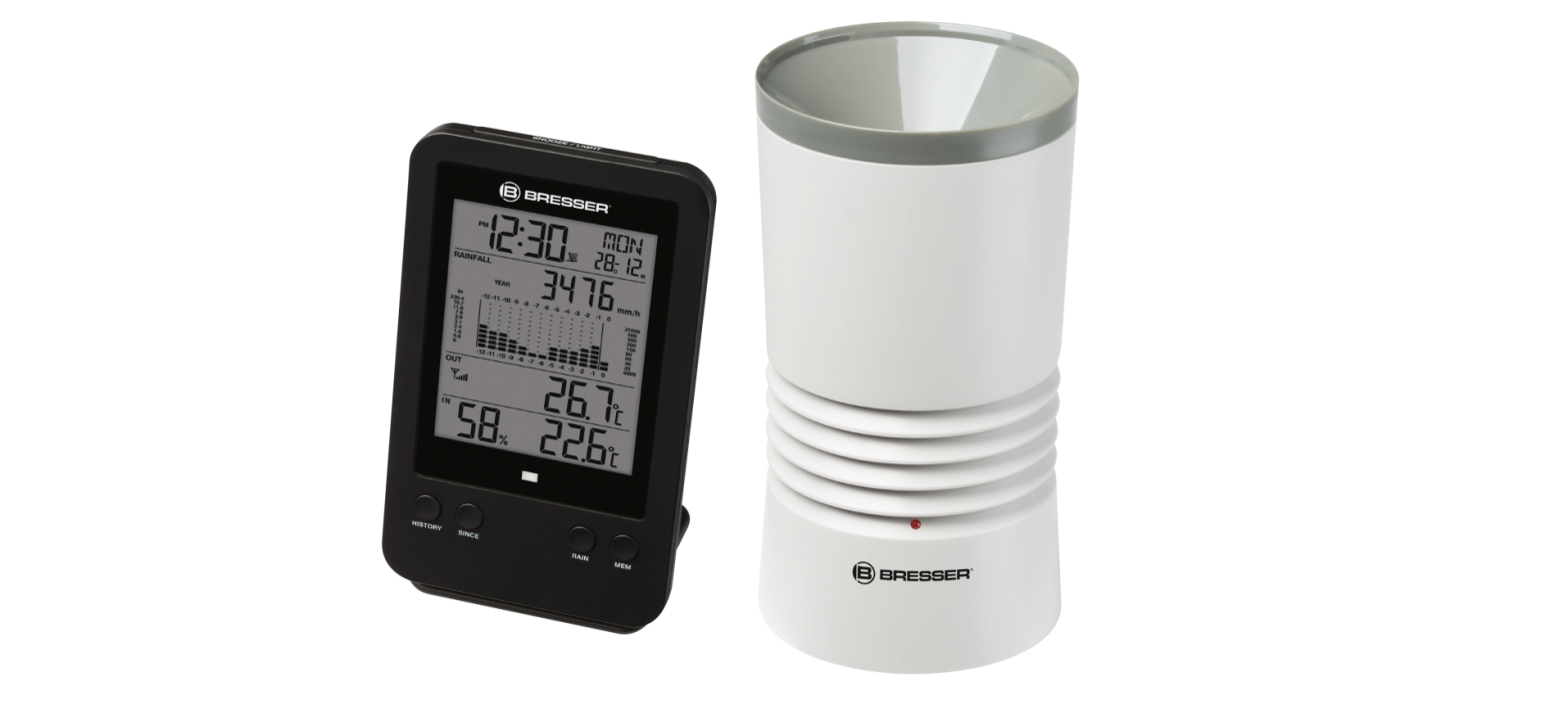
Parts overview Base station
- LCD display with backlight
- Alert LED indicator (blinks when the alarm is on)
- HISTORY button
- SINCE button (Total Rainfall)
- RAIN button (Rainfall)
- MEM button (MAX/MIN)

- CLOCK button
- ALARM button
- ALERT button
- Wall mount
- DOWN button
- UP button
- Battery compartment
- °C/°F slide switch
- MM/IN slide switch (mm / inch)
- RCC button
- SCAN button
- RESET button
- NOOZE/LIGHT button
- Table stand

Parts overview Rain gauge and Scope of delivery
- Radiation shield
- Red LED indicator
- Mounting base
- Mounting clam
- Rain collector
- Drain holes
- Tipping bucket
- Rain sensor
- RESET button
- Battery compartment
Scope of deliveryBase station (A), Wireless Rain gauge sensor (B), Mounting accessories (C)Also required (not included):Station: 2 pcs. Micro batteries (1.5V, type AA)Sensor 4 pcs. Micro batteries (1.5V, type AA)Screwdriver
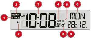
Screen display
- SINCE icon (Total rainfall)
- HISTORY icon (History data)
- Time
- Daylight saving time (DST) on
- Ice pre-alert on
- Weekday
- Alarm Mode
- Alarm on
- Day and Month
- Rainfall indicator
- Past time
- Histogram
- Time range record indicator
- Current Rainfall reading
- HI Alert
- HI Alert on
- Rainfall unit (in/h, mm/h)
- Outdoor indicator
- MAX/MIN indicator
- Outdoor temperature
- Battery level indicator (sensor)
- Outdoor sensor signal strength indicator
- HI/LO Alert and Alarm on
- Indoor indicator
- Indoor humidity
- MAX/MIN indicator
- Indoor temperature
- Battery level indicator (base station)
- HI/LO Alert for humidity and Alarm on
- HI/LO Alert for temperature and Alarm on
Before starting operation
NOTICE
![]() Avoid connection faults!
Avoid connection faults!
In order to avoid connection problems between the devices, the following points must be observed during commissioning.
- Place the base unit (receiver) and sensor (transmitter) as close together as possible.
- Connect the power supply to the base unit and wait until the indoor temperature is displayed.
- Establish power supply for the sensor.
- Set up/operate the base unit and sensor within the effective transmission range.
- Make sure that the base unit and the radio sensor are set to the same channel.
When changing the batteries, always remove the batteries in both the base unit and the sensor and reinsert them in the correct order so that the radio connection can be re-established. If one of the two devices is operated via a mains power connection, the power connection for this device must also be disconnected briefly when changing the battery. If, for example, only the batteries in the sensor are replaced, the signal cannot be received or can no longer be received correctly.
Note that the actual range depends on the building materials used in the building and the position of the base unit and outdoor sensor. External influences (various radio transmitters and other sources of interference) can greatly reduce the possible range. In such cases, we recommend finding other locations for both the base unit and the outdoor sensor. Sometimes a shift of just a few centimetres is enough!
Setting up power supply
Basestation
- Remove the battery compartment cover.
- Insert the batteries into the battery compartment. Ensure that the battery polarity (+/-) is correct.
- Replace the battery compartment cover.
- Wait until the indoor temperature is displayed on the base station.
Remote sensor
- Loosen the screws at the battery compartment cover with a small Philips screwdriver and remove the cover.
- Insert the batteries into the battery compartment. Ensure that the battery polarity (+/-) is correct.
- Replace the cover and retighten it with the screw.
Battery replacement
- Press the RESET button on the sensor after every battery change.
- Press the SCAN button on the base station to re-establish pairing.
Attaching rubber linings
Attach the supplied self-adhesive rubber pads to the clamps as shown to ensure a firmer fitting of the mounting rod.
Remote sensor installation and mounting
Depending on the desired location, the remote sensor can be put on the table or mounted on the wall.
NOTICE! During the installation make sure that the device is minimum 1.5 meters off the ground.
The location should be as free as possible from obstacles to ensure an accurate measurement. The remote sensor should be installed / mounted horizontally and within 100 m of the base unit.
Installation on a vertical tube (maximal tube diameter: 26 mm)
- Place the back of the mounting base of the remote sensor on the tube and press the mounting clamp against the tube from the other side.
- Slide 4 screws through the bore holes of the mounting clamp and through the bore holes of the mounting base on the other site.
- Put on the 4 nuts and tighten the screw connection by hand.
Automatic time setting
After the power supply was established, the clock will automatically search for the radio signal. It takes about 3-8 minutes to complete this process.
If the radio signal is received correctly, the date and time will be set automatically and the radio control signal icon turns on.
If the clock fails to receive the time signal, go ahead with the following steps:
- Press RCC button on the base station until radio signal symbol flashes.
- If the device is still not receiving the signal, the time must be set manually.
Manual time setting
To set the time / date manually, first disable the reception of the time signal by pressing the RCC button for approx. 8 seconds.
- Press and hold CLOCK button for approx. 3 seconds to change to time setting mode.
- Digits to be set are flashing.
- Press UP or DOWN button to change the value.
- Press CLOCK button to confirm and continue to the next setting.
- Settings order: 12/24-hours mode > Hours > Minutes > Year > Month and Day > Day and Month > Time offset > Language > Daylight Saving Time (DST)
- Finally press the CLOCK button to save the settings and exit the setting mode.
Wake-up call setting
Setting the alarm time
- Press the ALARM button for approx. 2 seconds to enter the alarm time settings mode.
- Digits to be set are flashing.
- Press UP or DOWN button to change the value.
- Press the ALARM button to confirm the entry and move to the next setting.
- Settings sequence: Hours > minutes
- Finally, press the ALARM button to save the settings and exit the settings mode.
Switching the alarm clock (and frost warning) on/off
- Press the ALARM button to display the alarm time.
- Press the ALARM button again to enable the alarm. The symbol will displayed on the LCD.
- Press the ALARM button once more to activate the frost warning alarm time. The symbols and are shown on the display.
- To deactivate the alarm and frost warning, press the ALARM button until the alarm icons are no longer displayed.
Snooze function
- When the alarm sounds, press the SNZ/LIGHT button to activate the snooze function. Wake-up call sounds again after 5 minutes.
- When the alarm sounds, press any other key to stop the alarm until the set alarm time is reached again.
- If no key is pressed, the alarm is automatically switched off after 2 minutes.
Receiving measurements automatically
Once batteries are installed, the base station will display the measurement readings. Readings from the remote sensor will be displayed within 3 minutes after powering it on.
Rainfall
The base station displays how many millimeters / inches of rainfall are accumulated over a time period, based on the current rainfall rate, that is updated every minute.
Select display mode
Press the RAIN button several times until the desired time range is displayed:RATE: Current rainfall rate in past hourHOUR: Total rainfall rate for current hourDAY: Total rainfall rate within the current day, from midnightWEEK: Total rainfall rate for current weekMONTH: Total rainfall rate for current monthYEAR: Total rainfall rate for within a year (from first day of the year)
The measurement unit (millimeter or inch) for rainfall is selected via the MM / IN sliding switch.
Graphical histogram
- The Histogram presents an easy view of rainfall change pattern over a a period of time in a graphical manner.
- The time scale of the graph automatically changes according to the rainfall display modes. Settings order: Rate> Hour > Day > Week > Month > Year
- By default, the graph is presented in hourly scale.
- There is no graphical display when yearly rainfall is selected.
To Check history data:
- Press RAIN button to select rainfall display modes.
- Settings order: the last 24 hours > the last 31 days > the last 52 weeks > the last 12 months > the last 5 years
Since function for rainfall
- Press the SINCE button to display the total rainfall from a customized point in time.
- To delete the current data: Press and hold the SINCE button until the stored value is cleared. The new value is now equal to day rainfall and the base unit will start again to collect the rainfall data.
Manual measurement display
- Press MEM button several times to display the saved values one after another.
- Display order: Current values > MAX (highest values) > MIN (lowest values)
- When displaying highest or lowest values, press and hold MEM button for approx. 3 seconds to delete all saved values.
HI/LO Alert
HI/LO alert are used to alert you of certain weather conditions. Once activated, the alarm will turn on and the indicator light starts flashing when a certain criterion is met. The following are areas and type of alert provided:
| Area | Type of alert available |
| Indoor temperature | HI AL / LO AL |
| Humidity (indoor) | HI AL / LO AL |
| Outdoor temperature | HI AL / LO AL |
| Rainfall (hourly) | HI AL |
| Rainfall (daily) | HI AL* |
HI AL = High alert / LO AL = Low alert*Daily rainfall since midnight
HI/LO alert setting
- Press ALERT button until the desired area is selected.
- Press UP or DOWN button to change the value.
- Press ALERT button to confirm and continue to the next setting.
Enable/Disable HI/LO Alert
- Press ALERT button until the desired area is selected.
- Press ALARM button, to activate the alarm.
- Press ALERT button to confirm and continue to the next setting.
Note:
- The unit will automatically exit setting mode in 5 seconds if no button is pressed.
- When ALERT alarm is on, the area and type of alarm that triggered the alarm will be flashing and the alarm will sound for 2 minutes.
- Press SNOOZE/LIGHT button when alarm sounds to interrupt the alarm. The alarm will then start again after 2 minutes
Data clearing
- Press and hold HISTORY button for approx. 3 seconds.
- Press UP or DOWN button to choose YES or NO.
- Press HISTORY button to confirm. This will clear out any rainfall data recorded before.
Technical data
|
Main unit |
|
| Batteries | 2x AA, 1.5 V |
| Temperature unit | °C / °F |
| Temperature measuring range | -10°C – 50°C |
| Humidity measuring range | 20% – 90% |
| Time display | HH:MM:SS / Weekday |
| Time format | 12 or 24 hours |
| Calendar display | DD/MM/YR or MM/DD/YR |
| Dimensions | 95 x 155 x 23 mm (W x H x D) |
| Weight | 212 g (without batteries) |
|
Wireless Rain gauge sensor |
|
| Batteries | 4x AA, 1.5 V |
| Transmission frequency | 868 MHz |
| Maximum radio-frequency power | < 25mW |
| Temperature unit | °C / °F |
| Temperature measuring range | -40°C – 60°C |
| Rainfall unit | mm, inch |
| Rainfall measuring range | 0 – 29999 mm |
EC declaration of conformity
Hereby Bresser GmbH declares that the radio equipment type with 7002530 complies with Directive 2014/53/EU. The full text of the EC declaration of conformity is available at the following Internet address www.bresser.de/download/7002530/CE/7002530_CE.pdf
UKCA Declaration of Conformity
 Bresser GmbH has issued a “Declaration of Conformity” in accordance with applicable guidelines and corresponding standards. The full text of the UKCA declaration of conformity is available at the following internet address: www.bresser.de/download/7002530/UKCA/7002530_UKCA.pdf
Bresser UK Ltd.
Suite 3G, Eden House, Enterprise Way, Edenbridge, Kent TN8 6Hf, Great Britain
Disposal
![]() Dispose of the packaging materials properly, according to their type, such as paper or cardboard. Contact your local waste-disposal service or environmental authority for information on the proper disposal.
Dispose of the packaging materials properly, according to their type, such as paper or cardboard. Contact your local waste-disposal service or environmental authority for information on the proper disposal.
![]() Do not dispose of electronic devices in the household garbage!
Do not dispose of electronic devices in the household garbage!
According to the European Directive 2012/19/EU on Waste Electrical and Electronic Equipment and its transposition into national law, used electrical equipment must be collected separately and recycled in an environmentally sound manner.
Batteries and rechargeable batteries must not be disposed of with household waste. You are legally obliged to return used batteries and accumulators and can return the batteries after use either in our sales outlet or in the immediate vicinity (e.g. in the trade or in municipal collection points) free of charge.
Batteries and accumulators are marked with a crossed-out dustbin and the chemical symbol of the pollutant, “Cd” stands for cadmium, “Hg” stands for mercury and “Pb” stands for lead.
Service
Please contact the service centre first for any questions regarding the product or claims, preferably by e-mail.e-mail: [email protected]Telephone: +44 1342 837 098BRESSER UK LtdCustomer SupportSuite G3, Eden HouseEnterprise WayEdenbridge, Kent TN8 6HFUnited Kingdom
ContactBresser GmbHGutenbergstraße 246414 Rhede · Germanywww.bresser.de
![]() @BresserEurope
@BresserEurope
 report this ad
References
[xyz-ips snippet=”download-snippet”]