BRESSER ClimaTemp FSX Weather Station Instruction Manual
Imprint
Bresser GmbHGutenbergstr. 246414 RhedeGermanywww.bresser.de
For any warranty claims or service enquiries, please refer to the information on “Warranty” and “Service” in this documentation. We apologize for any inconvenience caused by the fact that we cannot process enquiries or submissions sent directly to the manufacturer’s address.Errors and technical changes excepted.© 2021 Bresser GmbH All rights reserved.The reproduction of this documentation – even in extracts – in any form (e.g. photocopy, print, etc.) as well as the use and distribution by means of electronic systems (e.g. image file, website, etc.) without the prior written permission of the manufacturer is prohibited.The designations and brand names of the respective companies used in this documentation are generally protected by trade, trademark and/or patent law in Germany, the European Union and/or other countries.
Validity note
This documentation is valid for the products with the following article numbers: 7060200Manual version: 0521Manual designation: Manual_7060200_ClimaTemp-FSX_en-de-fr-esnl_BRESSER_v052021aAlways provide information when requesting service.
About this Instruction Manual
 NOTICEThese operating instructions are to be considered a component of the device.Read the safety instructions and the operating manual carefully before using this device.Keep this instruction manual in a safe place for future reference. When the device is sold or given to someone else, the instruction manual must be provided to the new owner/ user of the product.
Parts overview and scope of delivery
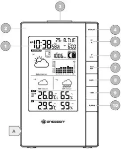
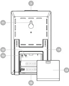

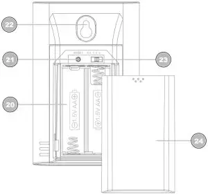
Illustration 1: Parts overview for base station (top) and remote sensor (bottom)
- Display
- Housing
- SNOOZE/LIGHT button (snooze function and temporary background lighting)
- HISTORY button (retrieve measurements for the past 24 hours)
- CH/UP button (sensor channel selection or value change upwards)
- 12/24/DOWN button (time mode selection or value change downwards)7 MAX/MIN button (switch between highest, lowest or current value display)
- BARO button (display of different atmospheric pressure values)
- TIME button (manual time setting)
- ALARM button (Alarm setting)
- Wall mount fixture 12 °C/°F button (temperature format setting)
- RESET button (reset all settings)
- Stand, fold-out
- Battery compartment cover 16 Battery compartment
- Display 18 Function indicator (data transmission)
- Housing 20 Battery compartment
- RESET button (reset all settings)
- Wall mount fixture
- Channel switch 24 Battery compartment cover
Scope of deliveryBase station (A), remote sensor (B)Also required (not included): 4 pcs. Mignon batteries (1.5V, AA type)
Screen display

Illustration 2: Display of the base unit
- AM/PM information in 12-hour time mode
- Current time (hours:minutes:seconds)
- Alarm symbol (alarm 1 or 2 enabled)
- Symbol for active daylight saving time (DST)
- Date (month-day or reverse)
- Weekday
- Transmission symbol (radio-controlled clock CET)
- Alarm (AL1 or AL2)
- Air pressure (mb/hPa or inHg)
- Moon phase
- Bar chart for air pressure history
- Weather trend (72 hours)
- Humidity outdoors
- Humidity indoors
- Battery status
- Temperature (indoor)
- Temperature (outdoor)
- Channel info (sensors)
- Sensor signal status
- Weather trend (48 hours)
- Weather trend (24 hours)
- Singles values for air pressure history (up to 24 hours)
Before commissioning
![]() NOTICEAvoid connection faults!In order to avoid connection problems between the devices, the following points must be observed during commissioning.
NOTICEAvoid connection faults!In order to avoid connection problems between the devices, the following points must be observed during commissioning.
- Place the base unit (receiver) and sensor (transmitter) as close together as possible.
- Connect the power supply to the base unit and wait until the indoor temperature is displayed.
- Establish power supply for the sensor.
- Set up/operate the base unit and sensor within the effective transmission range.
- Make sure that the base unit and the radio sensor are set to the same channel.
When changing the batteries, always remove the batteries in both the base unit and the sensor and reinsert them in the correct order so that the radio connection can be re-established. If one of the two devices is operated via a mains power connection, the power connection for this device must also be disconnected briefly when changing the battery. If, for example, only the batteries in the sensor are replaced, the signal cannot be received or can no longer be received correctly.Note that the actual range depends on the building materials used in the building and the position of the base unit and outdoor sensor. External influences (various radio transmitters and other sources of interference) can greatly reduce the possible range. In such cases, we recommend finding other locations for both the base unit and the outdoor sensor. Sometimes a shift of just a few centimetres is enough!Though the remote unit is weather proof, it should be placed away from direct sunlight, rain or snow.
Setting up power supply
Base unit
- Remove the battery compartment cover.
- Insert the batteries into the battery compartment. Ensure that the battery polarity (+/-) is correct.
- Replace the battery compartment cover.
- Wait until the indoor temperature is displayed on the base station.Remote sensor
- Remove the battery compartment cover.
- Insert the batteries into the battery compartment. Ensure that the battery polarity (+/-) is correct.
- Move the CH slide control to the position for the desired transmission channel (setting CH1, CH2 or CH3 with screen display).
- Replace the battery compartment cover.
NOTICE! When operating one outdoor sensor, channel 1 is recommended as the default setting.
Battery level indicator
- When the level of the batteries in the base station or in the wireless sensor reaches a critical level, the battery level symbol appears in the appropriate area on the display.
- When replacing one set of batteries, always remove the batteries from the other part of the unit and reinsert them in the correct order (see chapter “Setting up power supply”). Replace the batteries to be changed in the corresponding part of the device with a completely new set with full capacity. This ensures that the connection between the devices will be reestablished again correctly.
Automatic time setting
After the power supply was established, the clock will automatically search for the radio signal. This will take approximately 3 to 8 minutes to finish this process.
If the radio signal is received correctly, the date and time will be set automatically and the radio control signal icon turns on.If the clock fails to receive the time signal, go ahead with the following steps:
- Press °C/°F button on the base station for approx. 3 seconds to initate RC signal reception again.
- If the device is still not receiving the signal, the time must be set manually.
Manual time setting and other user defined settings
- Press the SNOOZE/LIGHT button for about 8 seconds to deactivate the automatic time setting. The reception symbol for the radio-controlled watch disappears from the display.
- In normal display mode, press the TIME SET button for about 2 seconds to enter the settings mode.
- Digits to be set are flashing.
- Press CH/UP or 12/24/DOWN button to change the value.
- Press the TIME button to confirm and switch to the next setting.
- Sequence of the settings: Year > Change day/month display > Month > Day > Daylight saving time (DST) AUTO/OFF (off) > Hours > Minutes > Seconds > Language > Time zone (-23 to +23 hours)
- Finally press the MODE/SET button to save the settings and exit the settings mode.
- NOTICE! To restore the automatic time setting, press the SNOOZE/LIGHT button again for 8 seconds. The reception symbol for the radio-controlled watch reappears in the display.
Alarm settings
- In normal display mode, press the TIME button several times to display the Alarm time AL1 or AL2.
- Press ALARM button for approx. 3 seconds to enter the alarm time setting mode.
- Digits to be set are flashing.
- Press CH/UP or 12/24/DOWN button to change the value.
- Press ALARM button to confirm and continue to the next setting.
- Settings order: hours > minutes > ice alert on/offNOTICE! If ice alert is enabled (on), the alarm will sound 30 seconds before the set alarm time if the temperature is -3° or below.
- Finally press the ALARM button to save the settings and exit the setting mode. Alarm will be activated automatically. The
 symbol will be displayed.
 - In normal display mode, press the ALARM button several times to enable alarm time AL1, AL2 or both. If the alarm is enabled, the corresponding symbol will be displayed ( 1, 2 or 12).
Snooze function
- When the alarm sounds press the SNOOZE/LIGHT button to activate the snooze function. The alarm will sound again in 5 minutes.
- Press ALARM button when the alarm sounds to interrupt the alarm until the alarm time will be reached again.
- The alarm will be turned off automatically if no button is pressed within 2 minutes.
Receiving measurements automatically
Once the power supply is enabled, the base station will display the measurement readings for indoors. Readings from the outdoor sensor will be displayed within 3 minutes after powering it on.If no signal is received, proceed as follows:Press 12/24 button for approx. 3 seconds to initate reception of measurements again.
Moon phases
This weather station is able to display the moon phases for the northern hemisphere. Here the moon grows from the right. This is because the sunlit side of the moon in the northern hemisphere moves from right to left. The following table shows the representations of the moon phases.


Illustration 3: Moon phases for the northern hemispere.
- New moon
- Waxing crescent
- First quarter
- Waxing gibbous
- Full moon
- Waning gibbous
- Third quarter
- Waning crescent
Weather Trend
The weather station will calculate a weather trend for the next 12 hours on basis of the measured values.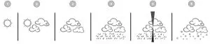
Illustration 4: Weather trend indicators
- Sunny
- Partly cloudy
- Cloudy
- Rain
- Storm
- Snow
Trend arrow indicators
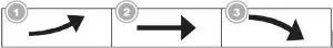
- Rising
- Steady
- Falling
The temperature and humidity trend indicator shows the trends of changes in the forthcoming few minutes. Arrows indicate a rising, steady or falling trend.
Barometric / Atmospheric Pressure
Atmospheric Pressure is the pressure at any location on earth, caused by the weight of the column of air above it.One atmospheric pressure refers to the average pressure 17 / 108 and gradually decreases as altitude increases. Meteorologists use barometers to measure atmospheric pressure.Since variation in atmospheric pressure is greatly affected by weather, it is possible to forecast the weather by measuring the changes in pressure.
- Press the BARO button to switch between barometric pressure display in inHg or in hPa.
- Press the BARO button for 3 seconds to change between absolute and relative atmospheric pressure.
- ABSOLUTE: the absolute atmospheric pressure of your location.
- RELATIVE: the relative atmospheric pressure based on the sea level.Set relative atmospheric pressure value
- Get the atmospheric pressure data of the sea level (it is also the relative atmospheric pressure data of your home area) through the local weather service, internet and other channels.
- Press and hold the BARO button for approx. 3 seconds until “abs” or “rel” flashes.
- Press CH/UP or 12/24/DOWN button to switch to “rel” mode.
- Press the BARO button and the number for “rel” flashes.
- Press CH/UP or 12/24/DOWN button to change the value.
- Press the BARO button to save and exit the setting mode.NOTE
- The default relative atmospheric pressure value is 1013 mb/hPa (29.91 inHg), which refers to the average atmospheric pressure.
- When you change the relative atmospheric pressure value, the weather indicators will change along with it.
- The built-in barometer can notice the environmental absolute atmospheric pressure changes. Based on the collected data a forecast for the weather conditions in the next 12 hours can be made. Therefore, the weather indicators will change according to the detected absolute atmospheric pressure after you operate the clock for 1 hour.
- The relative atmospheric pressure is based on the sea level, but it will change with the absolute atmospheric pressure changes after operating the clock for 1 hour.
Connecting remote sensors
The Weather Station can display the readings from up to 3 wireless sensors* of the same type. Each radio sensor must be set to a separate channel. Proceed as follows to set the channel:
- Remove the battery compartment cover of the wireless sensor.
- Set the channel selection switch to the desired channel (CH1, CH2 or CH3).
- Re-attach the battery compartment cover.
- NOTICE! Each connected wireless sensor must be set to a different channel. If only one wireless sensor is connected, it should be set to CH1.
- Press the CH/UP button on the base station several times to display the measured values for the individual channels. The selected channel is shown in the display.
- one wireless sensor included, others optionally available
Temperature display
Press the °C/°F button to switch between the temperature display in °C or °F.When temperatures of -40°C or below and humidity of 20% or below are reached, the information “LO” is output for the respective range.At temperatures of 70°C or higher and a humidity of 90% or higher, the information “HI” is displayed.For values outside the measurable range “- -” is displayed.When returning to a measurable temperature range, the corresponding temperature is displayed again.
History record for the past 24 hours
The base station automatically records air pressure readings from the last 24 hours.If necessary, press the HISTORY button several times to display the history data for the hourly values (HOUR – up to 24 hours backwards) for the pressure one after the other.When a history date is displayed, press any key (except HISTORY) to return to the normal display mode.
NOTICE! In the history bar graph the values for the pressure of the last 24 hours can be read at any time in compressed form.
MAX/MIN Weather data
The main unit saves highest and lowest value records for indoor and outdoor temperature as well as for humidity for 24 hours:
- Press the MAX/MIN button repeatedly to display the stored values of the base station and the currently set remote sensor one after another.
- Display order: Highest values > Lowest values > Current values
- Press MAX/MIN button for approx. 3 seconds to delete all values of the current recording period.
- NOTICE! When the batteries are changed, all values of the current recording period will also be deleted.
Technical data
Base stationBatteries: 2x AA, 1.5 VRadio controlled signal: DCFMaximum number of sensors: 3Temperature unit: °C/°FHumidity measuring range: 20% to 90%Humidity resolution: 1%Temperature measuring range: -5°C to 50°C (23°F to 122°F)Barometric pressure unit: 540 hPa to 1100 hPa / 15.95 to 32.49 inHgTime format: 12 or 24 hoursDimensions: (WxHxD) 100 x 161 x 21.5 mm
Remote sensorBatteries :2x AA, 1.5 VTransmission frequency: 433 MHzTransmission measuring range: 30 mTemperature unit: °CTemperature measuring range: -20°C to 60°C (-4°F to 140°F)Humidity measuring range: 1% to 90%Humidity resolution: 1%Dimensions (W x H x D): 65 x 100 x 35 mm
 EC declaration of conformityA “Declaration of conformity” in accordance with the applicable directives and corresponding standards has been prepared by Bresser GmbH. The full text of the EC declaration of conformity is available at the following Internet address: www.bresser.de/download/7060200/CE/7060200_CE.pdf
Visit our website via the following QR Code or web link to find further information on this product or the available translations of these instructions.
 http://www.bresser.de/P7060200
WARRANTY
 report this ad

References
[xyz-ips snippet=”download-snippet”]